EP0551486B1 - Store a lamelles a commande unique - Google Patents
Store a lamelles a commande unique Download PDFInfo
- Publication number
- EP0551486B1 EP0551486B1 EP92916771A EP92916771A EP0551486B1 EP 0551486 B1 EP0551486 B1 EP 0551486B1 EP 92916771 A EP92916771 A EP 92916771A EP 92916771 A EP92916771 A EP 92916771A EP 0551486 B1 EP0551486 B1 EP 0551486B1
- Authority
- EP
- European Patent Office
- Prior art keywords
- rod
- blind
- lift
- tilting member
- tilter
- Prior art date
- Legal status (The legal status is an assumption and is not a legal conclusion. Google has not performed a legal analysis and makes no representation as to the accuracy of the status listed.)
- Expired - Lifetime
Links
Images


Classifications
-
- E—FIXED CONSTRUCTIONS
- E06—DOORS, WINDOWS, SHUTTERS, OR ROLLER BLINDS IN GENERAL; LADDERS
- E06B—FIXED OR MOVABLE CLOSURES FOR OPENINGS IN BUILDINGS, VEHICLES, FENCES OR LIKE ENCLOSURES IN GENERAL, e.g. DOORS, WINDOWS, BLINDS, GATES
- E06B9/00—Screening or protective devices for wall or similar openings, with or without operating or securing mechanisms; Closures of similar construction
- E06B9/24—Screens or other constructions affording protection against light, especially against sunshine; Similar screens for privacy or appearance; Slat blinds
- E06B9/26—Lamellar or like blinds, e.g. venetian blinds
- E06B9/28—Lamellar or like blinds, e.g. venetian blinds with horizontal lamellae, e.g. non-liftable
- E06B9/30—Lamellar or like blinds, e.g. venetian blinds with horizontal lamellae, e.g. non-liftable liftable
- E06B9/303—Lamellar or like blinds, e.g. venetian blinds with horizontal lamellae, e.g. non-liftable liftable with ladder-tape
- E06B9/307—Details of tilting bars and their operation
-
- E—FIXED CONSTRUCTIONS
- E06—DOORS, WINDOWS, SHUTTERS, OR ROLLER BLINDS IN GENERAL; LADDERS
- E06B—FIXED OR MOVABLE CLOSURES FOR OPENINGS IN BUILDINGS, VEHICLES, FENCES OR LIKE ENCLOSURES IN GENERAL, e.g. DOORS, WINDOWS, BLINDS, GATES
- E06B9/00—Screening or protective devices for wall or similar openings, with or without operating or securing mechanisms; Closures of similar construction
- E06B9/24—Screens or other constructions affording protection against light, especially against sunshine; Similar screens for privacy or appearance; Slat blinds
- E06B9/26—Lamellar or like blinds, e.g. venetian blinds
- E06B9/28—Lamellar or like blinds, e.g. venetian blinds with horizontal lamellae, e.g. non-liftable
- E06B9/30—Lamellar or like blinds, e.g. venetian blinds with horizontal lamellae, e.g. non-liftable liftable
- E06B9/303—Lamellar or like blinds, e.g. venetian blinds with horizontal lamellae, e.g. non-liftable liftable with ladder-tape
- E06B9/308—Lamellar or like blinds, e.g. venetian blinds with horizontal lamellae, e.g. non-liftable liftable with ladder-tape with coaxial tilting bar and raising shaft
-
- E—FIXED CONSTRUCTIONS
- E06—DOORS, WINDOWS, SHUTTERS, OR ROLLER BLINDS IN GENERAL; LADDERS
- E06B—FIXED OR MOVABLE CLOSURES FOR OPENINGS IN BUILDINGS, VEHICLES, FENCES OR LIKE ENCLOSURES IN GENERAL, e.g. DOORS, WINDOWS, BLINDS, GATES
- E06B9/00—Screening or protective devices for wall or similar openings, with or without operating or securing mechanisms; Closures of similar construction
- E06B9/24—Screens or other constructions affording protection against light, especially against sunshine; Similar screens for privacy or appearance; Slat blinds
- E06B9/26—Lamellar or like blinds, e.g. venetian blinds
- E06B9/28—Lamellar or like blinds, e.g. venetian blinds with horizontal lamellae, e.g. non-liftable
- E06B9/30—Lamellar or like blinds, e.g. venetian blinds with horizontal lamellae, e.g. non-liftable liftable
- E06B9/32—Operating, guiding, or securing devices therefor
- E06B9/322—Details of operating devices, e.g. pulleys, brakes, spring drums, drives
-
- E—FIXED CONSTRUCTIONS
- E06—DOORS, WINDOWS, SHUTTERS, OR ROLLER BLINDS IN GENERAL; LADDERS
- E06B—FIXED OR MOVABLE CLOSURES FOR OPENINGS IN BUILDINGS, VEHICLES, FENCES OR LIKE ENCLOSURES IN GENERAL, e.g. DOORS, WINDOWS, BLINDS, GATES
- E06B9/00—Screening or protective devices for wall or similar openings, with or without operating or securing mechanisms; Closures of similar construction
- E06B9/24—Screens or other constructions affording protection against light, especially against sunshine; Similar screens for privacy or appearance; Slat blinds
- E06B9/26—Lamellar or like blinds, e.g. venetian blinds
- E06B9/28—Lamellar or like blinds, e.g. venetian blinds with horizontal lamellae, e.g. non-liftable
- E06B2009/285—Means for actuating a rod (being tilt rod or lift rod)
-
- E—FIXED CONSTRUCTIONS
- E06—DOORS, WINDOWS, SHUTTERS, OR ROLLER BLINDS IN GENERAL; LADDERS
- E06B—FIXED OR MOVABLE CLOSURES FOR OPENINGS IN BUILDINGS, VEHICLES, FENCES OR LIKE ENCLOSURES IN GENERAL, e.g. DOORS, WINDOWS, BLINDS, GATES
- E06B9/00—Screening or protective devices for wall or similar openings, with or without operating or securing mechanisms; Closures of similar construction
- E06B9/24—Screens or other constructions affording protection against light, especially against sunshine; Similar screens for privacy or appearance; Slat blinds
- E06B9/26—Lamellar or like blinds, e.g. venetian blinds
- E06B9/28—Lamellar or like blinds, e.g. venetian blinds with horizontal lamellae, e.g. non-liftable
- E06B9/30—Lamellar or like blinds, e.g. venetian blinds with horizontal lamellae, e.g. non-liftable liftable
- E06B9/32—Operating, guiding, or securing devices therefor
- E06B9/322—Details of operating devices, e.g. pulleys, brakes, spring drums, drives
- E06B2009/3225—Arrangements to aid the winding of cords rollers
Definitions
- Our invention relates to venetian blinds, and, more particularly to monocontrol venetian blinds that use the same operating control both for controlling the tilting of the slats, and for raising and lowering the blind.
- the headrail mechanism of a venetian blind must provide for two operations; first, lifting and lowering the blind, and second, controllably tilting the slats to open or close the blind or set the slats at any desired angle.
- the ideal monocontrol headrail mechanism would require low operating effort, even when lifting heavy and long blinds. It would provide for accumulating the lift cords or tapes within a relatively small headrail. It would have a tilt mechanism capable of providing good closure. And finally, it would contain a minimum of parts and be easy to assemble and require a minimum of adjustment.
- the prior art does contain a number of designs for monocontrol Venetian blinds. Some of them do not tilt sufficiently to provide good closure. Many of them use a large number of complex parts and are difficult to adjust.
- the prior art reveals two general methods for accumulating lift cords or tapes within a Venetian blind headrail.
- One method is to wind the lift cords or tapes onto spools.
- This method suffers the two disadvantages.
- One disadvantage is that the cords or tapes do not wind evenly onto their respective spools, and very slight differences in diameter produce easily noticeable unevenness in the blind as it is raised.
- the other disadvantage is that the mechanical advantage of the lift mechanism decreases as the diameter of the accumulated cord or tape increases on the spools. This progressive decrease in mechanical advantage occurs as the lift cords support more of the blind's weight, causing a large increase in the effort required to further lift the blind. The mechanical advantage decreases just when it should increase.
- the other, and preferred method is to accumulate the cords onto a shaft that moves laterally, or traverses, so that the lift cords wind in a single layer onto the shaft. This insures even winding of each of the lift cords, and it maintains a constant mechanical advantage so that the lifting effort increases only in proportion to the weight supported by the lift cords.
- Several methods have been used to produce the traversing of the rod. A rack and gear arrangement has been used.
- U.S. Patent No. 1,343,527 reveals a lead screw and nut to accomplish the traversing. Another method, one that is free of any gears or leadscrews, is revealed in U.S. Patent No.
- the headrail mechanism must also provide for tilting the slats of a Venetian blind.
- a monocontrol blind that employs a traversing rod on which to accumulate the lift cords
- the tilt mechanism In a monocontrol blind that employs a traversing rod on which to accumulate the lift cords, the tilt mechanism must rotate in either direction along with the traversing rod until the position for full closure is reached. Thereafter, the tilt mechanism must slip, maintaining its position, while the blind is raised or lowered.
- the drive shaft for the tilt mechanism is the traversing rod.
- the ladder cords are attached to the tilter mechanism.
- a line between these attachment points should pass through the centerline of the traversing rod. This will keep the tilter at the same angle as the slats. If this geometric relationship is not maintained, then it will be necessary for the tilt mechanism to be capable of lifting the blind if full closure is to be achieved.
- the leading end of the tilter contacts a stop which prevents further movement of the tilter and partially releases the grip of the tilter on the rod, thereby limiting the frictional drag of the tilters on the rod to just that amount of torque required to maintain the fully tilted condition of the blind.
- the rod can continue to rotate, winding or unwinding the lift cords to raise or lower the blind according to the direction in which the rod is being rotated.
- EP-A1-0 380 346 discloses a slat raising lowering and rotating apparatus for a horizontal type venetian blind.
- a rod moves axially as it rotates.
- a tilting member consists of a spring and a support for a ladder cord. The spring makes frictional contact with the rod. When the spring is rotated by the rod, at some point it contacts a stop, which resists further rotation and tends to loosen the spring, loosening its grip on the rod so as to reduce its frictional resistance to further rotation of the rod.
- the tilting member As the tilting member is supported by the rod, the tilting member imposes high amounts of frictional drag on the rod, such that it does not traverse reliably and that high operating effort is required, in particular if the blind nears full extension.
- This tilt and lifting system forms the basis for the introductory part of claim 1.
- the desirable characteristics of the helical band tilter of U.S. Patent No. 4,696,630 can be combined with the traversing rod system according to U.S. Patent No. 4,623,012 to produce a Venetian blind that has monocontrol operation and accumulates the lift cords within the headrail.
- This combination has been tried and found to be unsatisfactory because the tilters impose so much frictional drag on the traversing rod that it does not traverse reliably.
- Our invention consists in providing a novel bearing arrangement that removes much of this frictional drag.
- the band clutch of U.S. Patent No. 4,697,630 is modified so that the tilter is supported directly by the cradle rather than by the traversing rod.
- the blind has good closure, and yet it is easy to raise and lower. It has a small number of parts and is easy to assemble and adjust.
- the inventive combination has the advantages of both the tilting mechanism and the lifting mechanism without the problem of sliding the rod against large frictional forces found in prior art blinds.
- Lift cord carrier 15 is "arranged in a slightly clamping manner" on operating shaft 2. But experience has shown that the tilter must grip the operating shaft tightly during tilting to provide good closure of the blind, and the friction from this tight grip will require the exertion of large forces by the traversing mechanism to cause the shaft to slide.
- the ladder cords support the entire weight. As the blind is raised, weight is transferred to the lift cords. When the blind is fully raised, virtually the entire weight of the slat pack and the bottom rail are supported by the lift cords.
- the ladder cords are attached to the tilters, so whatever supports the tilters must also support the weight of the extended portion of the blind. The normal forces between the tilters and their supports, and the resulting friction caused thereby, can make traversing difficult when the blind nears full extension. At that time the tilters are supporting most of the weight, producing maximum friction, and the tension in the lift cords, which is needed to produce the traversing motion, is at its minimum value.
- F2 corresponds to the force causing the rod to rotate, which forces it to slip within the tilter
- F1 corresponds to the force required to cause the rod to traverse.
- a rod of 0.375" diameter, and lift cords of about 0.040" diameter Since the rod rotates one complete revolution while traversing only a distance equal to the thickness of the cord, the surface motion in the rotational direction is about 30 times the motion in the traversing direction, making the angle A quite small, somewhat less than 2 degrees.
- the force, F2 which causes the rotational motion does most of the work against friction, and F1 is only about 3% of what it would have to be to cause the traversing motion in the absence of F2.
- Another object of our invention is to provide a monocontrol lift and tilt mechanism for Venetian blinds which can exert enough torque to ensure good closure.
- a further object of our invention is to provide a monocontrol lift and tilt mechanism for Venetian blinds which permits the close alignment of the ladder cords at the positions of full tilt.
- Still another object of our invention is to provide a monocontrol lift and tilt mechanism for Venetian blinds in which the entire torque required for tilting does not have to be reacted during raising of the blind.
- Yet a further object of our invention is to provide a monocontrol lift and tilt mechanism for Venetian blinds having a minimum of component parts and which can be easily assembled and adjusted for proper operation.
- Headrail 1 can be of any convenient cross-sectional shape having sufficient interior space to accommodate the hardware.
- Holding mechanism 3 which could be any of a wide variety of devices, is preferably mounted at an end of headrail 1, although other placements are possible. Some appropriate operating means is needed for operating holding mechanism 3. In this case cord loop 5 is shown, although any of a number of other combinations of holding mechanism and operating means might be used instead.
- Splines 7 are attached to the output of holding mechanism 3.
- Splines 7 together with disk 9 which is attached to traversing rod 11 form an axially slidable torque carrying connection between holding mechanism 3 and traversing rod 11.
- the particular spline and disk arrangement shown here for making the connecting to the holding mechanism is intended only as an example, and other means for accomplishing the connection may be used without deviating from the intent and purpose of our invention.
- the remaining parts within the headrail are associated with the attachment, control, and operation of lift cord 13 and ladder cord 15.
- One such set would, ordinarily, be provided for each set of lift and ladder cords.
- the identification of parts, forces, and descriptions of operation are made for one set of these lift and tilt components, and are intended to apply to the other sets as well.
- a partial set of components may be used in one or more locations. For instance, blinds often have three ladder cords but only two lift cords. This is done when two lift cords are sufficient to lift the blind, but a central ladder cord is still needed for proper support of the slats. In such cases, the operation of the blind remains the same as it relates to the components in the incomplete set.
- Cradle 17 and tilter 19 are arranged generally in accordance with the principles of U.S. Patent No. 4,697,630.
- Each of the side of ladder cord 15 is attached to one of the two arms 21 of tilter 19 as best seen in FIG. 4.
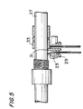
- Lift cord 13 is arranged generally in accordance with the principles of U.S. Patent No. 4,623,012, entering the headrail through a hole in the bottom of the rail, passing over roller 23, seen in FIG. 5, and terminating in its attachment to rod 11 by means of clip 25 or by any other suitable means.
- FIG. 5 shows the prior art combination of a traversing rod lift system according to the principles of U.S. Patent No. 4,623,012 with a helical band tilter according to the principles of U.S. Patent No. 4,697,630.
- Traversing rod 27 is supported directly by cradle 29 whose bearing surface 31 is shaped to accept rod 27.
- Tilter 33 is disposed about and entirely supported by rod 27.
- FIG. 6 shows the tilt and lift components of our invention with the slats in a horizontal position.
- arms 21, shown in FIG. 4, but omitted from FIG. 5 for clarity, would lie in the horizontal plane passing through the center of rod 35.
- Tilter 37 is wrapped about rod 35 as in the earlier embodiment, but in this case the tilter has bearing 39 which is supported at bearing surface 41 on cradle 43.
- Flange 45 at the end of tilter 37 forms a retaining barrier to prevent axial movement of tilter 37 in relation to cradle 43 along rod 35.
- the outer surface of flange 45 is angled to form camming surface 47 according to the principles of U.S. Patent No. 4,623,012. The angle is shown in FIG. 6 as angle A.
- angle A depends upon the ratio of the diameter of lift cord 49 to the diameter of the rod. Sufficient movement must be produced by the camming action to provide space for the incoming cord so that it will not override the previous turns.
- very little of the blind's weight is supported at the surface between rod 35 and tilter 37. Instead, most of the weight is supported at bearing surface 41 between cradle 35 and tilter 37. This reduction of frictional force between the tilter and the traversing rod allows the rod to be moved much more easily. With this improved bearing support for tilter 37, much less tension in lift cord 49 is needed to insure the complete return of traversing rod 35 to its starting position as the blind is fully lowered.
- FIG. 7 shows the same components as shown in FIG. 6 but during lifting of the blind.
- Lift cord 49 as it is wound onto rod 35, contacts camming surface 47, forcing rod 35 to traverse to the left, away from the camming surface.
- Tilter 37 is fully rotated to the limit permitted by stop 51 which loosens the grip of tilter 37 on rod 35, retaining only sufficient grip to maintain its orientation.
- arms 53 are roughly vertical, and the ladder cords, of which only the near one, ladder cord 55 is visible, are in the fully tilted position.
- U.S. Patent No. 4,632,012 has no tilter.
- the camming surface is formed as a part of the cradle.
- the cord comes into contact with the tilter flange. Therefore it is necessary to incorporate the camming surface onto this flange.
- One of the features of our inventive blind is that it can be raised by rotating the rod in either direction. This requires that the camming surface be on the right side when the blind is being lifted by counterclockwise rotation of the rod, and on the left for the opposite rotation.
- the tilter rotates 90 degrees in the direction of the rod's rotation. This orients camming surface 47 properly for that winding direction of the lift cord.
- camming action takes place in about a one hundred and twenty degree arc between the point where the cord first contacts the shaft and the top of the shaft.
- camming surface 47 occupies the lower portion of flange 45. As the tilter rotates 90 degrees one way or the other, the camming surface rotates into the required orientation.
- tilters are also supported directly by the cradles rather than by the operating rod which, in this case does not traverse, but simply rotates.
- lifting is accomplished by winding the tape or cord onto spools.
- FIG. 8 show the lifting and tilting components for this embodiment that correspond to the components of the preferred embodiment shown in FIGS. 5 and 6.
- Rod 57 has tilter 59 disposed thereabout.
- Tilter 59 has bearing groove 61 which rotates on and is supported by bearing surface 63 of cradle 65.
- Cradle 65 is similar to cradle 37 of the preferred embodiment except that in place of a roller to guide a lift cord, it has a slot 67 to guide cord or tape 69 onto spool 71. Since there is no traversing of the rod in this case, spool 71 is firmly attached to rod 57 so as to rotate with it.
- tilter 59 must rotate with rod 57 until reaching its stop. Thereafter, it must remain in position, maintaining full tilt, while rod 57 continues to rotate within it to raise or lower the blind. The control of friction is important in this case to insure that there be sufficient grip of the tilter on rod 57 to produce full tilt.
Landscapes
- Engineering & Computer Science (AREA)
- Structural Engineering (AREA)
- Architecture (AREA)
- Civil Engineering (AREA)
- Blinds (AREA)
- Operating, Guiding And Securing Of Roll- Type Closing Members (AREA)
- Shutters For Cameras (AREA)
- Circuit Arrangement For Electric Light Sources In General (AREA)
- Shutter-Related Mechanisms (AREA)
- Transition And Organic Metals Composition Catalysts For Addition Polymerization (AREA)
- Peptides Or Proteins (AREA)
- Audible-Bandwidth Dynamoelectric Transducers Other Than Pickups (AREA)
- Fluid-Damping Devices (AREA)
- Lock And Its Accessories (AREA)
- Specific Sealing Or Ventilating Devices For Doors And Windows (AREA)
- Medicines Containing Material From Animals Or Micro-Organisms (AREA)
- Ladders (AREA)
Claims (14)
- Système combiné d'inclinaison et de relèvement à commande unique pour des stores à lamelles, comprenant :• une tige à déplacement transversal (27 ; 35 ; 57) mobile en rotation le long de l'axe de celle-ci, dans deux directions ;• au moins un élément d'inclinaison hélicoïdal à plusieurs spires rotatif serrant ladite tige (27 ; 35 ; 57) et fixé aux cordons formant échelle (55) desdits stores ;• des moyens pour desserrer, au moins partiellement, l'élément d'inclinaison (33 ; 37 ; 59) par rapport à la tige (27 ; 35 ; 57) sur des positions correspondant à l'inclinaison complète pour chaque direction de rotation;• au moins un cordon de relèvement (49) fixé sur ladite tige (35) et réagissant à la rotation de la tige pour s'enrouler autour de ladite tige (35) et se dérouler depuis celle-ci ;• des moyens pour appliquer une force latérale sur ladite tige à déplacement transversal (35) dans une première direction lorsque ledit cordon de relèvement (49) est enroulé autour de ladite tige (35) ; et• des moyens pour supporter ladite tige à déplacement transversal (35) comprenant au moins une glissière (29 ; 43 ; 65) ayant une surface conçue pour recevoir ladite tige et placée pratiquement ou ledit au moins un cordon de relèvement (49) est fixé sur la tige (35), caractérisé en ce que ladite glissière (43) comporte, de plus, une surface supportant ledit élément d'inclinaison (33 ; 37 ; 59) dans le but de réduire la résistance due au frottement sur la tige (27 ; 35 ; 57).
- Système de la revendication 1, dans lequel lesdits moyens pour desserrer comprennent des moyens pour limiter le mouvement de rotation dudit élément d'inclinaison sur lesdites positions d'inclinaison complète.
- Système de la revendication 2, dans lequel lesdits moyens limiteurs comprennent au moins une butée (51) pour desserrer la prise dudit élément d'inclinaison (37) sur ladite tige (35), sur lesdites positions d'inclinaison complète.
- Système de la revendication 2, dans lequel ledit au moins un élément d'inclinaison comprend une partie centrale formée pour serrer la tige, et deux bras (53) pour recevoir les extrémités desdits cordons formant échelle (55).
- Système de la revendication 1, dans lequel ledit au moins un élément d'inclinaison (37) est souple.
- Système de la revendication 1, dans lequel le diamètre intérieur du au moins un élément d'inclinaison (33 ; 59) est pratiquement égal au diamètre extérieur de la tige (27 ; 57) de sorte que le poids des stores à lamelles entraîne le serrage du au moins un élément d'inclinaison (33 ; 59) autour de la tige (27 ; 57).
- Système de la revendication 1, dans lequel le au moins un élément d'inclinaison (33 ; 59) est monté directement sur la tige (27 ; 57) en l'absence de tout élément intermédiaire.
- Système de la revendication 1, dans lequel ladite glissière (54) comprend une ouverture à travers laquelle passe lesdits cordons formant échelle.
- Système de la revendication 1, dans lequel lesdits moyens d'application comprennent une surface de contact (47) contre laquelle porte ledit cordon de relèvement (49) pour permettre à ladite tige (35) de se déplacer latéralement dans ladite première direction.
- Système de la revendication 9, dans lequel ladite surface de contact (47) est formée de sorte que la rotation de ladite tige à déplacement transversal (35) pour enrouler autour ledit cordon de relèvement (49) entraîne ladite tige (35) à se déplacer dans une direction latérale.
- Système de la revendication 10, dans lequel ladite surface de contact (47) est formée de sorte que la rotation de ladite tige (35) enroule le cordon de relèvement (49) sur ladite tige (35) en une seule couche.
- Système de la revendication 1, dans lequel le au moins un élément d'inclinaison (59) comprend une bride en saillie (45) pour maintenir la position axiale dudit élément d'inclinaison par rapport audit élément glissière (43).
- Système de la revendication 12, dans lequel ladite bride comprend une surface de contact (47) contre laquelle porte ledit cordon de relèvement (49) pour permettre à ladite tige (35) de se déplacer transversalement.
- Système de la revendication 13, dans lequel ladite surface de contact (47) de ladite bride (45) est placée sous un certain angle qui dépend des dimensions de la tige (35) et du cordon de relèvement (49).
Applications Claiming Priority (5)
| Application Number | Priority Date | Filing Date | Title |
|---|---|---|---|
| US73976991A | 1991-08-02 | 1991-08-02 | |
| US739769 | 1991-08-02 | ||
| US07/862,843 US5228491A (en) | 1992-04-03 | 1992-04-03 | Monocontrol venetian blind |
| US862843 | 1992-04-03 | ||
| PCT/US1992/006125 WO1993003250A1 (fr) | 1991-08-02 | 1992-07-23 | Store a lamelles a commande unique |
Publications (3)
| Publication Number | Publication Date |
|---|---|
| EP0551486A1 EP0551486A1 (fr) | 1993-07-21 |
| EP0551486A4 EP0551486A4 (fr) | 1994-01-05 |
| EP0551486B1 true EP0551486B1 (fr) | 1996-12-11 |
Family
ID=27113575
Family Applications (1)
| Application Number | Title | Priority Date | Filing Date |
|---|---|---|---|
| EP92916771A Expired - Lifetime EP0551486B1 (fr) | 1991-08-02 | 1992-07-23 | Store a lamelles a commande unique |
Country Status (14)
| Country | Link |
|---|---|
| EP (1) | EP0551486B1 (fr) |
| JP (1) | JP2609508B2 (fr) |
| KR (1) | KR960015120B1 (fr) |
| AT (1) | ATE146252T1 (fr) |
| AU (1) | AU646182B2 (fr) |
| BR (1) | BR9205363A (fr) |
| CA (1) | CA2092300C (fr) |
| DE (1) | DE69215844T2 (fr) |
| DK (1) | DK0551486T3 (fr) |
| ES (1) | ES2095482T3 (fr) |
| FI (1) | FI98851C (fr) |
| HU (1) | HU218720B (fr) |
| NO (1) | NO303079B1 (fr) |
| WO (1) | WO1993003250A1 (fr) |
Families Citing this family (6)
| Publication number | Priority date | Publication date | Assignee | Title |
|---|---|---|---|---|
| IT1311863B1 (it) * | 1999-09-23 | 2002-03-19 | Berti Srl | Perfezionato dispositivo di movimento di tende alla veneziana posteentro vetrate ad intercapedine o vetrocamere |
| JP2005515277A (ja) | 2002-01-22 | 2005-05-26 | ダウ グローバル テクノロジーズ インコーポレーテッド | 高い溶融流動性をもつビニル芳香族ポリマー |
| CZ302112B6 (cs) * | 2005-06-15 | 2010-10-20 | Isotra A.S. | Uchycení lože ovládacích prvku žaluzií v horním nosném profilu |
| GB2440740B (en) * | 2006-08-09 | 2009-02-25 | Ke-Min Lin | An adjustable structure for adjusting the angle and the rise and fall of curtain blades |
| EP1961908A1 (fr) * | 2007-02-21 | 2008-08-27 | Chin-Chien Yang | Structure pour positionnement de rideau |
| JP5214167B2 (ja) * | 2007-04-27 | 2013-06-19 | 立川ブラインド工業株式会社 | 日射遮蔽装置の昇降コード巻取り装置 |
Family Cites Families (11)
| Publication number | Priority date | Publication date | Assignee | Title |
|---|---|---|---|---|
| US2250106A (en) * | 1938-11-29 | 1941-07-22 | Lorentzen Hardware Mfg Corp | Venetian blind head bar organization |
| US2737235A (en) * | 1952-03-29 | 1956-03-06 | Schenker Storen Maschf | Venetian blind |
| US2765030A (en) * | 1952-04-08 | 1956-10-02 | Bechtler & Co | Actuating device for blinds |
| US2758644A (en) * | 1953-07-30 | 1956-08-14 | Virlouvet Jacques | Control system for slatted roller blinds |
| CH388127A (de) * | 1960-01-21 | 1965-02-15 | Hunter Douglas International C | Aufzugsvorrichtung einer Jalousie |
| GB1081976A (en) * | 1963-12-17 | 1967-09-06 | Hunter Douglas International | Venetian blind |
| DE2726452A1 (de) * | 1977-06-11 | 1979-05-23 | Hunter Douglas Ind Bv | Antrieb fuer eine lamellenjalousie |
| US4623012A (en) * | 1983-12-27 | 1986-11-18 | General Clutch Corporation | Headrail hardware for hanging window coverings |
| US4697630A (en) * | 1987-03-17 | 1987-10-06 | General Clutch Corporation | Tilt mechanism for venetian blinds |
| EP0380346B1 (fr) * | 1989-01-25 | 1994-04-13 | Kabushiki Kaisha Nichibei | Dispositif pour l'entraînement et la rotation des lamelles d'un store vénitien du type horizontal |
| DE69125238T2 (de) * | 1990-10-11 | 1997-07-17 | Toso Co | Jalousieaufzieh- und Wendemechanismus |
-
1992
- 1992-07-23 DK DK92916771.6T patent/DK0551486T3/da active
- 1992-07-23 WO PCT/US1992/006125 patent/WO1993003250A1/fr active IP Right Grant
- 1992-07-23 HU HU9300655A patent/HU218720B/hu not_active IP Right Cessation
- 1992-07-23 ES ES92916771T patent/ES2095482T3/es not_active Expired - Lifetime
- 1992-07-23 JP JP5503621A patent/JP2609508B2/ja not_active Expired - Lifetime
- 1992-07-23 DE DE69215844T patent/DE69215844T2/de not_active Expired - Fee Related
- 1992-07-23 EP EP92916771A patent/EP0551486B1/fr not_active Expired - Lifetime
- 1992-07-23 KR KR1019930701007A patent/KR960015120B1/ko not_active IP Right Cessation
- 1992-07-23 AT AT92916771T patent/ATE146252T1/de not_active IP Right Cessation
- 1992-07-23 CA CA002092300A patent/CA2092300C/fr not_active Expired - Lifetime
- 1992-07-23 BR BR9205363A patent/BR9205363A/pt not_active IP Right Cessation
- 1992-07-23 AU AU23942/92A patent/AU646182B2/en not_active Expired
-
1993
- 1993-04-01 NO NO931259A patent/NO303079B1/no unknown
- 1993-04-01 FI FI931478A patent/FI98851C/fi active
Also Published As
| Publication number | Publication date |
|---|---|
| CA2092300C (fr) | 1996-04-02 |
| AU646182B2 (en) | 1994-02-10 |
| NO931259D0 (no) | 1993-04-01 |
| DK0551486T3 (da) | 1996-12-30 |
| FI98851B (fi) | 1997-05-15 |
| FI931478A (fi) | 1993-04-01 |
| HUT67323A (en) | 1995-03-28 |
| JPH05507978A (ja) | 1993-11-11 |
| BR9205363A (pt) | 1993-11-16 |
| JP2609508B2 (ja) | 1997-05-14 |
| NO303079B1 (no) | 1998-05-25 |
| AU2394292A (en) | 1993-03-02 |
| HU218720B (hu) | 2000-11-28 |
| FI98851C (fi) | 1997-08-25 |
| ATE146252T1 (de) | 1996-12-15 |
| KR930702596A (ko) | 1993-09-09 |
| KR960015120B1 (ko) | 1996-10-28 |
| HU9300655D0 (en) | 1993-06-28 |
| WO1993003250A1 (fr) | 1993-02-18 |
| NO931259L (no) | 1993-04-01 |
| DE69215844D1 (de) | 1997-01-23 |
| ES2095482T3 (es) | 1997-02-16 |
| EP0551486A4 (fr) | 1994-01-05 |
| DE69215844T2 (de) | 1997-07-03 |
| EP0551486A1 (fr) | 1993-07-21 |
| CA2092300A1 (fr) | 1993-02-03 |
| FI931478A0 (fi) | 1993-04-01 |
Similar Documents
| Publication | Publication Date | Title |
|---|---|---|
| US5228491A (en) | Monocontrol venetian blind | |
| US4697630A (en) | Tilt mechanism for venetian blinds | |
| US6289965B1 (en) | Take-up drum for a cordless shade counterbalance | |
| AU2018203312B2 (en) | Spring motor for drive for coverings for architectural openings | |
| EP0480429B1 (fr) | Mécanisme de levage et d'inclinaison des lamelles d'un store vénitien | |
| US7137430B2 (en) | Mono control lift and tilt mechanism for horizontal blinds | |
| AU679376B2 (en) | Clutch control for roller shades | |
| US7802608B2 (en) | Modular transport system for coverings for architectural openings | |
| US6915831B2 (en) | Drum for wrapping a cord | |
| US20030221799A1 (en) | Semi-cordless unbalanced spring driven blind system and methods for adjusting and making same | |
| US6158494A (en) | Winding device for window covering | |
| EP0551486B1 (fr) | Store a lamelles a commande unique | |
| EP1052365B1 (fr) | Dispositif d'entraînement pour un store vénitien | |
| EP0380346A1 (fr) | Dispositif pour l'entraînement et la rotation des lamelles d'un store vénitien du type horizontal | |
| US11255123B2 (en) | Control mechanism for a double pitch blind and a double pitch blind assembly | |
| US6244532B1 (en) | System and apparatus for winding a lifting cord | |
| CN109154179B (zh) | 延迟单元、绳支撑装置以及横式百叶窗 | |
| US20230392440A1 (en) | Adjusting mechanism for a roller blind | |
| JPH076473Y2 (ja) | ブラインドの昇降コード巻取り装置 |
Legal Events
| Date | Code | Title | Description |
|---|---|---|---|
| PUAI | Public reference made under article 153(3) epc to a published international application that has entered the european phase |
Free format text: ORIGINAL CODE: 0009012 |
|
| 17P | Request for examination filed |
Effective date: 19930331 |
|
| AK | Designated contracting states |
Kind code of ref document: A1 Designated state(s): AT BE CH DE DK ES FR GB GR IT LI LU MC NL SE |
|
| A4 | Supplementary search report drawn up and despatched |
Effective date: 19931118 |
|
| AK | Designated contracting states |
Kind code of ref document: A4 Designated state(s): AT BE CH DE DK ES FR GB GR IT LI LU MC NL SE |
|
| 17Q | First examination report despatched |
Effective date: 19941230 |
|
| GRAG | Despatch of communication of intention to grant |
Free format text: ORIGINAL CODE: EPIDOS AGRA |
|
| GRAH | Despatch of communication of intention to grant a patent |
Free format text: ORIGINAL CODE: EPIDOS IGRA |
|
| GRAH | Despatch of communication of intention to grant a patent |
Free format text: ORIGINAL CODE: EPIDOS IGRA |
|
| GRAA | (expected) grant |
Free format text: ORIGINAL CODE: 0009210 |
|
| ITF | It: translation for a ep patent filed |
Owner name: GUZZI E RAVIZZA S.R.L. |
|
| AK | Designated contracting states |
Kind code of ref document: B1 Designated state(s): AT BE CH DE DK ES FR GB GR IT LI LU MC NL SE |
|
| PG25 | Lapsed in a contracting state [announced via postgrant information from national office to epo] |
Ref country code: LI Effective date: 19961211 Ref country code: GR Free format text: LAPSE BECAUSE OF FAILURE TO SUBMIT A TRANSLATION OF THE DESCRIPTION OR TO PAY THE FEE WITHIN THE PRESCRIBED TIME-LIMIT Effective date: 19961211 Ref country code: CH Effective date: 19961211 |
|
| REF | Corresponds to: |
Ref document number: 146252 Country of ref document: AT Date of ref document: 19961215 Kind code of ref document: T |
|
| REG | Reference to a national code |
Ref country code: DK Ref legal event code: T3 |
|
| REF | Corresponds to: |
Ref document number: 69215844 Country of ref document: DE Date of ref document: 19970123 |
|
| ET | Fr: translation filed | ||
| REG | Reference to a national code |
Ref country code: ES Ref legal event code: FG2A Ref document number: 2095482 Country of ref document: ES Kind code of ref document: T3 |
|
| REG | Reference to a national code |
Ref country code: CH Ref legal event code: PL |
|
| PG25 | Lapsed in a contracting state [announced via postgrant information from national office to epo] |
Ref country code: LU Free format text: LAPSE BECAUSE OF NON-PAYMENT OF DUE FEES Effective date: 19970731 |
|
| PLBE | No opposition filed within time limit |
Free format text: ORIGINAL CODE: 0009261 |
|
| STAA | Information on the status of an ep patent application or granted ep patent |
Free format text: STATUS: NO OPPOSITION FILED WITHIN TIME LIMIT |
|
| 26N | No opposition filed | ||
| PG25 | Lapsed in a contracting state [announced via postgrant information from national office to epo] |
Ref country code: MC Free format text: LAPSE BECAUSE OF NON-PAYMENT OF DUE FEES Effective date: 19980131 |
|
| PGFP | Annual fee paid to national office [announced via postgrant information from national office to epo] |
Ref country code: SE Payment date: 19980707 Year of fee payment: 7 |
|
| PGFP | Annual fee paid to national office [announced via postgrant information from national office to epo] |
Ref country code: AT Payment date: 19980713 Year of fee payment: 7 Ref country code: DK Payment date: 19980713 Year of fee payment: 7 |
|
| PG25 | Lapsed in a contracting state [announced via postgrant information from national office to epo] |
Ref country code: AT Free format text: LAPSE BECAUSE OF NON-PAYMENT OF DUE FEES Effective date: 19990723 |
|
| PG25 | Lapsed in a contracting state [announced via postgrant information from national office to epo] |
Ref country code: SE Free format text: THE PATENT HAS BEEN ANNULLED BY A DECISION OF A NATIONAL AUTHORITY Effective date: 19990730 |
|
| PG25 | Lapsed in a contracting state [announced via postgrant information from national office to epo] |
Ref country code: DK Free format text: LAPSE BECAUSE OF NON-PAYMENT OF DUE FEES Effective date: 19990802 |
|
| REG | Reference to a national code |
Ref country code: DK Ref legal event code: EBP |
|
| EUG | Se: european patent has lapsed |
Ref document number: 92916771.6 |
|
| REG | Reference to a national code |
Ref country code: GB Ref legal event code: IF02 |
|
| PGFP | Annual fee paid to national office [announced via postgrant information from national office to epo] |
Ref country code: DE Payment date: 20070719 Year of fee payment: 16 |
|
| PGFP | Annual fee paid to national office [announced via postgrant information from national office to epo] |
Ref country code: ES Payment date: 20070824 Year of fee payment: 16 |
|
| REG | Reference to a national code |
Ref country code: GB Ref legal event code: 732E |
|
| PGFP | Annual fee paid to national office [announced via postgrant information from national office to epo] |
Ref country code: GB Payment date: 20070718 Year of fee payment: 16 |
|
| PGFP | Annual fee paid to national office [announced via postgrant information from national office to epo] |
Ref country code: NL Payment date: 20070703 Year of fee payment: 16 Ref country code: IT Payment date: 20070730 Year of fee payment: 16 |
|
| REG | Reference to a national code |
Ref country code: ES Ref legal event code: PC2A |
|
| REG | Reference to a national code |
Ref country code: FR Ref legal event code: TP |
|
| NLS | Nl: assignments of ep-patents |
Owner name: ROLLEASE, INC. Effective date: 20071212 |
|
| PGFP | Annual fee paid to national office [announced via postgrant information from national office to epo] |
Ref country code: BE Payment date: 20071004 Year of fee payment: 16 |
|
| PGFP | Annual fee paid to national office [announced via postgrant information from national office to epo] |
Ref country code: FR Payment date: 20070710 Year of fee payment: 16 |
|
| GBPC | Gb: european patent ceased through non-payment of renewal fee |
Effective date: 20080723 |
|
| NLV4 | Nl: lapsed or anulled due to non-payment of the annual fee |
Effective date: 20090201 |
|
| PG25 | Lapsed in a contracting state [announced via postgrant information from national office to epo] |
Ref country code: DE Free format text: LAPSE BECAUSE OF NON-PAYMENT OF DUE FEES Effective date: 20090203 |
|
| REG | Reference to a national code |
Ref country code: FR Ref legal event code: ST Effective date: 20090331 |
|
| PG25 | Lapsed in a contracting state [announced via postgrant information from national office to epo] |
Ref country code: NL Free format text: LAPSE BECAUSE OF NON-PAYMENT OF DUE FEES Effective date: 20090201 |
|
| PG25 | Lapsed in a contracting state [announced via postgrant information from national office to epo] |
Ref country code: GB Free format text: LAPSE BECAUSE OF NON-PAYMENT OF DUE FEES Effective date: 20080723 |
|
| PG25 | Lapsed in a contracting state [announced via postgrant information from national office to epo] |
Ref country code: IT Free format text: LAPSE BECAUSE OF NON-PAYMENT OF DUE FEES Effective date: 20080723 Ref country code: FR Free format text: LAPSE BECAUSE OF NON-PAYMENT OF DUE FEES Effective date: 20080731 |
|
| REG | Reference to a national code |
Ref country code: ES Ref legal event code: FD2A Effective date: 20080724 |
|
| PG25 | Lapsed in a contracting state [announced via postgrant information from national office to epo] |
Ref country code: ES Free format text: LAPSE BECAUSE OF NON-PAYMENT OF DUE FEES Effective date: 20080724 |
|
| PG25 | Lapsed in a contracting state [announced via postgrant information from national office to epo] |
Ref country code: BE Free format text: LAPSE BECAUSE OF NON-PAYMENT OF DUE FEES Effective date: 20080731 |