EP0549658B1 - Coupler for elongated elements - Google Patents
Coupler for elongated elements Download PDFInfo
- Publication number
- EP0549658B1 EP0549658B1 EP91916673A EP91916673A EP0549658B1 EP 0549658 B1 EP0549658 B1 EP 0549658B1 EP 91916673 A EP91916673 A EP 91916673A EP 91916673 A EP91916673 A EP 91916673A EP 0549658 B1 EP0549658 B1 EP 0549658B1
- Authority
- EP
- European Patent Office
- Prior art keywords
- coupler
- penetrating
- tubular element
- penetrating member
- working position
- Prior art date
- Legal status (The legal status is an assumption and is not a legal conclusion. Google has not performed a legal analysis and makes no representation as to the accuracy of the status listed.)
- Expired - Lifetime
Links
- 230000000149 penetrating effect Effects 0.000 claims abstract description 84
- 239000000758 substrate Substances 0.000 claims abstract description 35
- 238000000034 method Methods 0.000 claims description 11
- 229910052751 metal Inorganic materials 0.000 claims description 10
- 230000000452 restraining effect Effects 0.000 claims description 10
- 239000002184 metal Substances 0.000 claims description 9
- 230000035515 penetration Effects 0.000 claims description 6
- 238000003466 welding Methods 0.000 claims description 4
- 230000008878 coupling Effects 0.000 description 12
- 238000010168 coupling process Methods 0.000 description 12
- 238000005859 coupling reaction Methods 0.000 description 12
- 238000007789 sealing Methods 0.000 description 8
- 229920000642 polymer Polymers 0.000 description 5
- 229910000639 Spring steel Inorganic materials 0.000 description 4
- 239000000853 adhesive Substances 0.000 description 2
- 230000001070 adhesive effect Effects 0.000 description 2
- 230000008859 change Effects 0.000 description 2
- 238000011109 contamination Methods 0.000 description 2
- 230000004927 fusion Effects 0.000 description 2
- 238000010438 heat treatment Methods 0.000 description 2
- 238000012856 packing Methods 0.000 description 2
- 230000004913 activation Effects 0.000 description 1
- 238000010276 construction Methods 0.000 description 1
- 230000007613 environmental effect Effects 0.000 description 1
- 230000006870 function Effects 0.000 description 1
- 210000001503 joint Anatomy 0.000 description 1
- 230000014759 maintenance of location Effects 0.000 description 1
- 239000000463 material Substances 0.000 description 1
- 150000002739 metals Chemical class 0.000 description 1
- 239000011347 resin Substances 0.000 description 1
- 229920005989 resin Polymers 0.000 description 1
- 230000000717 retained effect Effects 0.000 description 1
- 230000009466 transformation Effects 0.000 description 1
- 238000000844 transformation Methods 0.000 description 1
Images

Classifications
-
- F—MECHANICAL ENGINEERING; LIGHTING; HEATING; WEAPONS; BLASTING
- F16—ENGINEERING ELEMENTS AND UNITS; GENERAL MEASURES FOR PRODUCING AND MAINTAINING EFFECTIVE FUNCTIONING OF MACHINES OR INSTALLATIONS; THERMAL INSULATION IN GENERAL
- F16B—DEVICES FOR FASTENING OR SECURING CONSTRUCTIONAL ELEMENTS OR MACHINE PARTS TOGETHER, e.g. NAILS, BOLTS, CIRCLIPS, CLAMPS, CLIPS OR WEDGES; JOINTS OR JOINTING
- F16B7/00—Connections of rods or tubes, e.g. of non-circular section, mutually, including resilient connections
- F16B7/04—Clamping or clipping connections
- F16B7/0406—Clamping or clipping connections for rods or tubes being coaxial
- F16B7/0426—Clamping or clipping connections for rods or tubes being coaxial for rods or for tubes without using the innerside thereof
-
- F—MECHANICAL ENGINEERING; LIGHTING; HEATING; WEAPONS; BLASTING
- F16—ENGINEERING ELEMENTS AND UNITS; GENERAL MEASURES FOR PRODUCING AND MAINTAINING EFFECTIVE FUNCTIONING OF MACHINES OR INSTALLATIONS; THERMAL INSULATION IN GENERAL
- F16L—PIPES; JOINTS OR FITTINGS FOR PIPES; SUPPORTS FOR PIPES, CABLES OR PROTECTIVE TUBING; MEANS FOR THERMAL INSULATION IN GENERAL
- F16L37/00—Couplings of the quick-acting type
- F16L37/08—Couplings of the quick-acting type in which the connection between abutting or axially overlapping ends is maintained by locking members
- F16L37/12—Couplings of the quick-acting type in which the connection between abutting or axially overlapping ends is maintained by locking members using hooks, pawls, or other movable or insertable locking members
- F16L37/133—Couplings of the quick-acting type in which the connection between abutting or axially overlapping ends is maintained by locking members using hooks, pawls, or other movable or insertable locking members using flexible hooks
-
- Y—GENERAL TAGGING OF NEW TECHNOLOGICAL DEVELOPMENTS; GENERAL TAGGING OF CROSS-SECTIONAL TECHNOLOGIES SPANNING OVER SEVERAL SECTIONS OF THE IPC; TECHNICAL SUBJECTS COVERED BY FORMER USPC CROSS-REFERENCE ART COLLECTIONS [XRACs] AND DIGESTS
- Y10—TECHNICAL SUBJECTS COVERED BY FORMER USPC
- Y10T—TECHNICAL SUBJECTS COVERED BY FORMER US CLASSIFICATION
- Y10T29/00—Metal working
- Y10T29/49—Method of mechanical manufacture
- Y10T29/49826—Assembling or joining
- Y10T29/49863—Assembling or joining with prestressing of part
- Y10T29/49865—Assembling or joining with prestressing of part by temperature differential [e.g., shrink fit]
Definitions
- This invention relates to a coupler for joining elongate substrates, especially pipes, more especially polymeric pipes.
- a recoverable coupling sleeve is a coupling sleeve whose dimensional configuration may be made to change when subjected to an appropriate treatment.
- these coupling sleeves recover towards an original shape from which they have previously been deformed, but the term "recoverable” also includes an article which adopts a new configuration even if it has not been previously deformed.
- the coupler is typically heat recoverable, so that its dimensional configuration may be made to change when subjected to heat treatment.
- the coupler is radially heat shrinkable.
- US 4141576 (Lupke) is an example of a patent which describes a heat shrinkable polymeric coupling sleeve. In that patent the sleeve is shrunk into frictional engagement with two pipe ends.
- US 3847694 (Stewing) is similar describing a heat shrinkable resin sleeve used in conjunction with adhesive to join two pipes.
- GB 1327442 describes a heat-shrinkable memory metal coupler sleeve.
- Memory metals exhibit useful dimensional changes during phase transformations, and hence can be used to make recoverable articles.
- the coupler exemplified has teeth on its inner surface which preferably partially deform the tubes to be jointed to make the coupling.
- couplers for elongate substrates for particular applications where a slim outer profile is desirable.
- a hollow feedthrough is to be provided, eg for a duct in a wall
- the outer diameter of the feedthrough is typically only slightly smaller than the inner diameter of the duct, so this means that bulky couplers can not be used.
- the joined tubular lengths will be subject to a tensile stress as the feedthrough is pulled through the duct.
- the coupler must not only be slim, but must also be capable of withstanding high tensile stresses.
- GB-A- 960994 describes an attachment for a tube, pipe, rod or like member, by means of which such members can be coupled.
- the attachment has an internal shouldered socket opening arranged to receive an end of the member together with a packing or sealing ring which encircles the inserted member end.
- the attachment also has at least one pressure element extending through the wall of the coupling, the orientation and shape of which permits the exertion simultaneously directly of a radial pressure on the external wall of the member and indirectly of an axial pressure on an annular packing secured against the shoulder of the coupling.
- the or each pressure element is a screw which is tightened into gripping engagement with the member in a direction either perpendicular, or at 45°, to the member.
- US-A-4288114 describes a fitting for connecting pipes, having a generally cylindrical socket section sized to receive and cradle a pipe end, and locking devices extensible into the socket section for securing the pipe ends to the fitting.
- the locking devices each comprise a shaft body and a tip end, and are driven towards the pipes in a direction perpendicular to the pipes.
- each locking device is retained in a ready-to-use position against the bias of a coil spring which biases the locking device towards the pipe. This retention is achieved by means of a washer having a central opening of lesser diameter than the tip end of the locking device.
- they are struck with a hammer or like driving tool so that the tip ends pierce through the washers and through the pipe side walls.
- the coupler provides a slim connection and is provided with a penetrating member which preferably with the addition of heat, penetrates the outer surface of the polymeric elongate substrate, to provide tensile strength.
- a coupler for joining together two polymeric elongate substrates comprises, according to the invention :
- a second aspect of the invention provides a method of joining a polymeric elongate substrate to another substrate comprising
- the portion of the penetrating member which penetrates the surface of the substrate is preferably, but not necessarily, an end portion.
- the coupler of the invention is used to join two polymeric elongate substrates, for example two sections of a feedthrough, in an end to end configuration.
- the tubular element preferably comprises at least two longitudinally spaced apertures which can be arranged in use to overlie respective elongate substrates.
- a penetrating member is therefore needed for each aperture.
- a single penetrating member is used having two end portions each of which is arranged to pass through respective apertures, and having an intermediate part of the penetrating member which is secured to the tubular element, or two separate penetrating members are provided, each having one or more end portions that can pass through respective apertures and being separately secured to the tubular element.
- the penetrating member may have any convenient shape, but is preferably an elongate strip or rod, having a length at at least one end which extends at an angle to the main length of the strip.
- the main length of the strip preferably extends substantially parallel to the tubular element, and an end length extends at an angle, ie it is arranged to pass through the aperture in the tubular member.
- the penetrating member is made from a resiliently biased material, for example from a spring metal such as spring steel.
- the resiliently biased member is preferably biased into its working position, and held against its bias in its rest position.
- the relaxed state of the biased penetrating member corresponds to its working position
- the restrained state of the biased penetrating member corresponds to its rest position. Maintaining the member in its rest position is preferably achieved by a restraining member, which can be released so that the member springs back to its working position.
- the penetrating member may be made, for example, from a memory metal member, which may be heated to cause the member to move from its rest to working position.
- the penetrating member may comprise a C-shaped spring member which extends circumferentially around the tubular element, and has one or more radially-directed teeth which can pass through circumferentially spaced apertures in the tubular element.
- the spring member may be resiliently biased, a bi-metallic element, or a memory metal.
- the restraining member to hold it in its rest position preferably comprises a removable restraint, for example a wedge.
- the penetrating member is an elongate strip, which is fixed at one point to the tubular element,it is preferably biased so that, in its released working position, the main length of the strip extends substantially parallel to the tubular element.
- the wedge is preferably positioned adjacent the point of fixing to the tubular element, to force the main length of the penetrating member, in its rest position, to extend at an angle to the tubular element. The wedge is thus preferably positioned between the penetrating member and the tubular element.
- the resilient biased penetrating member When the wedge is released, the resilient biased penetrating member is arranged to spring back so that its main length lies substantially flush with the tubular element, with the angled end of the penetrating member passing through the aperture in the tubular element.
- any other mechanical stopping device may be used to hold the penetrating member in its rest position.
- a meltable mass can be used, which for example flows on the application of heat to allow the resilient penetrating member to spring to its working position.
- both the tubular element and the penetrating member comprise a metal.
- the penetrating member is preferably secured to the tubular element by welding.
- the tubular element of the coupler comprises two or more circumferentially spaced apertures, each having an associated end of a respective penetrating member which can pass through it.
- a particularly preferred construction of penetrating member for joining two polymeric conduits, comprises a strip of spring steel which is welded towards its centre to the tubular element, and which extends generally parallel to the axis of the tubular element.
- the strip is resiliently biased to lie flush with the tubular element.
- the length of strip on either side of the weld can be directed at an angle away from the tubular element by positioning two wedges, one on either side of the weld, between the penetrating member and the tubular element.
- the penetrating member forms a shallow "V" shape on the surface of the tubular element.
- Each end of the penetrating member is angled in a direction towards the tubular element, so that when the wedge is removed, and the penetrating member springs back to its relaxed working position the angled ends pass through the apertures in the tubular elements.
- heat is preferably applied to the penetrating member, at least in the region adjacent to the apertures.
- Contact of the hot penetrating member with the polymeric outer surface of the substrate causes local softening, which facilitates penetration of the substrate by the penetrating member.
- the heat may be provided by any suitable source, but is preferably applied externally, for example with a gas torch. Where the restraining member comprises a meltable mass, or where the penetrating member comprises a memory metal, the heat applied may also be used to recover the memory metal or to melt the mass.
- the depth of penetration of the end of the penetrating member affects the tensile strength of the coupling.
- the end penetrates at least 75% through the depth of the polymeric substrate.
- the invention also provides for a sealing cover to be positioned around the tubular element after the penetrating member has been moved from its rest to working position.
- the sealing cover is a heat recoverable, preferably heat shrinkable polymeric sleeve, which is heated, for example with a gas torch, to seal it over the tubular element and also to extend beyond the end of the tubular element on to the elongate substrate.
- This additional sealing is particularly useful for the application as a coupler for lengths of a feedthrough or duct, where the contents of the feedthrough or duct are to be protected from exterior environmental contamination.
- a heat recoverable sleeve may be positioned around the coupler for other purposes, or in addition to its sealing function.
- the sleeve can render the joint pressure tight (which is necessary if a pulling wire is to be blown down the duct), it can improve the axial strength of the coupler and it can apply pressure to the penetrating member to improve penetration or resist pull-out forces.
- the invention provides a coupler and a method which is particularly applicable for joining lengths of a feedthrough.
- the activation of the penetrating members provides a coupling with good tensile strength, and the preferred additional sealing sleeve provides protection from contamination from the environment.
- figure 1 shows a coupler 2 comprising a tubular element 4 containing aperture 6 and a penetrating element 8.
- The are four apertures 6 in the tubular element 4, there being two at each end of the tubular element 4, diametrically opposed to each other.
- the penetrating member 8 comprises a strip of spring steel, which is welded to the tubular element 4 at weld line 10, which is half-way along its length.
- the spring steel penetrating member 8 is biased so that its main length lies substantially flush with the surface of the tubular element 4.in its working, relaxed position.
- wedges 12 are positioned adjacent the weld line 10 between the penetrating member strip 8 and the outer surface of the tubular element 4.
- Each end length of the penetrating member 8 is angled downward towards the surface of the tubular element 4 at an angle of from 70° to 90°.
- the length of the penetrating member is arranged so that when the wedges 12 are removed the main length of the penetrating member 8 springs flush with the tubular element 4, and the angled ends 14 of the penetrating member pass through the aperture 6 in the tubular element.
- the angled ends may be provided with one or more teeth 17 to assist penetration.
- the coupler is positioned around a butt joint between two polymeric feedthrough conduits 16. One pair of apertures 6 overlie the first conduit, and the other pair overlie the other conduit.
- the wedges 12 are preferably removed, and simultaneously or before, the surface of the penetrating member in the region of the aperture 6 is preferably heated so that when the angled ends 14 contact the surface of the polymer it is softened. This heat is preferably provided by gas torch.
- Figure 2 shows the coupler of figure 1 with the wedges 12 removed, after heating of the polymer conduit 16.
- the angled ends 14 have passed into the aperture 6, and penetrated the outer surface of the polymer conduit 16.
- An outer heat shrinkable sleeve 18 has been installed around the coupler 2 and the polymer conduits 16 in order to provide sealing. The sleeve 18 extends beyond the ends of the coupler 2 and over the surface of the polymer conduits 16.
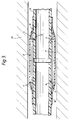
- Figure 3 is a cross sectional view of the device of figure 2 installed in a channel in the ground 20. It will be seen from this figure that the flush profile of this coupler means that very little clearance is needed between the outer surface of the feedthrough sections and the wall of the channel. This figure also shows penetration by the end members 14 into the surface of the feedthrough section. The flush profile also assists the coupler to pass through the type of digging machinery frequently used for laying conduits in trenches in the ground.
Landscapes
- Engineering & Computer Science (AREA)
- General Engineering & Computer Science (AREA)
- Mechanical Engineering (AREA)
- Lining Or Joining Of Plastics Or The Like (AREA)
- Quick-Acting Or Multi-Walled Pipe Joints (AREA)
- Flanged Joints, Insulating Joints, And Other Joints (AREA)
- Rigid Pipes And Flexible Pipes (AREA)
- Photoreceptors In Electrophotography (AREA)
- Pharmaceuticals Containing Other Organic And Inorganic Compounds (AREA)
Abstract
Description
- This invention relates to a coupler for joining elongate substrates, especially pipes, more especially polymeric pipes.
- There are a number of different methods for joining polymeric pipes known in the field. These fall into various categories, for example mechanical couplers, adhesive couplings, direct welding or fusion of the pipes eg by mirror welding or butt fusion, and the use of heat-recoverable polymeric and metallic coupling sleeves.
- A recoverable coupling sleeve is a coupling sleeve whose dimensional configuration may be made to change when subjected to an appropriate treatment. Usually these coupling sleeves recover towards an original shape from which they have previously been deformed, but the term "recoverable" also includes an article which adopts a new configuration even if it has not been previously deformed. The coupler is typically heat recoverable, so that its dimensional configuration may be made to change when subjected to heat treatment. Usually the coupler is radially heat shrinkable.
- US 4141576 (Lupke) is an example of a patent which describes a heat shrinkable polymeric coupling sleeve. In that patent the sleeve is shrunk into frictional engagement with two pipe ends. US 3847694 (Stewing) is similar describing a heat shrinkable resin sleeve used in conjunction with adhesive to join two pipes.
- GB 1327442 describes a heat-shrinkable memory metal coupler sleeve. Memory metals exhibit useful dimensional changes during phase transformations, and hence can be used to make recoverable articles. The coupler exemplified has teeth on its inner surface which preferably partially deform the tubes to be jointed to make the coupling.
- Particular problems are encountered with couplers for elongate substrates for particular applications where a slim outer profile is desirable. For example where a hollow feedthrough is to be provided, eg for a duct in a wall, it is often desirable to provide the feedthrough from joined tubular lengths, rather than from one long tubular member. The outer diameter of the feedthrough is typically only slightly smaller than the inner diameter of the duct, so this means that bulky couplers can not be used. Also for feedthrough applications the joined tubular lengths will be subject to a tensile stress as the feedthrough is pulled through the duct. Thus the coupler must not only be slim, but must also be capable of withstanding high tensile stresses.
- Other couplers, which are not heat shrinkable, are known. For example, GB-A- 960994 describes an attachment for a tube, pipe, rod or like member, by means of which such members can be coupled. The attachment has an internal shouldered socket opening arranged to receive an end of the member together with a packing or sealing ring which encircles the inserted member end. The attachment also has at least one pressure element extending through the wall of the coupling, the orientation and shape of which permits the exertion simultaneously directly of a radial pressure on the external wall of the member and indirectly of an axial pressure on an annular packing secured against the shoulder of the coupling. The or each pressure element is a screw which is tightened into gripping engagement with the member in a direction either perpendicular, or at 45°, to the member.
- US-A-4288114 describes a fitting for connecting pipes, having a generally cylindrical socket section sized to receive and cradle a pipe end, and locking devices extensible into the socket section for securing the pipe ends to the fitting. The locking devices each comprise a shaft body and a tip end, and are driven towards the pipes in a direction perpendicular to the pipes. In one embodiment, each locking device is retained in a ready-to-use position against the bias of a coil spring which biases the locking device towards the pipe. This retention is achieved by means of a washer having a central opening of lesser diameter than the tip end of the locking device. In order to employ the locking devices, they are struck with a hammer or like driving tool so that the tip ends pierce through the washers and through the pipe side walls.
- In both GB-A-960994 and US-A-4288114, elongate devices (pressure elements and locking devices, respectively) extend laterally from the coupler body. Therefore, these known couplers cannot be used for many applications in which the available space around the pipe is limited.
- We have discovered a new coupler and method of joining a polymeric elongate substrate to another substrate, particularly for joining lengths of a feedthrough to each other. The coupler provides a slim connection and is provided with a penetrating member which preferably with the addition of heat, penetrates the outer surface of the polymeric elongate substrate, to provide tensile strength.
- A coupler for joining together two polymeric elongate substrates comprises, according to the invention :
- (a) a tubular element for receiving within it such substrates;
- (b) at least one penetrating member secured to the outside of the tubular element, the or each said penetrating member having at least one penetrating portion for penetrating and engaging the elongate substrates at least two penetrating portions being longitudinally spaced along the tubular element so as to engage different substrates, the tubular element having at least two longitudinally spaced apertures through which the penetrating portions can extend in a working position so as to penetrate and engage the elongate substrates; the or each said penetrating member being an elongate member, the main length of which extends, in its working position, substantially parallel to the tubular element; and
- (c) one or more restraining members for maintaining the penetrating portions in a rest position in which they do not engage the elongate substrates but which can be actuated to allow the penetrating portions to move from the rest position to a working position.
- A second aspect of the invention provides a method of joining a polymeric elongate substrate to another substrate comprising
- (a) positioning one end of the coupler according to the invention over the end of the elongate substrate; and
- (b) causing the or each penetrating member to move from the rest to to the working position.
- The portion of the penetrating member which penetrates the surface of the substrate is preferably, but not necessarily, an end portion.
- Preferably the coupler of the invention is used to join two polymeric elongate substrates, for example two sections of a feedthrough, in an end to end configuration. In this case the tubular element preferably comprises at least two longitudinally spaced apertures which can be arranged in use to overlie respective elongate substrates. A penetrating member is therefore needed for each aperture. Thus either a single penetrating member is used having two end portions each of which is arranged to pass through respective apertures, and having an intermediate part of the penetrating member which is secured to the tubular element, or two separate penetrating members are provided, each having one or more end portions that can pass through respective apertures and being separately secured to the tubular element.
- The penetrating member may have any convenient shape, but is preferably an elongate strip or rod, having a length at at least one end which extends at an angle to the main length of the strip. Thus in its working position the main length of the strip preferably extends substantially parallel to the tubular element, and an end length extends at an angle, ie it is arranged to pass through the aperture in the tubular member. Preferably the penetrating member is made from a resiliently biased material, for example from a spring metal such as spring steel. The resiliently biased member is preferably biased into its working position, and held against its bias in its rest position. Thus the relaxed state of the biased penetrating member corresponds to its working position, and the restrained state of the biased penetrating member corresponds to its rest position. Maintaining the member in its rest position is preferably achieved by a restraining member, which can be released so that the member springs back to its working position. As an alternative, the penetrating member may be made, for example, from a memory metal member, which may be heated to cause the member to move from its rest to working position.
- In another embodiment, the penetrating member may comprise a C-shaped spring member which extends circumferentially around the tubular element, and has one or more radially-directed teeth which can pass through circumferentially spaced apertures in the tubular element. The spring member may be resiliently biased, a bi-metallic element, or a memory metal.
- Where a resiliently biased penetrating member is used, the restraining member to hold it in its rest position preferably comprises a removable restraint, for example a wedge. Where the penetrating member is an elongate strip, which is fixed at one point to the tubular element,it is preferably biased so that, in its released working position, the main length of the strip extends substantially parallel to the tubular element. In this case, the wedge is preferably positioned adjacent the point of fixing to the tubular element, to force the main length of the penetrating member, in its rest position, to extend at an angle to the tubular element. The wedge is thus preferably positioned between the penetrating member and the tubular element. When the wedge is released, the resilient biased penetrating member is arranged to spring back so that its main length lies substantially flush with the tubular element, with the angled end of the penetrating member passing through the aperture in the tubular element. As an alternative to a wedge any other mechanical stopping device may be used to hold the penetrating member in its rest position. As another example of restraining member, a meltable mass can be used, which for example flows on the application of heat to allow the resilient penetrating member to spring to its working position.
- Preferably both the tubular element and the penetrating member comprise a metal. The penetrating member is preferably secured to the tubular element by welding.
- In order to increase the pull-out strengths of the coupler it is preferable to arrange a number of penetrating members around the circumference of the tubular element. Therefore in a preferred embodiment the tubular element of the coupler comprises two or more circumferentially spaced apertures, each having an associated end of a respective penetrating member which can pass through it.
- A particularly preferred construction of penetrating member, for joining two polymeric conduits, comprises a strip of spring steel which is welded towards its centre to the tubular element, and which extends generally parallel to the axis of the tubular element. The strip is resiliently biased to lie flush with the tubular element. However the length of strip on either side of the weld can be directed at an angle away from the tubular element by positioning two wedges, one on either side of the weld, between the penetrating member and the tubular element. Thus, with the wedge in position, the penetrating member forms a shallow "V" shape on the surface of the tubular element. Each end of the penetrating member is angled in a direction towards the tubular element, so that when the wedge is removed, and the penetrating member springs back to its relaxed working position the angled ends pass through the apertures in the tubular elements.
- In a preferred method according to the invention heat is preferably applied to the penetrating member, at least in the region adjacent to the apertures. Contact of the hot penetrating member with the polymeric outer surface of the substrate causes local softening, which facilitates penetration of the substrate by the penetrating member. The heat may be provided by any suitable source, but is preferably applied externally, for example with a gas torch. Where the restraining member comprises a meltable mass, or where the penetrating member comprises a memory metal, the heat applied may also be used to recover the memory metal or to melt the mass.
- The depth of penetration of the end of the penetrating member affects the tensile strength of the coupling. Preferably the end penetrates at least 75% through the depth of the polymeric substrate.
- Where a sealed coupling is required, the invention also provides for a sealing cover to be positioned around the tubular element after the penetrating member has been moved from its rest to working position. Preferably the sealing cover is a heat recoverable, preferably heat shrinkable polymeric sleeve, which is heated, for example with a gas torch, to seal it over the tubular element and also to extend beyond the end of the tubular element on to the elongate substrate. This additional sealing is particularly useful for the application as a coupler for lengths of a feedthrough or duct, where the contents of the feedthrough or duct are to be protected from exterior environmental contamination.
- A heat recoverable sleeve may be positioned around the coupler for other purposes, or in addition to its sealing function. Thus the sleeve can render the joint pressure tight (which is necessary if a pulling wire is to be blown down the duct), it can improve the axial strength of the coupler and it can apply pressure to the penetrating member to improve penetration or resist pull-out forces.
- Thus the invention provides a coupler and a method which is particularly applicable for joining lengths of a feedthrough. The activation of the penetrating members provides a coupling with good tensile strength, and the preferred additional sealing sleeve provides protection from contamination from the environment.
- An embodiment of the invention will now be described, by way of example, with reference to the accompanying drawings, wherein:
- Figure 1 is a perspective view showing a coupler according to the invention in position ready to join two feedthrough conduits in end to end relationship;
- Figure 2 is a perspective view, showing the coupler of figure 1 installed to join the feedthrough conduits together, in combination with an outer sealing sleeve; and
- Figure 3 is a longitudinal sectional view, showing the coupler and sleeve of figure 2 joining the two feedthrough conduits, installed within a duct in a wall.
- Referring now to the drawings, figure 1 shows a
coupler 2 comprising atubular element 4 containingaperture 6 and apenetrating element 8. The are fourapertures 6 in thetubular element 4, there being two at each end of thetubular element 4, diametrically opposed to each other. The penetratingmember 8 comprises a strip of spring steel, which is welded to thetubular element 4 atweld line 10, which is half-way along its length. The springsteel penetrating member 8 is biased so that its main length lies substantially flush with the surface of the tubular element 4.in its working, relaxed position. However,wedges 12 are positioned adjacent theweld line 10 between the penetratingmember strip 8 and the outer surface of thetubular element 4. Thesewedges 12 cause the penetratingmember 8 to extend away from the surface of the tubular element, so that the penetrating member forms an open "V" shape centred on theweld line 10. Each end length of the penetratingmember 8 is angled downward towards the surface of thetubular element 4 at an angle of from 70° to 90°. The length of the penetrating member is arranged so that when thewedges 12 are removed the main length of the penetratingmember 8 springs flush with thetubular element 4, and the angled ends 14 of the penetrating member pass through theaperture 6 in the tubular element. The angled ends may be provided with one ormore teeth 17 to assist penetration. The coupler is positioned around a butt joint between twopolymeric feedthrough conduits 16. One pair ofapertures 6 overlie the first conduit, and the other pair overlie the other conduit. - In order to install the coupler of figure 1, the
wedges 12 are preferably removed, and simultaneously or before, the surface of the penetrating member in the region of theaperture 6 is preferably heated so that when the angled ends 14 contact the surface of the polymer it is softened. This heat is preferably provided by gas torch. - Figure 2 shows the coupler of figure 1 with the
wedges 12 removed, after heating of thepolymer conduit 16. The angled ends 14 have passed into theaperture 6, and penetrated the outer surface of thepolymer conduit 16. An outer heat shrinkablesleeve 18 has been installed around thecoupler 2 and thepolymer conduits 16 in order to provide sealing. Thesleeve 18 extends beyond the ends of thecoupler 2 and over the surface of thepolymer conduits 16. - Figure 3 is a cross sectional view of the device of figure 2 installed in a channel in the
ground 20. It will be seen from this figure that the flush profile of this coupler means that very little clearance is needed between the outer surface of the feedthrough sections and the wall of the channel. This figure also shows penetration by theend members 14 into the surface of the feedthrough section. The flush profile also assists the coupler to pass through the type of digging machinery frequently used for laying conduits in trenches in the ground.
Claims (15)
- A coupler (2) for joining together two polymeric elongate substrates (16) which comprises:(a) a tubular element (4) for receiving within it such substrates (16);(b) at least one penetrating member secured to the outside of the tubular element (8), the or each said penetrating member (8) having at least one penetrating portion (14) for penetrating and engaging the elongate substrates (16) at least two penetrating portions being longitudinally spaced along the tubular element so as to engage different substrates, the tubular element (4) having at least two longitudinally spaced apertures (6) through which the penetrating portions (14) can extend in a working position so as to penetrate and engage the elongate substrates (16); the or each said penetrating member (8) being an elongate member, the main length of which extends, in its working position, substantially parallel to the tubular element (4); and(c) one or more restraining members (12) for maintaining the penetrating portions (14) in a rest position in which they do not engage the elongate substrates (16) but which can be actuated to allow the penetrating portions (14) to move from the rest position to a working position.
- A coupler (2) according to claim 1, in which at least one of the penetrating portions (14) comprises an end portion of a said penetrating member (8).
- A coupler (2) according to claim 1 or 2, wherein the main length of the or each penetrating member (8) extends, in its working position, substantially flush with the outer surface of the tubular element (4), and the or each penetrating portion (14) thereof comprises an end of the penetrating member (8) which is angled towards the tubular element, so that, in the working position, it passes through a said aperture (6) in the tubular element.
- A coupler (2) according to claim 3, in which the angle between the main length and the end of the or each penetrating member (8) is from 70° to 90°.
- A coupler (2) according to any preceding claim wherein the or each penetrating member (8) comprises a resiliently biased member which is held against its bias in the rest position, by the or each restraining member (12), and which when released is biased into the working position.
- A coupler (2) according to claim 5 wherein the or each restraining member (12) comprises a removable restraint, preferably a wedge, or a meltable mass.
- A coupler (2) according to any preceding claim wherein the tubular element (4) and the or each penetrating member (8) comprise metal, and wherein the or each penetrating member is preferably secured to the tubular element by welding.
- A coupler (2) according to any preceding claim comprising two or more circumferentially spaced apertures (6), each with an associated end of a penetrating member (8) which can pass therethrough.
- A coupler (2) according to any preceding claim additionally comprising a heat recoverable, preferably polymeric, sleeve (18).
- A coupler (2) according to any preceding claim, in which the or each penetrating portion (14) is provided with one or more teeth.
- A method of joining a polymeric elongate substrate (16) to another substrate (16) comprising (a) positioning one end of the coupler (2) according to any preceding claim over the end of the elongate substrate and
(b) causing the or each penetrating member (18) to move from the rest to the working position. - A method according to claim 11, comprising the additional step of applying heat to the or each penetrating member (8), at least in the regions adjacent to the apertures (6) in the tubular element (14).
- A method according to claim 12, wherein the heat is applied by an external heat source, preferably a gas torch.
- A method according to claim 11, 12 or 13, wherein the or each penetrating member (8) comprises a resiliently biased member which is held against its bias in its rest position by the restraining member (12), wherein the method comprises moving or removing the restraining member to release the penetrating member, thereby causing it to move from its rest to its working position.
- A method according to any of claims 11 to 14 comprising recovering a heat recoverable, preferably polymeric sleeve (18) over the polymeric elongate substrates (6) and coupler (2), after the penetration of the substrate has taken place.
Applications Claiming Priority (3)
| Application Number | Priority Date | Filing Date | Title |
|---|---|---|---|
| GB909020581A GB9020581D0 (en) | 1990-09-20 | 1990-09-20 | Coupler for elongate substrates |
| GB9020581 | 1990-09-20 | ||
| PCT/GB1991/001607 WO1992005382A1 (en) | 1990-09-20 | 1991-09-19 | Coupler for elongated elements |
Publications (2)
| Publication Number | Publication Date |
|---|---|
| EP0549658A1 EP0549658A1 (en) | 1993-07-07 |
| EP0549658B1 true EP0549658B1 (en) | 1995-11-15 |
Family
ID=10682520
Family Applications (1)
| Application Number | Title | Priority Date | Filing Date |
|---|---|---|---|
| EP91916673A Expired - Lifetime EP0549658B1 (en) | 1990-09-20 | 1991-09-19 | Coupler for elongated elements |
Country Status (8)
| Country | Link |
|---|---|
| US (1) | US5409268A (en) |
| EP (1) | EP0549658B1 (en) |
| AT (1) | ATE130417T1 (en) |
| CA (1) | CA2091164A1 (en) |
| DE (1) | DE69114715T2 (en) |
| ES (1) | ES2082228T3 (en) |
| GB (1) | GB9020581D0 (en) |
| WO (1) | WO1992005382A1 (en) |
Families Citing this family (7)
| Publication number | Priority date | Publication date | Assignee | Title |
|---|---|---|---|---|
| US5662362A (en) * | 1995-11-13 | 1997-09-02 | Advanced Metal Components, Inc. | Swage coupling including disposable shape memory alloy actuator |
| US6085467A (en) * | 1997-07-19 | 2000-07-11 | Stellar Holdings, Inc. | Stackable case to tower conversion |
| DE10230851B4 (en) * | 2002-07-04 | 2009-07-09 | Hansgrohe Ag | plumbing fixture |
| FR2865509B1 (en) * | 2004-01-23 | 2006-04-28 | Maurice Fallavier | POLYGONAL DEVICE FOR FASTENING A AXIS |
| ES2321893B1 (en) * | 2006-05-17 | 2010-04-06 | Akaba, S.A. | UNION DEVICE BETWEEN PROFILES. |
| EP3564568B1 (en) * | 2018-05-02 | 2020-03-25 | Wenz Kunststoff GmbH & Co. KG | Quick connector |
| CN217336640U (en) * | 2022-05-07 | 2022-09-02 | 叶丽芬 | Sectional type arched shed for completing connection by tension |
Citations (2)
| Publication number | Priority date | Publication date | Assignee | Title |
|---|---|---|---|---|
| GB960664A (en) * | 1961-03-15 | 1964-06-10 | Cie Parisienne Outil Air Compr | An attachment for tubes, pipes, rods or like members |
| US4288114A (en) * | 1979-11-28 | 1981-09-08 | Meyertech Incorporated | Fitting with biased locking device for coupling pipes |
Family Cites Families (11)
| Publication number | Priority date | Publication date | Assignee | Title |
|---|---|---|---|---|
| US442837A (en) * | 1890-12-16 | Pipe-coupling | ||
| US937437A (en) * | 1909-03-12 | 1909-10-19 | Hazard Halstead | Hose-coupling. |
| DE329139C (en) * | 1919-12-02 | 1920-11-15 | Siemens Schuckertwerke G M B H | Depth pointer illumination |
| GB248162A (en) * | 1925-02-12 | 1926-03-04 | Kenneth Francis Malcolm Murray | Improvements in hose connectors |
| US2336656A (en) * | 1942-03-30 | 1943-12-14 | John H Van Uum | Snap fastening device for anchoring conduits and the like |
| CH329139A (en) * | 1954-07-10 | 1958-04-15 | Edelstaal Mij N V | Hose connectors, in particular for repair purposes |
| DE2756024C3 (en) * | 1977-12-15 | 1980-08-14 | Philipp Kreis Gmbh & Co Truma-Geraetebau, 8000 Muenchen | Socket pipe fitting for air heating lines or the like |
| US4711472A (en) * | 1986-09-02 | 1987-12-08 | Hubbell Incorporated | Connector for non-metallic conduit |
| US4743079A (en) * | 1986-09-29 | 1988-05-10 | The Boeing Company | Clamping device utilizing a shape memory alloy |
| US4834423A (en) * | 1987-12-22 | 1989-05-30 | Schmelzer Corporation | Quick connect fluid fitting assembly |
| US4944537A (en) * | 1988-06-13 | 1990-07-31 | Usui Kokusai Sangyo Kaisha Ltd. | Small-diameter pipe connector |
-
1990
- 1990-09-20 GB GB909020581A patent/GB9020581D0/en active Pending
-
1991
- 1991-09-19 CA CA002091164A patent/CA2091164A1/en not_active Abandoned
- 1991-09-19 ES ES91916673T patent/ES2082228T3/en not_active Expired - Lifetime
- 1991-09-19 WO PCT/GB1991/001607 patent/WO1992005382A1/en not_active Ceased
- 1991-09-19 AT AT91916673T patent/ATE130417T1/en not_active IP Right Cessation
- 1991-09-19 EP EP91916673A patent/EP0549658B1/en not_active Expired - Lifetime
- 1991-09-19 DE DE69114715T patent/DE69114715T2/en not_active Expired - Fee Related
- 1991-09-19 US US08/030,362 patent/US5409268A/en not_active Expired - Fee Related
Patent Citations (2)
| Publication number | Priority date | Publication date | Assignee | Title |
|---|---|---|---|---|
| GB960664A (en) * | 1961-03-15 | 1964-06-10 | Cie Parisienne Outil Air Compr | An attachment for tubes, pipes, rods or like members |
| US4288114A (en) * | 1979-11-28 | 1981-09-08 | Meyertech Incorporated | Fitting with biased locking device for coupling pipes |
Also Published As
| Publication number | Publication date |
|---|---|
| DE69114715T2 (en) | 1996-07-18 |
| EP0549658A1 (en) | 1993-07-07 |
| ES2082228T3 (en) | 1996-03-16 |
| DE69114715D1 (en) | 1995-12-21 |
| US5409268A (en) | 1995-04-25 |
| CA2091164A1 (en) | 1992-03-21 |
| GB9020581D0 (en) | 1990-10-31 |
| WO1992005382A1 (en) | 1992-04-02 |
| ATE130417T1 (en) | 1995-12-15 |
Similar Documents
| Publication | Publication Date | Title |
|---|---|---|
| US4386796A (en) | Pipe repair coupling | |
| SU799679A3 (en) | Fast-dismountable joint | |
| US3689114A (en) | Sleeve for coupling two sections of duct or conduit | |
| US4039210A (en) | Coupling adapter for plastic pipe | |
| US5348211A (en) | Joining of metallic pipe lined with thermoplastic polymer | |
| US5988691A (en) | Fluid pipelines | |
| US5088772A (en) | Joining insulated elongate conduit members | |
| JPS5830586A (en) | Pipe joint | |
| GB2287996A (en) | Joining thermoplastic pipe to a coupling | |
| JP2009513886A (en) | Plug fitting | |
| US4648626A (en) | Telescopic joint for repairing underwater pipelines laid at a great depth | |
| GB2349189A (en) | Pipe collar | |
| US5409268A (en) | Coupler for elongate substrates | |
| CA2407748A1 (en) | Method and apparatus for end-to-end welding of lined pipe | |
| EP0606224A1 (en) | Method and means for establishing a drawproof insertion joint between thin walled pipes | |
| JPH1163360A (en) | Branch pipe joint device and branch pipe joint reinforcing member | |
| JP2019044942A (en) | Clamping device for electrofusion, electrofusion assembly and method of assembling the same, and electrofusion method | |
| EP0420961B1 (en) | Recoverable sleeve assembly for pipe joint | |
| JP4552000B2 (en) | Renewal or rehabilitation method using insertion pipe with branch joint and branch joint for insertion | |
| JPH04171392A (en) | Electrically fused pipe joint | |
| JPH062797A (en) | Heat fusion joint | |
| DE3860398D1 (en) | CLUTCH DEVICE. | |
| JPH09242973A (en) | Fusion joint with clamp | |
| JP3167209B2 (en) | How to connect steel pipes | |
| JPH0784913B2 (en) | Metal tube connection method |
Legal Events
| Date | Code | Title | Description |
|---|---|---|---|
| PUAI | Public reference made under article 153(3) epc to a published international application that has entered the european phase |
Free format text: ORIGINAL CODE: 0009012 |
|
| 17P | Request for examination filed |
Effective date: 19930313 |
|
| AK | Designated contracting states |
Kind code of ref document: A1 Designated state(s): AT BE CH DE DK ES FR GB GR IT LI NL SE |
|
| 17Q | First examination report despatched |
Effective date: 19940511 |
|
| RAP1 | Party data changed (applicant data changed or rights of an application transferred) |
Owner name: N.V. RAYCHEM S.A. |
|
| GRAA | (expected) grant |
Free format text: ORIGINAL CODE: 0009210 |
|
| AK | Designated contracting states |
Kind code of ref document: B1 Designated state(s): AT BE CH DE DK ES FR GB GR IT LI NL SE |
|
| PG25 | Lapsed in a contracting state [announced via postgrant information from national office to epo] |
Ref country code: LI Effective date: 19951115 Ref country code: GR Free format text: LAPSE BECAUSE OF FAILURE TO SUBMIT A TRANSLATION OF THE DESCRIPTION OR TO PAY THE FEE WITHIN THE PRESCRIBED TIME-LIMIT Effective date: 19951115 Ref country code: DK Effective date: 19951115 Ref country code: CH Effective date: 19951115 Ref country code: AT Effective date: 19951115 |
|
| REF | Corresponds to: |
Ref document number: 130417 Country of ref document: AT Date of ref document: 19951215 Kind code of ref document: T |
|
| REF | Corresponds to: |
Ref document number: 69114715 Country of ref document: DE Date of ref document: 19951221 |
|
| ITF | It: translation for a ep patent filed | ||
| PG25 | Lapsed in a contracting state [announced via postgrant information from national office to epo] |
Ref country code: SE Effective date: 19960215 |
|
| ET | Fr: translation filed | ||
| REG | Reference to a national code |
Ref country code: ES Ref legal event code: FG2A Ref document number: 2082228 Country of ref document: ES Kind code of ref document: T3 |
|
| REG | Reference to a national code |
Ref country code: CH Ref legal event code: PL |
|
| PLBE | No opposition filed within time limit |
Free format text: ORIGINAL CODE: 0009261 |
|
| STAA | Information on the status of an ep patent application or granted ep patent |
Free format text: STATUS: NO OPPOSITION FILED WITHIN TIME LIMIT |
|
| 26N | No opposition filed | ||
| PGFP | Annual fee paid to national office [announced via postgrant information from national office to epo] |
Ref country code: FR Payment date: 19970909 Year of fee payment: 7 |
|
| PGFP | Annual fee paid to national office [announced via postgrant information from national office to epo] |
Ref country code: GB Payment date: 19970910 Year of fee payment: 7 |
|
| PGFP | Annual fee paid to national office [announced via postgrant information from national office to epo] |
Ref country code: ES Payment date: 19970926 Year of fee payment: 7 |
|
| PGFP | Annual fee paid to national office [announced via postgrant information from national office to epo] |
Ref country code: NL Payment date: 19970929 Year of fee payment: 7 |
|
| PGFP | Annual fee paid to national office [announced via postgrant information from national office to epo] |
Ref country code: BE Payment date: 19971118 Year of fee payment: 7 |
|
| PG25 | Lapsed in a contracting state [announced via postgrant information from national office to epo] |
Ref country code: GB Free format text: LAPSE BECAUSE OF NON-PAYMENT OF DUE FEES Effective date: 19980919 |
|
| PG25 | Lapsed in a contracting state [announced via postgrant information from national office to epo] |
Ref country code: ES Free format text: LAPSE BECAUSE OF NON-PAYMENT OF DUE FEES Effective date: 19980920 |
|
| PG25 | Lapsed in a contracting state [announced via postgrant information from national office to epo] |
Ref country code: BE Free format text: LAPSE BECAUSE OF NON-PAYMENT OF DUE FEES Effective date: 19980930 |
|
| BERE | Be: lapsed |
Owner name: S.A. RAYCHEM N.V. Effective date: 19980930 |
|
| PG25 | Lapsed in a contracting state [announced via postgrant information from national office to epo] |
Ref country code: NL Free format text: LAPSE BECAUSE OF NON-PAYMENT OF DUE FEES Effective date: 19990401 |
|
| GBPC | Gb: european patent ceased through non-payment of renewal fee |
Effective date: 19980919 |
|
| PG25 | Lapsed in a contracting state [announced via postgrant information from national office to epo] |
Ref country code: FR Free format text: LAPSE BECAUSE OF NON-PAYMENT OF DUE FEES Effective date: 19990531 |
|
| NLV4 | Nl: lapsed or anulled due to non-payment of the annual fee |
Effective date: 19990401 |
|
| REG | Reference to a national code |
Ref country code: FR Ref legal event code: ST |
|
| REG | Reference to a national code |
Ref country code: ES Ref legal event code: FD2A Effective date: 19991013 |
|
| PG25 | Lapsed in a contracting state [announced via postgrant information from national office to epo] |
Ref country code: IT Free format text: LAPSE BECAUSE OF NON-PAYMENT OF DUE FEES;WARNING: LAPSES OF ITALIAN PATENTS WITH EFFECTIVE DATE BEFORE 2007 MAY HAVE OCCURRED AT ANY TIME BEFORE 2007. THE CORRECT EFFECTIVE DATE MAY BE DIFFERENT FROM THE ONE RECORDED. Effective date: 20050919 |
|
| PGFP | Annual fee paid to national office [announced via postgrant information from national office to epo] |
Ref country code: DE Payment date: 20051031 Year of fee payment: 15 |
|
| PG25 | Lapsed in a contracting state [announced via postgrant information from national office to epo] |
Ref country code: DE Free format text: LAPSE BECAUSE OF NON-PAYMENT OF DUE FEES Effective date: 20070403 |