EP0549314A1 - Enhanced fidelity reproduction of images by hierarchical template matching - Google Patents
Enhanced fidelity reproduction of images by hierarchical template matching Download PDFInfo
- Publication number
- EP0549314A1 EP0549314A1 EP92311669A EP92311669A EP0549314A1 EP 0549314 A1 EP0549314 A1 EP 0549314A1 EP 92311669 A EP92311669 A EP 92311669A EP 92311669 A EP92311669 A EP 92311669A EP 0549314 A1 EP0549314 A1 EP 0549314A1
- Authority
- EP
- European Patent Office
- Prior art keywords
- pixel
- pattern
- pixels
- image
- patterns
- Prior art date
- Legal status (The legal status is an assumption and is not a legal conclusion. Google has not performed a legal analysis and makes no representation as to the accuracy of the status listed.)
- Granted
Links
Images


Classifications
-
- G—PHYSICS
- G06—COMPUTING; CALCULATING OR COUNTING
- G06K—GRAPHICAL DATA READING; PRESENTATION OF DATA; RECORD CARRIERS; HANDLING RECORD CARRIERS
- G06K15/00—Arrangements for producing a permanent visual presentation of the output data, e.g. computer output printers
Landscapes
- Engineering & Computer Science (AREA)
- General Engineering & Computer Science (AREA)
- Physics & Mathematics (AREA)
- General Physics & Mathematics (AREA)
- Theoretical Computer Science (AREA)
- Facsimile Image Signal Circuits (AREA)
- Fax Reproducing Arrangements (AREA)
- Image Analysis (AREA)
- Dot-Matrix Printers And Others (AREA)
- Laser Beam Printer (AREA)
Abstract
Description
- The present invention relates to improvement in the display of raster images, and in particular to enhancing the exposure fidelity in increased precision optical display systems. More specifically, the invention pertains to economical and technically attractive methods and means for enhancing the contour fidelity of exposures on a microaddressable optical printer.
- Others have proposed template matching techniques for more precisely controlling the size, positioning and number of picture elements ("pixels") that are printed on a xerographic photoreceptor to render bitmapped images.
- Walsh et al., US-A-4,437,122, describes a method of enhancing the resolution and quality of characters of a system receiving video display pixel information and providing hard copy output. The system accomplishes this by storing at least three successive lines of video data in successive parallel connected shift registers, applying the output of the shift registers to a decoder, and generating driving signals for a printer head. As described in
column 2, lines 6-10, the decoder "compares the pixels on the same line as well as in preceding and succeeding lines that surround each specific input pixel to generate the printer head driving signal according to whether straight or curved line segments are to be formed." As described incolumn 3, line 67, tocolumn 4,line 1, the enhancement of the central pixel may be determined by "progressively examining an ordered table of matches to find an equivalent image and its related enhancement." - Tung, US-A-4,847,641, describes a technique for enhancing the printing of bitmapped images by piecewise matching of the bitmap with predetermined stored templates of patterns to detect occurrence of preselected bitmap features. Templates representing compound error elements common to all bitmap images, associated compensation signals for each template, and the rules governing the relationships between the matched templates and the associated compensation signals are compiled into an index matching table implemented in a high speed parallel logic array.
- Template matching effectively overcomes some of the sampling errors that are caused by the use of input data that is too coarse to accurately represent the higher spatial frequency content of the image. It does not, however, solve the problems that may be encountered in existing printers due to non-linearity in the way in which the spatial positioning of the transitions in printed images tracks changes in the intensity of the transitional boundary scans.
- Many of the ROSs (raster output scanners) that have been developed for xerographic printing employ a single beam or a multi-beam laser light source for supplying one or more intensity modulated light beams, together with a scanner (such as a polygon scanner) for cyclically deflecting the modulated laser beam or beams across a photoreceptor in a "fast scan direction" while the photoreceptor is being advanced simultaneously in an orthogonal "process direction." In practice, each of the laser beams typically is brought to focus on or near the photoreceptor surface to provide a substantially focused "scan spot." The scan spot, in turn, scans the photo!eceptor in accordance with a predetermined scan pattern because the fast scan deflection of the laser beam or beams vectorially sums with the process direction motion of the photoreceptor. Indeed, the scan pattern is dependent upon and is determined by the scan rate (scan/sec) of the scanner, the spot size that is employed, and the process speed (meters/sec) of the photoreceptor. Such a scan pattern produces an exposure pattern because the scans are superpositioned on the photoreceptor, regardless of whether the scans simultaneously or sequentially expose the photoreceptor. Accordingly, it is to be understood that the present invention applies to printers and other display means that employ single beam or multi-beam ROSs, even though this disclosure features the single beam/single scan spot case for the sake of simplification.
- Microaddressable printers and other types of display systems operate in an overscanned mode to render images by scanning one or more intensity modulated scan spots over a high gamma, photosensitive recording medium in accordance with a scan pattern that causes the spot or spots to superimpose multiple discrete exposures on the recording medium on centers that are separated by a pitch distance that is significantly less than the effective spatial diameter of the scan spot (i.e., the full width/half maximum (FWHM) diameter of a gaussian scan spot). Overscanned systems have substantially linear addressability responses, so boundary scans that are intensity modulated in accordance with the preselected offset values are used by these systems for spatially positioning the transitions that are contained by the images they render to a sub-pitch precision.
- With older techniques of FWHM printing, the output resolution is limited to the scan resolution. With double overscanned printing, there are twice as many scans, effectively doubling the resolution scans in the process direction. The power to the laser diode, or "intensity" of each scan, can be controlled during the scan, giving subscan addressability. For example, in a printer with a spot size of 63 µm, scanning would take place at 32 scans per mm. At four levels of gray, the addressability of the printer increased to 128 bits per mm.
- Overscanning that results from the use of finer pitch scan patterns degrades the spatial frequency response of the printer in the process direction. A limited overscan is, however, consistent with the printing of high quality images because it permits the image transitions (i.e., the high spatial frequency content of the images) to be mapped onto the scan pattern with increased spatial precision.
- The technique of microaddressability via overscanned illumination is more fully described in our copending European Patent Application No. 92 306 091.7.
- The present invention provides a method for enhancing the contour fidelity of images. The method includes isolating a window of pixels in a portion of the image and comparing pixels in the window with a hierarchical set of standard pixel patterns which include correctable pixel positions. Matching patterns are identified, and the central pixel of the window is enhanced when it lies in a correctable position in the highest priority pattern that is matched.
- The present invention also provides a template matching technique with a double overscanned ROS to achieve enhanced fidelity exposures. Furthermore, the technique of the present invention may compensate for the width of a spot in both the fast scan and process directions. The technique of the present invention serves to smooth contours and jagged or stair-stepped edges commonly found in bitmapped images.
- One aspect of the invention is based on the recognition of a problem with conventiona) and overscanned printing utilized to render enhanced exposure fidelity to a photoreceptor or other recording media. Normally the source of the high fidelity information is a sampled image or a high resolution bitmap. But many raster data sources provide low resolution bitmaps at 12 or 16 bits per mm, which is not enough resolution to eliminate unwanted artifacts induced by the coarseness of the information, such as stairstepping.
- Another aspect of the invention is based on the recognition of a problem with other techniques in a conventional printer where the scan spacing is the same as the spot resolution, which does not compensate for the width of the spot. This aspect is further based on the discovery that this problem can be solved by an extension to a 2x overscanned printer, which gives the advantage of having a more linear edge positioning response with respect to intensity, thereby reducing the number of required correction intensities, as well as simplifying and making the edge positions more predictable.
- The technique of the invention further compensates for the width of the spot when rendering all bitmapped data, thereby reducing distortion of shapes when the object being rendered is one or two bits wide.
- The hierarchical and permutation strategy of the invention has the advantage of simplifying the implementation. Pattern templates are implemented in a hierarchical arrangement, in which the largest pattern which receives a match will have priority over smaller patterns. Patterns are arranged so that a match on any pattern in general is simply the combination of a match on the next lowest pattern plus two additional bits, saving gate resources in the decoding logic.
- A method for enhancing the contour fidelity of images in accordance with the invention will now be described, by way of example, with reference to the accompanying drawings, in which:-
- Fig. 1 shows general features of a laser printer.
- Fig. 2 shows an application of microaddressability in 2x overscanned output device to a portion of a bitmap.
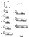
- Fig. 3 shows a set of patterns which represent a hierarchy of patterns for recognition of low fidelity bits which are to be enhanced.
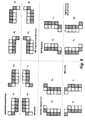
- Fig. 4 shows a set of horizontal and vertical templates based on permutations of
pattern 4 from Fig. 3. - Fig. 5 shows a set of horizontal and vertical templates based on permutations of
impulse match pattern 4 from Fig. 3. - Fig. 6 shows an input window used to determine the area of the image.
- Fig. 7 shows a portion of an image in an input window similar to Fig. 6.
- Fig. 8 illustrates an enhancement application in a group of pixels.
- Fig. 9 shows the resulting enhancement values of pixels in a pattern as a result of the operations shown in Fig. 8.
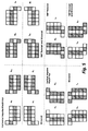
- Fig. 10 shows pixels, indicated in bold, which need to be corrected when horizontal templates are matched.
- Fig. 11 shows pixels, indicated in bold, which need to be corrected when vertical templates are matched.
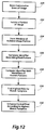
- Fig. 12 shows a flowchart illustrating steps in enhancing a portion of an image.
- Fig. 13 shows an example of multiple templates permutated from
pattern 5 matching a portion of text. - Fig. 14 shows a block diagram of an apparatus for performing the image enhancement in accordance with the present invention.
- Fig. 15 shows a portion of an image.
- Figs. 16-19 show typical implementations of template detecting circuitry.
- Fig. 20 shows an improved circuit implementation which detects matches with hierarchical templates.
- An "image" is a pattern of light. An image may include characters, words, and text as well as other features such as graphics. An "image output device" is a device that can provide an image as output. A "display" is an image output device that provides information in visible form. The visible pattern presented by a display is an "image."
- Each location in an image may be called a "pixel." In an array defining an image in which each item of data provides a value, each value indicating the color or intensity of a location may be called a "pixel value". The two-dimensional array of pixels defining the image may be "binary form" or "bitmapped," or a "gray-scale form." Each pixel value is a "bit" in the binary form or bitmap of the image, or a "gray-scale intensity value" in a gray-scale form of the image. An edge of an image may be described as a "contour" that may have a "slope" or angle.
- Figs. 1 and 2 show general features and application of an overscanned laser printer.
- In Fig. 1, there is illustrated a more or less conventionally configured
optical system 10 of a xerographic print engine (not shown). The flying spot ROS scans a data modulatedlight beam 12 over axerographic photoreceptor 14 in accordance with a predetermined raster scanning pattern. To that end, the ROS comprises alaser diode 16 for emitting thelight beam 12 in the visible or invisible (e.g., infrared) band of the spectrum, together with apolygon scanner 18 that has a plurality of nearly identical, mirror-like exterior sidewalls or "facets" 20. - In keeping with standard practices, there is a
motor 22 for rotating thescanner 18 about its central axis, as indicated by thearrow 24, at a substantially constant angular velocity. Thescanner 18 is optically aligned between thelaser 16 and thephotoreceptor 14, so its rotation causes thelaser beam 12 to be intercepted and reflected from one after another of thescanner facets 20, with the result that thebeam 12 is cyclically swept across thephotoreceptor 14 in a fast scan direction. Thephotoreceptor 14, on the other hand, is advanced (by means not shown) simultaneously in an orthogonal, process direction at a substantially constant linear velocity, as indicated by thearrow 26, so thelaser beam 12 scans thephotoreceptor 14 in accordance with a raster scan pattern. As shown, thephotoreceptor 14 is coated on arotating drum 28, but it will be apparent that it also could be carried by a belt or any other suitable substrate. - Typically, the ROS additionally includes
pre-scan optics 30 andpost-scan optics 32 for bringing thelaser beam 12 to a generally circular focus proximate thephotoreceptor 14 and for providing any optical correction that may be needed to compensate for scanner wobble and other optical irregularities. Preferably, the optical aperture of the ROS is sufficiently large to avoid excessive truncation of thelaser beam 12 because thebeam 12 then comes to a generally circular or elliptical focus with a gaussian intensity profile. However, the broader aspects of this invention are not limited to any specific scan spot geometry or intensity profile. Accepted design principles indicate that the spatial frequency power spectrum of the scan spot profile should not have significant spatial frequency components outside the spatial frequency passband of the imaging system, but the scan spot can otherwise be tailored to satisfy a variety of system requirements. - The amplitude, duty cycle, and/or pulse width of the
laser beam 12 is serially modulated (collectively referred to herein as "intensity modulation") in accordance with successive multi-bit digital data values. These data values are clocked out of adata source 36 serially in response to data clock pulses which are time synchronized with the scan of the scan spot from bitmap location-to-bitmap location within the raster scan pattern. Thus, the data clock frequency can be selected (by means not shown) to map the data onto the raster scan pattern at any desired magnification, using either the same or different magnifications in the fast scan and the process directions. The data may be preprocessed (by- means not shown) for the printing of halftoned images and/or text and other types of line art, so thedata source 36 generically represents any suitable source of raster data for intensity modulating thelaser beam 12. The drive current for thelaser diode 16 is serially modulated bymodulator 38 in accordance with the data values that are clocked out of thedata source 36, thereby intensity modulating thelaser beam 12 at the data clock rate in accordance with those data values. - The fast scan positioning precision of the
print engine 10 can be increased, if desired, by dynamically adjusting the frequency of the data clock to compensate for positioning errors that tend to be caused by "motor hunt" (i.e., variations in the angular velocity of the scanner 18), "polygon signature" characteristics (variations in the angular velocities at which thedifferent facets 20 of thescanner 18 sweep the scan spot across thephotoreceptor 14 from a start-of-scan position to an end-of-scan position), and "scan non-linearities" (i.e., localized variations in the linear velocity of the fast scan, which are caused by variances in the geometric relationship of thescanner 18 to spatially distinct segments of any given scan line). - The pitch of the scan pattern for the
printer 10 is selected to be significantly finer (i.e., smaller) than the FWHM diameter of the scan spot that is formed from thescan beam 12. This relatively fine pitch scan pattern causes theprinter 10 to operate in an "overscanned" mode because the FWHM central core of the scan spot sweeps across spatially overlapping segments of thephotoreceptor 14 during the scanning of spatially adjacent, neighboring scan lines. Overscanning slightly degrades the spatial frequency response of theprinter 10 in the process direction. However, it has been found that the linearity of the addressability response of ROS printers, such asprinter 10, increases rapidly as the ratio of the scan pitch to the FWHM diameter of the scan spot is reduced to progressively smaller, sub-unity values (i.e., increasing the overscan). In other words, it has been found that overscanning is the key to providing the essentially linear position control that enables discrete exposures to map image transitions onto a scan pattern at a sub-resolution precision. Thus, in the printer shown in Fig. 1, a relatively small loss of process direction frequency response is accepted to achieve substantially increased process direction addressability. - Fig. 2 shows an example of the application of microaddressability by overscanning in a 2x overscanned output device.
Central pixel 50 is surrounded by other pixels, such aspixel 52. In this case, thefast scan direction 54 is shown in a horizontal direction, and the slow scan, orprocess direction 58 is shown vertically. In theslow scan direction 58, scantrajectories - Additionally, the addressability in the slow scan direction is increased by another factor of four due to four levels of intensity adjustment in the ROS. In the
fast scan direction 54, the addressability is increased by a factor of four by increasing the clock frequency. Each pixel is thereby represented by eight segments, each of which may have one of four different intensity levels. By compensating for the width of the scan spots at different intensities, the technique may reduce shape distortion when the object being rendered is one or two bits wide. - In this example, if the bitmap input were 16 bits per mm, then the enhanced printer would have 64 addressability in the fast scan direction, and 128 addressability in the slow scan direction. These parameters may be modified depending on target design goals.
- Scan spots 60-66 show example scan spot sizes corresponding to a 2x overscanned printer, as described in our copending European Patent Application No. 92 306 091.7.
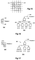
Scan spot 60 shows an example scan spot size corresponding tointensity 1.Scan spot 62 shows an example scan spot size corresponding tointensity 2.Scan spot 64 shows an example scan spot size corresponding tointensity 3.Scan spot 66 shows an example scan spot size corresponding tointensity 4. - Fig. 3 shows a pattern set 70 of "patterns" which represent a hierarchy of patterns for recognition of low fidelity bits which are to be enhanced. Printers or other devices which use template matching can use these patterns to detect edge lines which may be slightly horizontal or slightly vertical. The set is a "hierarchy" of ten patterns, in which the next higher member of the set is a composite of the previous member in the hierarchy and an extension pattern of two additional bits. This method of obtaining patterns saves gate resources in implementation, in that any pattern is simply the combination of the next lower priority pattern plus two additional bits, one "on" and the other "off." In the ten pattern set shown in Fig. 3 the highest priority pattern is
pattern 9, but fewer or more patterns may be utilized. - The patterns are designed to find the slope of portions of edges, or contours, in an image. In the method of the invention the largest, or highest, pattern which receives a match will have priority over smaller patterns, and the enhancement called for by that particular pattern will be utilized. If no pattern matches, then the portion of the image being examined is not an edge, and no enhancement action is taken.
Pattern 0 will be identified as a match at any edge transition from white to black. Higher priority patterns are extensions ofpattern 0, each with two additional bits, which will match edges that are not precisely horizontal or vertical. For example,line 74 shows an edge line that is precisely horizontal which is matched bypattern 0.Pattern 1, which has a "run-length" of 1, will match an edge approximately 45° from horizontal, shown byline 76. As the run-length of patterns increases, the angle of the edge that each pattern will match gets closer to horizontal.Pattern 9 has a run-length of 9. - Each pattern in the hierarchical set may further be used to define a set of templates. Figs. 4 and 5 show a set of templates created from
pattern 4. In Fig. 4,pattern 4 is rotated and mirrored in the horizontal and vertical directions to produce a set of 16 templates. Template ah describes the basic pattern. Template bh is the complement of the basic pattern. Together, these two templates are called an "impulse pair." - When templates ah and bh are rotated 180° another impulse pair is created by templates ch and dh. These four templates are then mirrored, creating two additional impulse pairs made up of templates eh and fh and templates gh and hh.
- Eight additional templates, or 4 impulse pairs, are created when templates ah-hh are rotated 90°. Templates ah-hh are herein referred to as "horizontal " templates, and templates av-hv are herein referred to as "vertical" templates. Templates ah-hh and av-hv are herein referred to as "permutations" of
pattern 4. - A match of both templates of an impulse pair, as shown in Fig. 5, denotes the existence of an "impulse match" denoting a black or white line with a width of one bit. When matches for both templates in an impulse pair occur, they may be treated differently than when only one template from the impulse pair is recognized or if both templates in the pair were matched independently, and different enhancement information may be output. Matches for single templates of an impulse pair denote transitions from black to white or white to black over widths wider than a single bit. A basic impulse match may be rotated and mirrored in both the horizontal and vertical directions in the same way that the basic pattern was in Fig. 4, to create an additional 16 templates.
- Each pattern in the
hierarchical set 70 may be used to create a similar set of 32 templates of different permutations. Additional patterns or combinations of patterns or templates with different extension patterns may be combined to recognize other objects such as crossed lines and corners. - Fig. 6 shows an
input window 80 to be used to determine the area of the image to be matched by the templates. An input window is defined as the area of the input low resolution bitmap over which patterns can be found.Central pixel 82 is the pixel which will receive enhanced correction information.Input window 80 is shown with a size of 11 x 11 pixels. However, size of the input window is important only to the extent that it allows the recognition of all patterns. It may be adjusted up or down in size in the design as required. The technique of the invention makes symmetrical corrections--that is, corrections can be made to the vertical direction with the same precision as in the horizontal direction, to either side of the center point. A window that is as tall as it is wide, with an equal number of pixels along each axis to each side of the center point, is called a "symmetrical" window. For pixels which are near the edge of the image, the side of the window that is truncated by the edge of the image is considered to be filled with "off" pixels. - An input window of size 11 x 11 is appropriate for the hierarchical set of
patterns 70 in Fig. 3.Pattern 6, with a run-length of 6, fits entirely within the window at its first correctable pixel at the center pixel location. It can be shown that patterns of larger run-length, such aspattern 9, will also fit. In consideration of current economics of design and of output resolution capabilities, patterns of run-lengths of greater than 6 may not give discernibly better results than achieved using a hierarchy that includes patterns 0-6. - Fig. 7 shows a portion of an
image 90 ininput window 80. As shown, a portion of the image matchespattern 7, but only theportion matching pattern 6 is visible inside the window.Pixel 82, the central pixel, is in a correctable position for bothpattern pattern 6. As the window shifts locations over the image, other correctable pixels in the pattern may be detected. - Fig. 8 illustrates an enhancement of a group of pixels forming a portion of an image.
Group 110 encompasses a group of pixels that matchespattern 4, permutation ah, as shown in Fig. 4. For this example, it is assumed that this portion of the image does not match any impulse match template (i.e., the width of the image represented in part by the pixel group is greater than 1 pixel wide), or any higher priority template.Lines Marks 126 show the clock frequency in the fast scan direction.Line 132 shows the trajectory of the line of the edge illustrated by the group of pixels.Line 134 shows the corrected edge in the enhancement. The enhanced edge is one half of the maximum spot diameter from the original trajectory. - As discussed above, the central pixel can be divided into eight segments, each with a different gray level or intensity value. The first pixel to be corrected is
pixel 120. In the original image input,pixel 120 is entirely white. The first, or top scan of this pixel will also be entirely white. Correction of the pixel to the enhanced edge will be made in the second, or bottom scan ofpixel 120.Scan spot 136 shows a spot ofintensity 2 that significantly fills in the area between the original trajectory and the enhanced edge to correct the line at the first clock cycle.Scan spot 138 ofintensity 1 significantly fills in the area to the enhanced edge at the second clock cycle.Scan spot 140 also has an intensity of 1 at the third clock cycle. At the fourth clock cycle,mark 142, no correction spot is required because theintensity 4 spots in the black pixel below it significantly fill in the area to the enhanced edge at that location, so the intensity value at that point is zero. The expanded segment pattern of corrected values forpixel 120 is then 0000 and 2110 for the first and second scans, respectively. - Correction may also be made to
pixel 128. At the first clock cycle in the fast scan direction, a scan spot ofintensity 4, shown byscan spot 144, is needed.Scan spot 146 at the second clock cycle has an intensity of 3.Scan spot 148, at the third clock cycle, also has an intensity of 3.Scan spot 150 has an intensity of 2 at the fourth clock cycle. The second scan ofpixel 128 needs no correction, so scan spots ofintensity 4 will be output at each clock cycle. The expanded segment pattern of corrected values ofpixel 128 is then 4332 and 4444 for the first and second scans, respectively. - Fig. 9 shows the resulting expanded pattern of intensity values according to the method performed in Fig. 8. When
pixel 120 is in the central pixel position ofwindow 80 of Fig. 6 when a match withtemplate 4 permutation ah is found, it will be enhanced with segments with gray level intensities of 0 0 0 0 in the first scan, and 2 1 1 0 in the second scan. Similarly, whenpixel 128 is the central pixel, it will be enhanced with segments with gray level intensities of 4 3 3 2 and 4 4 4 4, as shown in Table 1. If a match with this pattern is made whenpixel 130 is in the central pixel position, no enhancements are made according to this pattern and the segment represent the original pixel. However,pixel 130 is likely to fall in the correctable range of another template. - If a different permutation template of
pattern 4 was the highest priority match, Tables 1 or 2 could be used to determine the enhancement values of segments for the central pixel. If a permutation of an impulse match ofpattern 4 was the highest priority match, Tables 3 or 4 could be used to determine the enhancement values of segments for the central pixel. - The results of the kind of operation shown in Figs. 8 and 9 are shown in Table 1. As shown in the table,
pixels pixel 120 are shown in thePixel 2 column in Table 1. Values for pixels which occur in the position ofpixel 128 are shown in thePixel 1 column. - Tables 1-4 show enhancement values of segments for the pixels which will be

enhanced inpattern 4 for different permutations and impulse match permutations.
- Tables 1 and 2 show templates which are permutations of
basic pattern 4, Table 1 showing enhancement values for horizontal permutations, and Table 2 showing enhancement values for vertical permutations. As discussed above, the enhancement value for the central pixel is shown in one of the two columns,Pixel 1 orPixel 2, depending on where in the pattern the central pixel lies. The data in these tables has been determined empirically. Small variations in the intensity of enhancement values of segments are likely to be imperceptible when output. Similarly, patterns which are longer than run-length 6 may not produce perceptibly better enhanced results when output, depending on the resolution of the output medium. - Tables 3 and 4 show enhancement values for the segments for pixels in impulse matches for
pattern 4. For each impulse match template which is permuted frompattern 4, the enhancement values for the central pixel are shown in one of the four columns, according to where in the pattern the central pixel lies. Table 3 shows the values for horizontal impulse match templates, and Table 4 shows the values for vertical impulse match templates. - Figs. 10 and 11 show pixels, in bold outline, which need to be corrected when a template is matched as the highest priority template. Fig. 10 shows the correctable pixel positions for horizontal patterns, and Fig. 11 shows the correctable pixel positions for vertical

patterns. In order for an enhancement to be made, the pixels matching the template must be positioned in theinput window 80 of Fig. 6 such that thecentral pixel 82 is in the position of one of the correctable pixel positions as shown in Figs. 10 or 11. For example, if a horizontal permutation ah, ch, eh, or gh ofpattern 5 is matched in the input window, the pixels in locations corresponding topixels Pixels pixels 
with no enhancement, for example (0000,0000) for an entirely white pixel, or(4444,4444) for an entirely black pixel. - The flowchart of Fig. 12 shows steps in enhancing a portion of an image. The step in
box 220 stores consecutive lines of an image. The step inbox 222 isolates a portion of the image. The step inbox 224 forms a window in the isolated portion of the image. This window may be a symmetrical set of pixels around a central pixel. - The step in
box 226 generates an identifier describing the pixel pattern. The step inbox 228 compares the identifier of the window with the identifiers of known pixel patterns, or templates. The step inbox 230 finds the highest priority template that is matched. The step inbox 232 enhances the central pixel, according to the correction data for the highest priority matched template. If more than one template for a given pattern is detected and a pixel is correctable in both, enhancement information for the template corresponding to the lowest alphanumeric is given priority. - For example, in Fig. 13 a portion of an
image 250 is shown.Template 252 shows that template ah based onpattern 5 matches on the portion of the image.Template 254 shows that template dh ofpattern 5 also matches on the portion of the image. From Fig. 10,pixel 256 falls in a correctable pixel position in bothtemplates template 252, would be used. - Fig. 14 shows a block diagram of an
apparatus 280 for performing the image enhancement in accordance with the present invention.Raster Data Source 282 provides serial raster data toBand Buffer 284, formed byRAM 286 controlled byAddress Counter 288.RAM 286 stores a field of (L x N-1), where L is the number of bits in a line of the input, and N is the height of the input window. The Nth line is shifted directly into the shift register to form an N height window. The number of bits in a line L will vary by the input data source, for example for a CRT the line length may be 1000 bits, but for a large-scale printer the number of bits in a line may be as much as 8000 bits. On a typical laser printer with number of bits per mm of about 12 and 279 mm line, a typical RAM size for implementing an 11 x 11 window may be about (3300 bits x 11 lines).RAM 286 andAddress Counter 288 form a circular band buffer which steps line by line through the input. Alternatively, the band buffer could be made up of a series of shift registers which perform the same function.Band Buffer 284 provides input data lines toTemplate Logic 290. -
Template Logic 290 is made up of a plurality of shift registers 292. There are N shift registers, one for each line of the input window. The shift registers 292 input data intoTemplate Decoding Logic 294 to form the input window. InTemplate Decoding Logic 294, the input window is examined for matches with a hierarchical set of templates.Template Decoding Logic 294 examines primarily the pixels around the center axis of the input window, but data for the entire input window may be received from the shift registers 292.Template Decoding Logic 294 may compare the data with templates either serially or in parallel. The enhanced segment data for the corrected pixel is output fromTemplate Logic 290 to output means 296, which may be a microaddressable display means. - Figs. 15-20 describe methods of implementing
Template Decoding Logic 294. Fig. 15 shows a portion of aninput window 310 with pixel locations labeled A-H. For this example,pixel A 312 is taken to be in the central pixel position. Each pixel location will provide a signal A-H to the template decoding logic describing the bit value of the pixel. - Figs. 16-19 describe a typical way in which templates may be decoded. Fig. 16(a) shows the first template to be decoded in this example, a two pixel template in which the
top pixel 320 has a bit value of "1", and thebottom pixel 322 has a bit value of "0." Fig. 16(b) shows a typical implementation of logic to detect the presence of this template.Gate 324 tests signals A andB. Gates template 1 and none of the other signals match the template, theoutput 334 fromgate 332 will indicate a match fortemplate 1. - Fig. 17(a) shows the second template,
template 2.Circuit 340 in Fig. 17(b) surveys signals A, B, C, and D for a match withtemplate 2. If thesignals match template 2 and signals E, F, G, and H do not indicate a match with the next template, theoutput signal 342 will indicate a match withtemplate 2. The circuit in Fig. 18(b) similarly tests for a match withtemplate 3 in Fig. 18(a), and the circuit in Fig. 19(b) similarly tests for a match withtemplate 4 in Fig. 19(a). Clearly, the circuitry increases exponentially with the size of the template set. - Fig. 20 shows a
circuit 360 that may be employed in the template decoding logic using templates related to patterns similar to set 70 of Fig. 10. The hierarchical nature of the pattern set allows the circuit to build upon itself for each successive pattern in the hierarchy, thereby significantly reducing the number of gates necessary for the implementation.Gate 370 detects a match oftemplate 1 by signals A andB. Gate 374 uses the output ofgate 370 indicating a match oftemplate 1 and input from signals C and D to detect a match oftemplate 2.Gate 380 uses the output ofgate 374 indicating a match oftemplate 2 and input from signals E and F to detect a match oftemplate 3.Gate 386 uses the output ofgate 380 indicating a match oftemplate 3 and input from signals G and H to detect a match oftemplate 4. - If
only template 1 is matched,gate 372 will indicate a match tooutput signal 373. Ifgate 374 indicates a match withtemplate 2, the output signal from 374 will be input togate 378, which will disablegate 372 and inhibit signal 373 from indicating the match withtemplate 1, so only the match with the highest priority template will be indicated. Similarly, if the output signal fromgate 380 indicates a match withtemplate 3,gate 384 will turn off the output ofgate 376 and inhibitsignals template 2 oftemplate 1.Signal 388 output from 386 will also inhibit the previous template match signals ifgate 386 indicates a match withtemplate 4. - Due to the hierarchical nature of pattern types of the invention, the number of gates in
circuit 360 will naturally increase linearly with the size of the template set, rather than exponentially. - In view of the foregoing, it now will be evident that the present invention provides economical and technically attractive methods for enhancing the contour fidelity of exposures in microaddressable display systems. These methods employ hierarchical template matching and spot width compensation techniques to smooth contours and jagged edges commonly found in bit-mapped images.
- Although the invention has been described in relation to a single beam operation, the technique could be performed independently by each beam of a multi-beam operation. Although the invention has been described in relation to a 2x overscanned printer, the technique could be performed to enhance the contour fidelity on any optical display system, including but not limited to increased precision or microaddressable optical printers.
Claims (11)
- A method of enhancing the contour fidelity of reproduction of an image represented by a plurality of pixels, comprising the steps of:
storing a portion of pixels representing an image portion;
isolating a region of the pixels of said image portion to form a window including a central pixel and a formation of pixels surrounding said central pixel;
comparing a group of pixels encompassing pixels surrounding said central pixel and within said window with a hierarchical set of standard pixel patterns, said pixel patterns including correctable pixel positions;
identifying matching pixel patterns; and
enhancing said central pixel if said central pixel is located at a correctable position in the highest priority pattern matched in said hierarchical set. - The method of claim 1 wherein the enhancement step comprises
enhancing said central signal with enhancement data from a look-up table corresponding to the matching pattern in said set of patterns. - The method of claim 1 or claim 2 in which the comparing step comprises comparing said group of pixels with a set of templates representing contours at different angles, said templates being arranged in a hierarchical order.
- The method of any one of claims 1 to 3 wherein the step of isolating said window comprises forming a matrix of M number of consecutive pixels in N number of consecutive lines to form a M x N window defining a region of the image, and having a central pixel at the center of the matrix.
- The method of any one of claims 1 to 4 wherein said window comprises said central pixel and a symmetrical formation of pixels surrounding said central pixel.
- The method of any one of claims 1 to 5 wherein the step of enhancing said central pixel includes making multiple scan passes at a line containing said central pixel, scanning taking place in a fast scan direction and sequential scan passes taking place in a process direction, to provide an expanded segment pattern representing said central pixel.
- The method of any one of claims 1 to 6 wherein the step of identifying matching patterns includes the step of generating unique identifying signals in accordance with the particular match determined.
- The method of any one of claims 1 to 7 including the step of forming a window for each image pixel, each image pixel being the central pixel for at least one window.
- The method of any one of claims 1 to 8 in which the hierarchical set of standard pixel patterns comprises:
a first pattern comprising a first pixel that is on, and a second pixel that is off; and
an nth pattern comprising a combination of an (n-1)th pattern plus a pixel that is on and a pixel that is off. - The method of any one of claims 1 to 8 in which the hierarchical set of standard pixel patterns comprises:
a first pattern comprising at least a first instance of an extension pattern of pixels;
an nth pattern comprising a combination of an (n-1)th pattern and an nth instance of said extension pattern of pixels. - A microaddressable display system for enhancing the contour fidelity of reproductions of an image represented by a plurality of pixels, comprising:
means for receiving pixels of the image, said pixels representing at least portions of successive scan lines of the image;
memory means for storing a portion of said pixels;
means for isolating a region of said portion of the pixels to form a composite pixel pattern;
a source of hierarchical standard pixel patterns;
means for comparing said composite pixel pattern with said hierarchical standard pixel patterns;
logic means responsive to the comparison for producing signals representative of the comparison; and
enhancing means responsive to said logic signals to produce enhanced values for each pixel of the image.
Applications Claiming Priority (2)
| Application Number | Priority Date | Filing Date | Title |
|---|---|---|---|
| US81155091A | 1991-12-20 | 1991-12-20 | |
| US811550 | 1991-12-20 |
Publications (2)
| Publication Number | Publication Date |
|---|---|
| EP0549314A1 true EP0549314A1 (en) | 1993-06-30 |
| EP0549314B1 EP0549314B1 (en) | 1998-07-15 |
Family
ID=25206859
Family Applications (1)
| Application Number | Title | Priority Date | Filing Date |
|---|---|---|---|
| EP92311669A Expired - Lifetime EP0549314B1 (en) | 1991-12-20 | 1992-12-21 | Enhanced fidelity reproduction of images by hierarchical template matching |
Country Status (4)
| Country | Link |
|---|---|
| US (1) | US5329599A (en) |
| EP (1) | EP0549314B1 (en) |
| JP (1) | JP3490729B2 (en) |
| DE (1) | DE69226249T2 (en) |
Cited By (5)
| Publication number | Priority date | Publication date | Assignee | Title |
|---|---|---|---|---|
| EP0592775A2 (en) * | 1992-10-13 | 1994-04-20 | Hewlett-Packard Company | Pixel image enhancement employing a reduced template memory store |
| EP0673000A1 (en) * | 1994-03-11 | 1995-09-20 | Hewlett-Packard Company | Pixel correction and smoothing method |
| EP0677947A2 (en) * | 1994-04-12 | 1995-10-18 | Sharp Kabushiki Kaisha | Image forming apparatus |
| DE19506792A1 (en) * | 1995-02-27 | 1996-09-05 | Siemens Nixdorf Inf Syst | Image quality improving method for image output devices |
| USRE36948E (en) * | 1993-04-30 | 2000-11-07 | Hewlett-Packard Company | Print enhancement system for enhancing dot printer images |
Families Citing this family (26)
| Publication number | Priority date | Publication date | Assignee | Title |
|---|---|---|---|---|
| US5579527A (en) * | 1992-08-05 | 1996-11-26 | David Sarnoff Research Center | Apparatus for alternately activating a multiplier and a match unit |
| US5479584A (en) * | 1992-08-28 | 1995-12-26 | Xerox Corporation | Enhanced fidelity reproduction of images with device independent numerical sample output |
| US5631979A (en) * | 1992-10-26 | 1997-05-20 | Eastman Kodak Company | Pixel value estimation technique using non-linear prediction |
| US5696845A (en) * | 1993-12-17 | 1997-12-09 | Xerox Corporation | Method for design and implementation of an image resolution enhancement system that employs statistically generated look-up tables |
| DE69416584T2 (en) * | 1994-08-25 | 1999-10-07 | St Microelectronics Srl | Blurred image noise reduction process |
| US6714665B1 (en) | 1994-09-02 | 2004-03-30 | Sarnoff Corporation | Fully automated iris recognition system utilizing wide and narrow fields of view |
| US5757982A (en) * | 1994-10-18 | 1998-05-26 | Hewlett-Packard Company | Quadrantal scaling of dot matrix data |
| KR0138220B1 (en) * | 1994-12-30 | 1998-05-15 | 김주용 | Clock delay compensation and duty control apparatus |
| AU1127197A (en) * | 1995-12-04 | 1997-06-27 | David Sarnoff Research Center, Inc. | Wide field of view/narrow field of view recognition system and method |
| US5657430A (en) * | 1996-03-07 | 1997-08-12 | Hewlett-Packard Company | Software-based procedure for conversion of a scalable font character bitmap to a gray level bitmap |
| US5754751A (en) * | 1996-03-07 | 1998-05-19 | Hewlett-Packard Company | Software-based procedure and apparatus for enhancement of a gray level image |
| US5729634A (en) * | 1996-03-29 | 1998-03-17 | Xerox Corporation | Document processing system for enhancing halftone images including multiple centered dots |
| US6332044B1 (en) * | 1997-01-21 | 2001-12-18 | Xerox Corporation | System and method for enhancement of image contour fidelity |
| US6129457A (en) * | 1997-07-01 | 2000-10-10 | Xerox Corporation | Resolution enhancement for a digital printing apparatus |
| US6285711B1 (en) | 1998-05-20 | 2001-09-04 | Sharp Laboratories Of America, Inc. | Block matching-based method for estimating motion fields and global affine motion parameters in digital video sequences |
| US6366362B1 (en) | 1998-12-23 | 2002-04-02 | Xerox Corporation | Method and apparatus for adjusting input binary image halftone dots using template matching controlled by print engine xerographic density information to maintain constant tone reproduction on printed output over time |
| US6678414B1 (en) * | 2000-02-17 | 2004-01-13 | Xerox Corporation | Loose-gray-scale template matching |
| JP3552105B2 (en) * | 2000-05-26 | 2004-08-11 | シャープ株式会社 | Graphic display device, character display device, display method, recording medium, and program |
| US6757431B2 (en) * | 2000-12-19 | 2004-06-29 | Xerox Corporation | Resolution conversion for anti-aliased images using loose gray scale template matching |
| US6738517B2 (en) | 2000-12-19 | 2004-05-18 | Xerox Corporation | Document image segmentation using loose gray scale template matching |
| EP1494077A3 (en) * | 2003-07-02 | 2006-12-27 | Fuji Photo Film Co., Ltd. | Image forming apparatus and image forming method |
| US7340105B2 (en) * | 2004-09-10 | 2008-03-04 | Marvell International Technology Ltd. | Method and apparatus for image processing |
| US8208175B2 (en) * | 2005-04-13 | 2012-06-26 | Xerox Corporation | Blended error diffusion and adaptive quantization |
| JP5282470B2 (en) * | 2007-09-05 | 2013-09-04 | 株式会社リコー | Image processing apparatus, image forming apparatus, and image processing method |
| US20150042675A1 (en) * | 2013-08-06 | 2015-02-12 | Denise M. Burke | Pattern Based Design Application |
| CN113095139B (en) * | 2021-03-11 | 2022-07-05 | 上海航天控制技术研究所 | Infrared point target identification method based on Gaussian template matching |
Citations (3)
| Publication number | Priority date | Publication date | Assignee | Title |
|---|---|---|---|---|
| EP0163841A2 (en) * | 1984-05-17 | 1985-12-11 | International Business Machines Corporation | Fine line print enhancement |
| US4847641A (en) * | 1988-08-16 | 1989-07-11 | Hewlett-Packard Company | Piece-wise print image enhancement for dot matrix printers |
| EP0500375A2 (en) * | 1991-02-22 | 1992-08-26 | Canon Kabushiki Kaisha | Information recording apparatus |
Family Cites Families (9)
| Publication number | Priority date | Publication date | Assignee | Title |
|---|---|---|---|---|
| US3573789A (en) * | 1968-12-13 | 1971-04-06 | Ibm | Method and apparatus for increasing image resolution |
| JPS5942309B2 (en) * | 1975-09-12 | 1984-10-13 | 株式会社精工舎 | Image forming method |
| US4437122A (en) * | 1981-09-12 | 1984-03-13 | Xerox Corporation | Low resolution raster images |
| JPS5875192A (en) * | 1981-10-29 | 1983-05-06 | 日本電信電話株式会社 | Display smoothing circuit |
| US4486785A (en) * | 1982-09-30 | 1984-12-04 | International Business Machines Corporation | Enhancement of video images by selective introduction of gray-scale pels |
| US4586037A (en) * | 1983-03-07 | 1986-04-29 | Tektronix, Inc. | Raster display smooth line generation |
| US4679039A (en) * | 1983-11-14 | 1987-07-07 | Hewlett-Packard Company | Smoothing discontinuities in the display of serial parallel line segments |
| US4780711A (en) * | 1985-04-12 | 1988-10-25 | International Business Machines Corporation | Anti-aliasing of raster images using assumed boundary lines |
| US4908780A (en) * | 1988-10-14 | 1990-03-13 | Sun Microsystems, Inc. | Anti-aliasing raster operations utilizing sub-pixel crossing information to control pixel shading |
-
1992
- 1992-12-14 JP JP33314592A patent/JP3490729B2/en not_active Expired - Fee Related
- 1992-12-21 EP EP92311669A patent/EP0549314B1/en not_active Expired - Lifetime
- 1992-12-21 DE DE69226249T patent/DE69226249T2/en not_active Expired - Fee Related
-
1993
- 1993-10-29 US US08/146,629 patent/US5329599A/en not_active Expired - Lifetime
Patent Citations (3)
| Publication number | Priority date | Publication date | Assignee | Title |
|---|---|---|---|---|
| EP0163841A2 (en) * | 1984-05-17 | 1985-12-11 | International Business Machines Corporation | Fine line print enhancement |
| US4847641A (en) * | 1988-08-16 | 1989-07-11 | Hewlett-Packard Company | Piece-wise print image enhancement for dot matrix printers |
| EP0500375A2 (en) * | 1991-02-22 | 1992-08-26 | Canon Kabushiki Kaisha | Information recording apparatus |
Cited By (9)
| Publication number | Priority date | Publication date | Assignee | Title |
|---|---|---|---|---|
| EP0592775A2 (en) * | 1992-10-13 | 1994-04-20 | Hewlett-Packard Company | Pixel image enhancement employing a reduced template memory store |
| EP0592775A3 (en) * | 1992-10-13 | 1994-08-31 | Hewlett Packard Co | |
| USRE36948E (en) * | 1993-04-30 | 2000-11-07 | Hewlett-Packard Company | Print enhancement system for enhancing dot printer images |
| EP0673000A1 (en) * | 1994-03-11 | 1995-09-20 | Hewlett-Packard Company | Pixel correction and smoothing method |
| EP0677947A2 (en) * | 1994-04-12 | 1995-10-18 | Sharp Kabushiki Kaisha | Image forming apparatus |
| EP0677947A3 (en) * | 1994-04-12 | 1996-06-26 | Sharp Kk | Image forming apparatus. |
| US5706046A (en) * | 1994-04-12 | 1998-01-06 | Sharp Kabushiki Kaisha | Image forming apparatus |
| DE19506792A1 (en) * | 1995-02-27 | 1996-09-05 | Siemens Nixdorf Inf Syst | Image quality improving method for image output devices |
| DE19506792C2 (en) * | 1995-02-27 | 2001-05-03 | Oce Printing Systems Gmbh | Method and device for increasing the image quality in image output devices |
Also Published As
| Publication number | Publication date |
|---|---|
| JP3490729B2 (en) | 2004-01-26 |
| JPH05316349A (en) | 1993-11-26 |
| DE69226249D1 (en) | 1998-08-20 |
| DE69226249T2 (en) | 1999-01-21 |
| EP0549314B1 (en) | 1998-07-15 |
| US5329599A (en) | 1994-07-12 |
Similar Documents
| Publication | Publication Date | Title |
|---|---|---|
| EP0549314B1 (en) | Enhanced fidelity reproduction of images by hierarchical template matching | |
| EP0526000B1 (en) | Microaddressability via overscanned illumination for optical printers and the like having high gamma photosensitive recording media | |
| US5383036A (en) | Enhancement of multiple color images without color separation error by inverse symmetrical template matching | |
| EP0768792B1 (en) | Method and apparatus for the resolution enhancement of gray scale images that include text and line art | |
| US6332044B1 (en) | System and method for enhancement of image contour fidelity | |
| US5430472A (en) | Method and apparatus for eliminating distortion via overscanned illumination for optical printers and the like having high gamma photosensitive recording media and high addressability | |
| EP0765508B1 (en) | System and method for enhancing graphic features produced by marking engines | |
| EP0477712B1 (en) | Edge enhancement method and apparatus for dot matrix devices | |
| EP0556321B1 (en) | Resolution transforming raster-based imaging system | |
| EP0585043B1 (en) | Method and system for enhanced fidelity reproduction of images | |
| EP0893780B1 (en) | Method for resolution conversion of print data for a printer | |
| US5367381A (en) | Method and apparatus for enhanced resolution and contrast via super intensity controlled overscanned illumination in a two dimensional high addressability printer | |
| US6985627B2 (en) | LED bar array high addressable imaging in 2-dimensions | |
| US6781718B2 (en) | Image correction method and image correcting apparatus | |
| EP0541882B1 (en) | Electrophotographic printing apparatus with enhanced printed image capability | |
| JPH0691930A (en) | Method and device for improving resolution and contrast of optical printer | |
| JPH0691936A (en) | Method for removing distortion in optical printer | |
| WO1995033330A1 (en) | Technique for rendering images on a binary marking engine |
Legal Events
| Date | Code | Title | Description |
|---|---|---|---|
| PUAI | Public reference made under article 153(3) epc to a published international application that has entered the european phase |
Free format text: ORIGINAL CODE: 0009012 |
|
| AK | Designated contracting states |
Kind code of ref document: A1 Designated state(s): DE FR GB |
|
| 17P | Request for examination filed |
Effective date: 19931208 |
|
| 17Q | First examination report despatched |
Effective date: 19960828 |
|
| GRAG | Despatch of communication of intention to grant |
Free format text: ORIGINAL CODE: EPIDOS AGRA |
|
| GRAG | Despatch of communication of intention to grant |
Free format text: ORIGINAL CODE: EPIDOS AGRA |
|
| GRAG | Despatch of communication of intention to grant |
Free format text: ORIGINAL CODE: EPIDOS AGRA |
|
| GRAH | Despatch of communication of intention to grant a patent |
Free format text: ORIGINAL CODE: EPIDOS IGRA |
|
| GRAH | Despatch of communication of intention to grant a patent |
Free format text: ORIGINAL CODE: EPIDOS IGRA |
|
| GRAA | (expected) grant |
Free format text: ORIGINAL CODE: 0009210 |
|
| AK | Designated contracting states |
Kind code of ref document: B1 Designated state(s): DE FR GB |
|
| REF | Corresponds to: |
Ref document number: 69226249 Country of ref document: DE Date of ref document: 19980820 |
|
| ET | Fr: translation filed | ||
| PLBE | No opposition filed within time limit |
Free format text: ORIGINAL CODE: 0009261 |
|
| STAA | Information on the status of an ep patent application or granted ep patent |
Free format text: STATUS: NO OPPOSITION FILED WITHIN TIME LIMIT |
|
| 26N | No opposition filed | ||
| PGFP | Annual fee paid to national office [announced via postgrant information from national office to epo] |
Ref country code: DE Payment date: 19991230 Year of fee payment: 8 |
|
| PG25 | Lapsed in a contracting state [announced via postgrant information from national office to epo] |
Ref country code: DE Free format text: LAPSE BECAUSE OF NON-PAYMENT OF DUE FEES Effective date: 20011002 |
|
| REG | Reference to a national code |
Ref country code: GB Ref legal event code: IF02 |
|
| PGFP | Annual fee paid to national office [announced via postgrant information from national office to epo] |
Ref country code: GB Payment date: 20041215 Year of fee payment: 13 |
|
| PGFP | Annual fee paid to national office [announced via postgrant information from national office to epo] |
Ref country code: FR Payment date: 20050825 Year of fee payment: 14 |
|
| PG25 | Lapsed in a contracting state [announced via postgrant information from national office to epo] |
Ref country code: GB Free format text: LAPSE BECAUSE OF NON-PAYMENT OF DUE FEES Effective date: 20051221 |
|
| GBPC | Gb: european patent ceased through non-payment of renewal fee |
Effective date: 20051221 |
|
| REG | Reference to a national code |
Ref country code: FR Ref legal event code: ST Effective date: 20070831 |
|
| PG25 | Lapsed in a contracting state [announced via postgrant information from national office to epo] |
Ref country code: FR Free format text: LAPSE BECAUSE OF NON-PAYMENT OF DUE FEES Effective date: 20070102 |