EP0548719B1 - Heating system for combined heat production for a heating installation and a storage vessel for domestic water - Google Patents
Heating system for combined heat production for a heating installation and a storage vessel for domestic water Download PDFInfo
- Publication number
- EP0548719B1 EP0548719B1 EP92121213A EP92121213A EP0548719B1 EP 0548719 B1 EP0548719 B1 EP 0548719B1 EP 92121213 A EP92121213 A EP 92121213A EP 92121213 A EP92121213 A EP 92121213A EP 0548719 B1 EP0548719 B1 EP 0548719B1
- Authority
- EP
- European Patent Office
- Prior art keywords
- heating
- heat exchanger
- heating system
- water
- domestic water
- Prior art date
- Legal status (The legal status is an assumption and is not a legal conclusion. Google has not performed a legal analysis and makes no representation as to the accuracy of the status listed.)
- Revoked
Links
Images
Classifications
-
- F—MECHANICAL ENGINEERING; LIGHTING; HEATING; WEAPONS; BLASTING
- F24—HEATING; RANGES; VENTILATING
- F24D—DOMESTIC- OR SPACE-HEATING SYSTEMS, e.g. CENTRAL HEATING SYSTEMS; DOMESTIC HOT-WATER SUPPLY SYSTEMS; ELEMENTS OR COMPONENTS THEREFOR
- F24D3/00—Hot-water central heating systems
- F24D3/08—Hot-water central heating systems in combination with systems for domestic hot-water supply
-
- F—MECHANICAL ENGINEERING; LIGHTING; HEATING; WEAPONS; BLASTING
- F24—HEATING; RANGES; VENTILATING
- F24H—FLUID HEATERS, e.g. WATER OR AIR HEATERS, HAVING HEAT-GENERATING MEANS, e.g. HEAT PUMPS, IN GENERAL
- F24H1/00—Water heaters, e.g. boilers, continuous-flow heaters or water-storage heaters
- F24H1/48—Water heaters for central heating incorporating heaters for domestic water
- F24H1/52—Water heaters for central heating incorporating heaters for domestic water incorporating heat exchangers for domestic water
Definitions
- the invention relates to a heating system for combined heat generation for a heating system and a storage tank for process water with a burner for liquid and gaseous fuels, a heating heat exchanger through which the heating water flows, a heating water circuit in which a mixing device is arranged, and a process water heat exchanger for heating the domestic water.
- Heating systems of this type are generally known (see, for example, DE-A-4 007 439) and, in addition to heating apartments and buildings, are used for indirect hot water heating in a storage tank.
- a heat exchanger through which heating water flows is usually arranged in the exhaust gas stream of a burner.
- the heating water is used for space heating and for indirect hot water heating by means of a heat exchanger arranged in the storage tank.
- a mixing device arranged in the heating water circuit is connected to a control device customary for such heating systems.
- the mixing device is used to distribute the heated heating water to the heating system and to the heat exchanger of the storage tank.
- Domestic water is usually heated using a priority switch.
- the known heating systems have the disadvantage that the burner output is primarily designed to cover the heat requirement for water heating and is therefore often significantly higher than the heating requirement. Another disadvantage are the relatively large ones Downtime losses in hot water production in the summer months. Furthermore, more energy-conscious consumer behavior and improved thermal insulation of the houses ensure that the heating requirement drops, whereas an increasing demand for comfort increases the energy requirement for water heating compared to the heating requirement as a percentage. In the known heating systems, this leads to a deterioration in the overall efficiency and thus to unnecessarily high energy costs.
- the invention is therefore based on the object of designing a heating system of the generic type in such a way that the heat transfer processes are optimized and thus an increase in energy utilization is achieved, so that the overall efficiency of the heating system is improved.
- this object is achieved according to the invention in that the process water heat exchanger is arranged within the heating heat exchanger and the heating water flows around it, that the heating water circuit can be separated by means of the mixing device, that the storage tank acts as a stratified storage tank working according to the displacement principle is formed and has a domestic water charging circuit provided with a charging pump.
- Such a heating system enables optimum use of the condensing calorific during a large part of the year for domestic hot water heating, heating operation alone and in combined operation.
- the arrangement of the hot water heat exchanger within the heating heat exchanger brings about an improvement in efficiency, in particular in that the condensation heat contained in the exhaust gas of the burner can be used in all operating modes. Another advantage is that there is no need for additional heat exchangers.
- the heating water circuit is interrupted for domestic water heating, which usually takes priority over heating operation.
- the process water in the heat exchanger ensures that the temperature of the heating water circulated in a greatly reduced circuit quickly drops. This causes a low surface temperature on the outside of the heat exchanger and thus the condensation of the water vapor in the exhaust gas.
- the temperature of the heating water in the annulus is only about 5 to 10 K higher than that of the hot water to be heated, which preferably flows in direct current to the heating water through the heat exchanger during the entire heating time of the hot water.
- domestic hot water is used to fill the stratified storage tank in parallel with the heating mode.
- Heating and process water preferably flow in direct current.
- the storage container is designed as a stratified storage system operating on the displacement principle. This is particularly advantageous in terms of energy.
- the invention is further developed in that the heating heat exchanger forms a coaxial tube with a hot water heat exchanger. This advantageously brings about good heat transfer between the heat exchangers.
- the coaxial tube is designed in a spiral shape, so that optimum heat transfer is achieved in connection with a burner with a cylindrical flame holder. Another advantage is that such a shape reduces the flow resistances in the coaxial tube. The number of 3 to 4 turns has proven to be advantageous for optimal heat transfer.
- the coaxial tube is wound around the burner, which has a cylindrical flame holder and is designed as an over-stoichiometric mixing burner.
- the low exhaust gas surface temperature of the Heating heat exchanger enables optimal condensation of the water vapor in the exhaust gas flow from the burner.
- the burner output can advantageously be based exclusively on the heating requirements. This has the advantage that one can get by with burners of lower output and at the same time enables continuous burner operation for domestic water heating. This reduces standstill losses, especially in the summer months.
- the output of the burner and / or the speed of the pump can be regulated, preferably in a ratio of at least 1: 3. This achieves an optimal adaptation of the burner to the respective heating requirements and to the energy required to heat the process water. This reduces the number of interruptions in burner operation and thus also helps to reduce downtime losses.
- the invention is further developed in that the running direction of the charge pump is reversible depending on the state of charge of the storage and the heating requirement, so that service water from the stratified storage can be used as a heat source for the heating water.
- the heat stored in the lower third is used to buffer the heating system by passing hot domestic water through the coaxial pipe in counterflow to the heating water to be heated.
- the process water is removed from the upper part and returned to the lower part of the stratified storage tank, so that no burner operation is necessary.
- the basic stock is understood to mean that the upper third of the stratified storage tank is filled with belly water heated to the desired temperature.
- the comfort range is reached when the top two thirds of the stratified storage tank are filled with hot water heated to the target temperature.
- the heat stored in the lower third can be used to buffer the heating system.
- the heating heat exchanger Due to the external ribbing or profiling of the heating heat exchanger according to the invention, its surface area is increased in such a way that an optimal heat exchange takes place between the exhaust gas of the burner and the heating water flowing through the heating heat exchanger.
- the domestic water heat exchanger arranged in the heating heat exchanger is also provided with ribs or profile elements, which can form a heat-transferring connection with the heating heat exchanger. These elements serve to improve the heat transfer between heating water and process water.
- the heating water is led according to the invention in countercurrent to the process water through the coaxial pipe.
- the inventive design of the hot water heat exchanger made of copper or stainless steel and the heating heat exchanger made of aluminum cause good heat conduction between hot water and heating water and between due to high heat transfer quotients Heating water and exhaust gas.
- the heating heat exchanger is provided with a corrosion-resistant coating.
- the coaxial tube can be produced relatively easily and inexpensively.
- the invention is explained below with reference to a preferred embodiment in connection with an accompanying drawing.
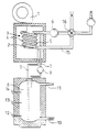
- the drawing shows in a single figure the schematic structure of a heating system according to the invention for space heating and domestic water heating, the illustration being limited to the essential components.
- the system parts for space heating are not shown.
- An over-stoichiometric premixing gas burner 1 with a cylindrical flame holder 2 serves as the heat generator for the heating system.
- the output of the gas burner 1 can be regulated in a modulating manner.
- the gas burner 1 is surrounded by a coaxial tube 3. This is formed by a heating heat exchanger 4 and a domestic hot water heat exchanger 5 arranged therein.
- the coaxial tube 3 is spiral-shaped and is arranged at a distance around the cylindrical flame holder 2 of the gas burner 1. The resulting exhaust gas condensate is collected and discharged via a device (not shown) arranged below the coaxial tube 3.
- the heating water to be heated flows in the coaxial tube 3 through an annular space which is formed by the outside of the process water heat exchanger 5 and by the inside of the heating heat exchanger 4.
- the heating water is circulated by means of a pump 6 arranged on the return side in the heating water circuit 15.
- the process water flows through the process water heat exchanger 5 and is connected via pipes 7 to a stratified storage tank 8 which works on the displacement principle.
- a stratified storage tank 8 which works on the displacement principle.
- cold water is removed from its lower part and fed to the process water heat exchanger 5.
- the process water is heated and then returned to the stratified storage tank 8 by being led into the upper part of the container.
- the process water is circulated by means of a charging pump 9, the direction of which can be reversed depending on the state of charge of the store 8 and the heating requirements.
- the stratified storage tank 8 has a cold water supply 10 in the lower part and a removal point 11 for the hot water intended for consumption in the upper part.
- the water temperature is measured at three points in the stratified storage tank 8.
- the respective charge state of the stratified storage device 8 can be determined by means of the three temperature sensors 12, 13, 14.
- a mixing device 16 is arranged, which can be regulated in dependence on the heating and / or on the hot water requirement in such a way that the heating water circuit 15 on the mixing device 16 can be closed.
- the gas burner 1, the mixing device 16 and the charge pump 9 and the circulation pump 6 are controlled by means of the control device customary for such heating systems.
- heating system could be combined with a controlled home ventilation system, so that a comprehensive heat recovery is possible.
- the heating water circuit can be used to supply an indirectly heated warm air generator.
Abstract
Description
Die Erfindung bezieht sich auf ein Beheizungssystem zur kombinierten Wärmeerzeugung für eine Heizungsanlage und einen Speicherbehälter für Brauchwasser mit einem Brenner für flüssige und gasförmige Brennstoffe, einen in dessen Abgasweg angeordneten vom Heizungswasser durchströmten Heizungswärmetauscher, einem Heizungswasserkreislauf, in dem eine Mischeinrichtung angeordnet ist, und einem Brauchwasserwärmetauscher zur Erwärmung des Brauchwassers.The invention relates to a heating system for combined heat generation for a heating system and a storage tank for process water with a burner for liquid and gaseous fuels, a heating heat exchanger through which the heating water flows, a heating water circuit in which a mixing device is arranged, and a process water heat exchanger for heating the domestic water.
Beheizungssysteme dieser Art sind allgemein bekannt (siehe z.B. die DE-A-4 007 439) und dienen neben der Beheizung von Wohnungen und Gebäuden der indirekten Brauchwassererwärmung in einem Speicherbehälter. Bei Systemen der bekannten Art ist üblicherweise im Abgasstrom eines Brenners ein von Heizungswasser durchströmter Wärmetauscher angeordnet. Das Heizungswasser dient zur Raumbeheizung sowie zur indirekten Brauchwassererwärmung mittels eines im Speicherbehälter angeordneten Wärmetauschers. Eine im Heizungswasserkreislauf angeordnete Mischeinrichtung ist mit einer für derartige Beheizungssysteme üblichen Regeleinrichtung verbunden. Die Mischeinrichtung dient zur Verteilung des erwärmten Heizungswassers zur Heizungsanlage und zum Wärmetauscher des Speicherbehälters. Die Brauchwassererwärmung erfolgt in der Regel mit Hilfe einer Vorrangschaltung.Heating systems of this type are generally known (see, for example, DE-A-4 007 439) and, in addition to heating apartments and buildings, are used for indirect hot water heating in a storage tank. In systems of the known type, a heat exchanger through which heating water flows is usually arranged in the exhaust gas stream of a burner. The heating water is used for space heating and for indirect hot water heating by means of a heat exchanger arranged in the storage tank. A mixing device arranged in the heating water circuit is connected to a control device customary for such heating systems. The mixing device is used to distribute the heated heating water to the heating system and to the heat exchanger of the storage tank. Domestic water is usually heated using a priority switch.
Die bekannten Heizungssysteme haben den Nachteil, daß die Brennerleistung primär zur Deckung des Wärmebedarfes für die Warmwasserbereitung ausgelegt ist und somit häufig deutlich über dem Heizungswärmebedarf liegt. Ein weiterer Nachteil sind die relativ großen Stillstandsverluste bei der Warmwasserbereitung in den Sommermonaten. Des weiteren sorgt ein energiebewußteres Verbraucherverhalten und eine verbesserte Wärmedämmung der Häuser dafür, daß der Heizungsbedarf sinkt, wogegen ein steigender Komfortanspruch den Energiebedarf für die Warmwasserbereitung gegenüber dem Heizungsbedarf prozentual ansteigen läßt. Dies führt bei den bekannten Beheizungssystemen zur Verschlechterung des Gesamtwirkungsgrades und damit zu unnötig hohen Energiekosten.The known heating systems have the disadvantage that the burner output is primarily designed to cover the heat requirement for water heating and is therefore often significantly higher than the heating requirement. Another disadvantage are the relatively large ones Downtime losses in hot water production in the summer months. Furthermore, more energy-conscious consumer behavior and improved thermal insulation of the houses ensure that the heating requirement drops, whereas an increasing demand for comfort increases the energy requirement for water heating compared to the heating requirement as a percentage. In the known heating systems, this leads to a deterioration in the overall efficiency and thus to unnecessarily high energy costs.
Der Erfindung liegt daher die Aufgabe zugrunde, ein Beheizungssystem der gattungsgemäßen Art derart auszubilden, daß die Wärmeübertragungsvorgänge optimiert werden und somit eine Erhöhung der Energieausnutzung erreicht wird, so daß sich der Gesamtwirkungsgrad des Beheizungssystems verbessert.The invention is therefore based on the object of designing a heating system of the generic type in such a way that the heat transfer processes are optimized and thus an increase in energy utilization is achieved, so that the overall efficiency of the heating system is improved.
Ausgehend von dem Beheizungssystem der eingangs genannten Art wird diese Aufgabe gemäß der Erfindung dadurch gelöst, daß der Brauchwasserwärmetauscher innerhalb des Heizungswärmetauschers angeordnet ist und vom Heizungswasser umströmt wird, daß der Heizungswasserkreislauf mittels der Mischeinrichtung trennbar ist, daß der Speicherbehälter als ein nach dem Verdrängungsprinzip arbeitender Schichtenspeicher ausgebildet ist und einen mit einer Ladepumpe versehenen Brauchwasserladekreislauf aufweist.Starting from the heating system of the type mentioned, this object is achieved according to the invention in that the process water heat exchanger is arranged within the heating heat exchanger and the heating water flows around it, that the heating water circuit can be separated by means of the mixing device, that the storage tank acts as a stratified storage tank working according to the displacement principle is formed and has a domestic water charging circuit provided with a charging pump.
Durch ein derartiges Beheizungssystem ist bei der alleinigen Brauchwassererwärmung, beim alleinigen Heizungsbetrieb und im kombinierten Betrieb eine optimale Brennwertnutzung während eines großen Teils des Jahres möglich.Such a heating system enables optimum use of the condensing calorific during a large part of the year for domestic hot water heating, heating operation alone and in combined operation.
Die Anordnung des Brauchwasserwärmetauschers innerhalb des Heizungswärmetauschers bewirkt eine Verbesserung des Wirkungsgrades insbesondere dadurch, daß in allen Betriebsweisen die im Abgas des Brenners enthaltenen Kondensationswärme genutzt werden kann. Ein weiterer Vorteil ist, daß auf zusätzliche Wärmetauscher verzichtet werden kann.The arrangement of the hot water heat exchanger within the heating heat exchanger brings about an improvement in efficiency, in particular in that the condensation heat contained in the exhaust gas of the burner can be used in all operating modes. Another advantage is that there is no need for additional heat exchangers.
Zur Brauchwassererwärmung, die üblicherweise gegenüber dem Heizungsbetrieb vorrangig erfolgt, wird der Heizungswasserkreislauf unterbrochen. Das Brauchwasser sorgt im Wärmetauscher dafür, daß die Temperatur des in einem stark verkleinerten Kreislauf umgewälzten Heizungswassers schnell absinkt. Dieses bewirkt eine niedrige Oberflächentemperatur auf der Außenseite des Wärmetauschers und somit die Kondensation des Wasserdampfes im Abgas. Die Temperatur des Heizungswassers im Ringraum ist dabei während der gesamten Aufheizzeit des Brauchwassers nur etwa 5 bis 10 K höher als die des zu erwärmenden Brauchwassers, das vorzugsweise im Gleichstrom zum Heizungswasser durch den Wärmetauscher strömt.The heating water circuit is interrupted for domestic water heating, which usually takes priority over heating operation. The process water in the heat exchanger ensures that the temperature of the heating water circulated in a greatly reduced circuit quickly drops. This causes a low surface temperature on the outside of the heat exchanger and thus the condensation of the water vapor in the exhaust gas. The temperature of the heating water in the annulus is only about 5 to 10 K higher than that of the hot water to be heated, which preferably flows in direct current to the heating water through the heat exchanger during the entire heating time of the hot water.
Bei der kombinierten Betriebsweise erfolgt die Brauchwassererwärmung zur Befüllung des Schichtenspeichers parallel zum Heizungsbetrieb. Heizungs- und Brauchwasser strömen dabei vorzugsweise im Gleichstrom.In the combined mode of operation, domestic hot water is used to fill the stratified storage tank in parallel with the heating mode. Heating and process water preferably flow in direct current.
Der Speicherbehälter ist als ein nach dem Verdrängungsprinzip arbeitender Schichtenspeicher ausgebildet. Dies ist energetisch besonders vorteilhaft.The storage container is designed as a stratified storage system operating on the displacement principle. This is particularly advantageous in terms of energy.
Die Erfindung ist dadurch weitergebildet, daß der Heizungswärmetauscher mit einem Brauchwasserwärmetauscher ein Koaxialrohr bildet. Dieses bewirkt vorteilhafterweise eine gute Wärmeübertragung zwischen den Wärmetauschern.The invention is further developed in that the heating heat exchanger forms a coaxial tube with a hot water heat exchanger. This advantageously brings about good heat transfer between the heat exchangers.
Erfindungsgemäß ist das Koaxialrohr spiralförmig ausgebildet, so daß es in Verbindung mit einem Brenner mit zylindrischem Flammenhalter eine optimale Wärmeübertragung erreicht wird. Ein weiterer Vorteil ist, daß sich durch eine derartige Form die Strömungswiderstände im Koaxialrohr verringern. Zur optimalen Wärmeübertragung hat sich die Anzahl von 3 bis 4 Windungen als vorteilhaft erwiesen.According to the invention, the coaxial tube is designed in a spiral shape, so that optimum heat transfer is achieved in connection with a burner with a cylindrical flame holder. Another advantage is that such a shape reduces the flow resistances in the coaxial tube. The number of 3 to 4 turns has proven to be advantageous for optimal heat transfer.
Durch die erfindungsgemäße Ausbildung ist das Koaxialrohr um den Brenner gewickelt, wobei dieser einen zylindrischen Flammenhalter aufweist und als überstöchiometrisches vermischender Brenner ausgebildet ist. Die niedrige abgasseitige Oberflächentemperatur des Heizungswärmetauschers ermöglicht eine optimale Kondensation des Wasserdampfes im Abgasstrom des Brenners.As a result of the design according to the invention, the coaxial tube is wound around the burner, which has a cylindrical flame holder and is designed as an over-stoichiometric mixing burner. The low exhaust gas surface temperature of the Heating heat exchanger enables optimal condensation of the water vapor in the exhaust gas flow from the burner.
Bei der Auslegung eines derartigen Beheizungssystems kann sich die Brennerleistung vorteilhafterweise ausschließlich am Heizungswärmebedarf orientieren. Dieses hat den Vorteil, daß man mit Brennern kleinerer Leistung auskommt und gleichzeitig für die Brauchwassererwärmung einen kontinuierlichen Brennerbetrieb ermöglicht. Hierdurch verringern sich insbesondere in den Sommermonaten die Stillstandsverluste.When designing such a heating system, the burner output can advantageously be based exclusively on the heating requirements. This has the advantage that one can get by with burners of lower output and at the same time enables continuous burner operation for domestic water heating. This reduces standstill losses, especially in the summer months.
In Weiterbildung der Erfindung ist die Leistung des Brenners und/oder die Drehzahl der Pumpe regelbar, vorzugsweise im Verhältnis von mindestens 1 : 3. Hierdurch wird eine optimale Anpassung des Brenners an den jeweiligen Heizungswärmebedarf und an die zur Brauchwassererwärmung notwendige Energie erreicht. Dieses bewirkt eine Verringerung von Unterbrechungen im Brennerbetrieb und trägt somit ebenfalls zur Reduzierung von Stillstandsverlusten bei.In a further development of the invention, the output of the burner and / or the speed of the pump can be regulated, preferably in a ratio of at least 1: 3. This achieves an optimal adaptation of the burner to the respective heating requirements and to the energy required to heat the process water. This reduces the number of interruptions in burner operation and thus also helps to reduce downtime losses.
Die Erfindung ist dadurch weitergebildet, daß die Laufrichtung der Ladepumpe in Abhängigkeit vom Ladezustand des Speichers und vom Heizungswärmebedarf umkehrbar ist, so daß Brauchwasser aus dem Schichtenspeicher als Wärmequelle für das Heizungswasser genutzt werden kann. Bei geladenem Schichtenspeicher dient die im unteren Drittel gespeicherte Wärme zur Pufferung der Heizungsanlage, indem warmes Brauchwasser im Gegenstrom zum zu erwärmenden Heizungswasser durch das Koaxialrohr geführt wird. Das Brauchwasser wird dabei aus dem oberen Teil entnommen und in den unteren Teil des Schichtenspeichers zurückgeführt, so daß kein Brennerbetrieb notwendig ist.The invention is further developed in that the running direction of the charge pump is reversible depending on the state of charge of the storage and the heating requirement, so that service water from the stratified storage can be used as a heat source for the heating water. When the stratified storage tank is loaded, the heat stored in the lower third is used to buffer the heating system by passing hot domestic water through the coaxial pipe in counterflow to the heating water to be heated. The process water is removed from the upper part and returned to the lower part of the stratified storage tank, so that no burner operation is necessary.
Durch eine derartige Schaltung wird der kurzzeitige Brennerbetrieb vermieden, so daß längere ununterbrochene Stillstandszeiten entstehen und sich somit die Wärmeverluste weiter verringern lassen.With such a circuit, the short-time burner operation is avoided, so that longer uninterrupted downtimes occur and thus the heat losses can be reduced further.
Erfindungsgemäß sind im Schichtenspeicher drei Temperaturfühler angeordnet. Diese dienen zur Bestimmung des Ladezustandes des Schichtenspeichers, der sich dadurch vorteilhafterweise in folgende Ladezustände unterteilen läßt:
- Speicher in ungeladenem Zustand
- Basisvorrat vorhanden
- Komfortbereich erreicht
- Speicher vollständig geladen.
- Storage in an uncharged state
- Basic stock available
- Comfort zone reached
- Memory fully loaded.
Unter Basisvorrat wird verstanden, daß das obere Drittel des Schichtenspeichers mit auf Solltemperatur erwärmtes Bauchwasser gefüllt ist. Der Komfortbereich ist erreicht, wenn die oberen zwei Drittel des Schichtenspeichers mit auf Solltemperatur erwärmtes Brauchwasser gefüllt sind. Bei vollständig geladenem Schichtenspeicher kann, wie bereits erläutert, die im unteren Drittel gespeicherte Wärme zur Pufferung der Heizungsanlage genutzt werden.The basic stock is understood to mean that the upper third of the stratified storage tank is filled with belly water heated to the desired temperature. The comfort range is reached when the top two thirds of the stratified storage tank are filled with hot water heated to the target temperature. When the stratified storage tank is fully charged, as already explained, the heat stored in the lower third can be used to buffer the heating system.
Durch die erfindungsgemäße außenseitige Berippung oder Profilierung des Heizungswärmetauschers wird dessen Oberfläche derart vergrößert, daß ein optimaler Wärmeaustausch zwischen dem Abgas des Brenners und dem durch den Heizungswärmetauscher strömenden Heizungswasser stattfindet.Due to the external ribbing or profiling of the heating heat exchanger according to the invention, its surface area is increased in such a way that an optimal heat exchange takes place between the exhaust gas of the burner and the heating water flowing through the heating heat exchanger.
In Weiterbildung der Erfindung ist auch der im Heizungswärmetauscher angeordnete Brauchwasserwarmetauscher mit Rippen- oder Profilelementen versehen, wobei diese eine wärmeübertragende Verbindung mit dem Heizungswärmetauscher bilden können. Diese Elemente dienen zur Verbesserung des Wärmeübergangs zwischen Heizungswasser und Brauchwasser.In a further development of the invention, the domestic water heat exchanger arranged in the heating heat exchanger is also provided with ribs or profile elements, which can form a heat-transferring connection with the heating heat exchanger. These elements serve to improve the heat transfer between heating water and process water.
Zur weiteren Verbesserung der Wärmeübertragung wird das Heizungswasser erfindungsgemäß im Gegenstrom zum Brauchwasser durch das Koaxialrohr geführt.To further improve the heat transfer, the heating water is led according to the invention in countercurrent to the process water through the coaxial pipe.
Die erfindungsgemäße Ausbildung des Braucherwasserwärmetauschers aus Kupfer oder Edelstahl und des Heizungswärmetauschers aus Aluminium bewirken aufgrund hoher Wärmedurchgangsquotienten eine gute Wärmeleitung zwischen Brauch- und Heizungswasser sowie zwischen Heizungswasser und Abgas. Zur Vermeidung von Korrossionsschäden wird der Heizungswärmetauscher mit einer korrosionsbeständigen Beschichtung versehen. Das Koaxialrohr läßt sich relativ einfach und kostengünstig herstellen.The inventive design of the hot water heat exchanger made of copper or stainless steel and the heating heat exchanger made of aluminum cause good heat conduction between hot water and heating water and between due to high heat transfer quotients Heating water and exhaust gas. To avoid corrosion damage, the heating heat exchanger is provided with a corrosion-resistant coating. The coaxial tube can be produced relatively easily and inexpensively.
Als Erfindungswesentlich offenbart gelten auch solche Kombinationen der erfindungsgemäßen Merkmale, die von den oben diskutierten Verknüpfungen abweichen.Combinations of the features according to the invention which differ from the links discussed above are also considered to be essential to the invention.
Die Erfindung wird im folgenden anhand eines bevorzugten Ausführungsbeispiels im Zusammenhang mit einer beiliegenden Zeichnung näher erläutert. Die Zeichnung zeigt in einer einzigen Figur, den schematischen Aufbau eines erfindungsgemäßen Beheizungssystems für die Raumbeheizung und Brauchwassererwärmung, wobei sich die Darstellung auf die wesentlichen Komponenten beschränkt. Die Anlagenteile zur Raumbeheizung sind nicht dargestellt.The invention is explained below with reference to a preferred embodiment in connection with an accompanying drawing. The drawing shows in a single figure the schematic structure of a heating system according to the invention for space heating and domestic water heating, the illustration being limited to the essential components. The system parts for space heating are not shown.
Als Wärmeerzeuger für das Beheizungssystem dient ein überstöchiometrisch vormischender Gasbrenner 1 mit einem zylinderförmigen Flammenhalter 2. Der Gasbrenner 1 ist in seiner Leistung modulierend regelbar.An over-stoichiometric premixing gas burner 1 with a
Der Gasbrenner 1 ist von einem Koaxialrohr 3 umgeben. Dieses wird von einem Heizungswärmetauscher 4 und einem darin angeordneten Brauchwasserwärmetauscher 5 gebildet. Das Koaxialrohr 3 ist spiralförmig ausgebildet und mit Abstand um den zylindrischen Flammenhalter 2 des Gasbrenners 1 angeordnet. Das anfallende Abgaskondensat wird über eine unterhalb des Koaxialrohres 3 angeordnete nicht dargestellte Einrichtung gesammelt und abgeführt.The gas burner 1 is surrounded by a
Das zu erwärmende Heizungswasser strömt im Koaxialrohr 3 durch einen Ringraum, der von der Außenseite des Brauchwasserwärmetauschers 5 und von der Innenseite des Heizungswärmetauschers 4 gebildet wird. Das Heizungswasser wird mittels einer rücklaufseitig im Heizwasserkreislauf 15 angeordneten Pumpe 6 umgewälzt.The heating water to be heated flows in the
Der Brauchwasserwärmetauscher 5 wird von Brauchwasser durchströmt und ist über Rohrleitungen 7 mit einem nach dem Verdrängungsprinzip arbeitenden Schichtenspeicher 8 verbunden. Zum Laden des Schichtenspeichers 8 wird aus dessen unterem Teil kaltes Wasser entnommen und dem Brauchwasserwärmetauscher 5 zugeführt. Dort wird das Brauchwasser erwärmt und anschließend zum Schichtenspeicher 8 zurückgeführt, indem es in den oberen Teil des Behälters geleitet wird. Das Brauchwasser wird dabei mittels einer Ladepumpe 9 umgewälzt, deren Laufrichtung in Abhängigkeit vom Ladezustand des Speichers 8 und vom Heizungswärmebedarf umkehrbar ist.The process water flows through the process
Des weiteren weist der Schichtenspeicher 8 im unteren Teil eine Kaltwasserzuführung 10 und im oberen Teil eine Entnahmestelle 11 für das zum Verbrauch bestimmte Warmwasser auf.Furthermore, the
Im Schichtenspeicher 8 wird die Wassertemperatur an drei Stellen gemessen. Hierzu dienen ein im unteren Teil angeordneter erster Temperaturfühler 12, ein im mittleren Teil angeordneter zweiter Temperaturfühler 13 und ein im oberen Teil angeordneter dritter Temperaturfühler 14, die mit einer nicht dargestellten Regeleinrichtung verbunden sind. Mittels der drei Temperaturfühler 12, 13, 14 läßt sich der jeweilige Ladezustand des Schichtenspeichers 8 bestimmen.The water temperature is measured at three points in the
Im Heizungswasserkreislauf 15 ist eine Mischeinrichtung 16 angeordnet, die in Abhängigkeit vom Heizungswärme- und/oder vom Brauchwasserbedarf derart regelbar ist, daß der Heizungswasserkreislauf 15 an der Mischeinrichtung 16 schließbar ist.In the
Der Gasbrenner 1, die Mischeinrichtung 16 sowie die Ladepumpe 9 und die Umwälzpumpe 6 werden mittels der für derartige Beheizungssysteme üblichen Regeleinrichtung geregelt.The gas burner 1, the mixing
Im Rahmen der Erfindung sind ohne weiteres Abwandlungsmöglichkeiten gegeben. Beispielsweise könnte ein derartiges Beheizungssystem mit einem kontrollierten Wohnungsbelüftungssystem kombiniert werden, so daß eine umfassende Wärmerückgewinnung möglich ist. In Kombination mit einer Warmluftheizung kann der Heizungswasserkreislauf dazu benutzt werden, einen indirekt beheizten Warmlufterzeuger zu versorgen.Within the scope of the invention, modification options are readily available. For example, such a heating system could be combined with a controlled home ventilation system, so that a comprehensive heat recovery is possible. In combination with warm air heating, the heating water circuit can be used to supply an indirectly heated warm air generator.
Claims (10)
- A heating system for combined heat production for a heating installation and a storage vessel (8) for domestic water comprising- a burner (1) for liquid or gaseous fuels,- a heat exchanger for the heating system (4) arranged in the flue gas conduit of said burner and through which the system water flows,- a system water circuit (15) in which a mixing device (16) is disposed,- and a domestic water heat exchanger (5) for heating the domestic water,characterised in that the domestic water heat exchanger (5) is arranged inside the heat exchanger (4) of the heating system and the system water is circulated around said domestic water heat exchanger (5), that the system water circuit (15) can be isolated by means of the mixing device (16), that the storage vessel (8) is designed as a stratified storage vessel (8) operating according to the displacement principle and features a domestic water feed circuit provided with a feed pump (9).
- A heating system according to claim 1, characterised in that the heat exchanger (4) of the heating system forms a coaxial tube (3) with the domestic water heat exchanger (5).
- A heating system according to claim 2, characterised in that the coaxial tube (3) is spiral in shape.
- A heating system according to at least one of claims 2 through 3, characterised in that the coaxial tube (3) is wound around the burner (1), said burner featuring a mixer for premixing a fuel-lean mixture and a cylindrical perforated flame-retaining device (2).
- A heating system according to at least one of claims 1 through 4, characterised in that the rating of the burner (1) and/or the feed pump (9) can be controlled, preferably with a ratio of at least 1 : 3.
- A heating system according to at least one of claims 1 though 5, characterised in that the direction of rotation of the feed pump (9) can be reversed depending on the feed requirements of the stratified storage vessel (8) and the space heating requirements so that domestic water from the stratified storage vessel (8) serves as a source of heat for the water of the heating system.
- A heating system according to at least one of claims 1 through 6, characterised in that a first temperature sensor (12) measures the water temperature in the bottom section of the stratified storage vessel (8) and a second temperature sensor (13) measures the water temperature in the middle section and a third temperature sensor (14) measuring the water temperature in the top section serves to control the burner (1), the mixing device (16) andlor the feed pump (9).
- A heating system according to at least one of claims 1 through 7, characterised in that the heat exchanger (4) of the heating system has ribs on its exterior and is profiled.
- A heating system according to at least one of claims 1 through 8, characterised in that the domestic water heat exchanger (5) is ribbed and profiled.
- A heating system according to at least one of claims 1 through 9, characterised in that the heat exchanger (4) of the heating system is made of aluminium, preferably with a corrosion-resistant coating and that the domestic water heat exchanger (5) is made preferably of copper or special steel.
Applications Claiming Priority (2)
| Application Number | Priority Date | Filing Date | Title |
|---|---|---|---|
| DE4142488A DE4142488A1 (en) | 1991-12-20 | 1991-12-20 | HEATING SYSTEM FOR COMBINED HEAT GENERATION AND A HEATING SYSTEM AND A STORAGE TANK FOR DOMESTIC WATER |
| DE4142488 | 1991-12-20 |
Publications (2)
| Publication Number | Publication Date |
|---|---|
| EP0548719A1 EP0548719A1 (en) | 1993-06-30 |
| EP0548719B1 true EP0548719B1 (en) | 1995-01-18 |
Family
ID=6447821
Family Applications (1)
| Application Number | Title | Priority Date | Filing Date |
|---|---|---|---|
| EP92121213A Revoked EP0548719B1 (en) | 1991-12-20 | 1992-12-12 | Heating system for combined heat production for a heating installation and a storage vessel for domestic water |
Country Status (3)
| Country | Link |
|---|---|
| EP (1) | EP0548719B1 (en) |
| AT (1) | ATE117423T1 (en) |
| DE (2) | DE4142488A1 (en) |
Families Citing this family (5)
| Publication number | Priority date | Publication date | Assignee | Title |
|---|---|---|---|---|
| DE4407457A1 (en) * | 1994-03-05 | 1995-09-07 | Broetje August Gmbh & Co | Operation of heating plant with storage tank |
| DE102005019856B4 (en) * | 2005-04-28 | 2009-08-20 | Sun-Systems Gmbh | Continuous heater for a useful fluid and hydraulic circuit |
| PL1892480T3 (en) * | 2006-08-22 | 2011-05-31 | Sun Systems Gmbh | Continuous flow-heater for fluid, use of said continuos-flow heater and method of heating a workfluid in such a hydraulic circuit |
| GB2450414B (en) * | 2007-06-19 | 2012-06-20 | Ravenheat Mfg Ltd | Improvements in and relating to water heating |
| GB201610729D0 (en) * | 2016-06-20 | 2016-08-03 | Evans Peter And Sallaku Arben | Boiler |
Family Cites Families (9)
| Publication number | Priority date | Publication date | Assignee | Title |
|---|---|---|---|---|
| DE1753433B1 (en) * | 1961-03-27 | 1970-08-06 | Buderus Eisenwerk | Device for heating liquids, especially water |
| DE2142545B1 (en) * | 1971-08-25 | 1973-02-08 | Joh. Vaillant Kg, 5630 Remscheid | |
| US3999709A (en) * | 1975-05-05 | 1976-12-28 | Estabrook Paul S | Water heater |
| DE8111726U1 (en) * | 1981-04-18 | 1982-02-04 | Kempf, Lothar, 5239 Unnau | BUFFER STORAGE FOR A PLANT FOR HEATING BUILDINGS AND HEATING HOT WATER |
| FR2550615B1 (en) * | 1983-08-12 | 1985-12-06 | Fonderie Soc Gen De | SERPENTINE EXCHANGER BOILER |
| DE8530184U1 (en) * | 1985-10-22 | 1986-05-07 | Joh. Vaillant Gmbh U. Co, 5630 Remscheid | Water heater |
| DE3714261C1 (en) * | 1987-04-29 | 1988-07-07 | Rolf Bommer | Condensing boiler and method for its operation |
| GB2228563A (en) * | 1989-02-28 | 1990-08-29 | Michael John Nunnerley | Heat exchange system |
| DE4007439A1 (en) * | 1990-03-09 | 1991-09-12 | B E C Henning Becker Gmbh | Sterilising hot water tank contents by regulated overheating - with auxiliary heat exchanger submerged in tank |
-
1991
- 1991-12-20 DE DE4142488A patent/DE4142488A1/en not_active Withdrawn
-
1992
- 1992-12-12 DE DE59201234T patent/DE59201234D1/en not_active Revoked
- 1992-12-12 AT AT92121213T patent/ATE117423T1/en not_active IP Right Cessation
- 1992-12-12 EP EP92121213A patent/EP0548719B1/en not_active Revoked
Also Published As
| Publication number | Publication date |
|---|---|
| DE4142488A1 (en) | 1993-07-01 |
| DE59201234D1 (en) | 1995-03-02 |
| ATE117423T1 (en) | 1995-02-15 |
| EP0548719A1 (en) | 1993-06-30 |
Similar Documents
| Publication | Publication Date | Title |
|---|---|---|
| DE2925793C2 (en) | ||
| EP0001419B1 (en) | Installation with a heat pump for central heating and for domestic water heating | |
| AT508481B1 (en) | METHOD FOR HEATING HOT WATER | |
| EP0288695B1 (en) | Condensing boiler and method for its operation | |
| EP0561032B1 (en) | Heat accumulator as storage buffer for room heating | |
| EP1058803B1 (en) | Heat accumulator | |
| EP0548719B1 (en) | Heating system for combined heat production for a heating installation and a storage vessel for domestic water | |
| DE19707184A1 (en) | Hot water storage tank | |
| EP0795109B1 (en) | Water heater | |
| DE2803649A1 (en) | HEATING SYSTEM | |
| DE2929810A1 (en) | DEVICE FOR HEAT RECOVERY FROM EXHAUST GAS AND HEAT EXCHANGE ELEMENT HERE | |
| DE19815521A1 (en) | Heat recovery system for building heating | |
| DE202009018196U1 (en) | Highly efficient, solar-assisted condensing gas storage heater for liquid or gaseous fuels for generating domestic hot water and heating heat for space heating | |
| EP0699878B1 (en) | High efficiency boiler for heating and storing domestic water and heating water | |
| DE20317011U1 (en) | Hot water tank used in the production of domestic hot water using solar collectors comprises a counter-current heat exchanger arranged within the storage tank and containing hot water | |
| EP1178269B1 (en) | Sorption heat pump | |
| DE3308447C2 (en) | Device for generating hot water | |
| DE4116375C2 (en) | ||
| AT507569B1 (en) | METHOD FOR HEATING HOT WATER | |
| EP1724415A2 (en) | Controlled two zone accumulator for fresh sanitary water heating | |
| WO2002012814A1 (en) | Latent heat storage device | |
| DE3152206A1 (en) | A cistern arrangement for heating tap water | |
| AT501612B1 (en) | METHOD FOR OPERATING A HOT WATER TREATMENT PLANT AND HOT WATER TREATMENT PLANT | |
| EP0238776B1 (en) | Method of running a heating installation and heat accumulator for this heating installation | |
| DE4438108A1 (en) | Auxiliary heating of domestic water |
Legal Events
| Date | Code | Title | Description |
|---|---|---|---|
| PUAI | Public reference made under article 153(3) epc to a published international application that has entered the european phase |
Free format text: ORIGINAL CODE: 0009012 |
|
| AK | Designated contracting states |
Kind code of ref document: A1 Designated state(s): AT BE CH DE DK FR GB IT LI NL |
|
| 17P | Request for examination filed |
Effective date: 19930915 |
|
| 17Q | First examination report despatched |
Effective date: 19940622 |
|
| GRAA | (expected) grant |
Free format text: ORIGINAL CODE: 0009210 |
|
| AK | Designated contracting states |
Kind code of ref document: B1 Designated state(s): AT BE CH DE DK FR GB IT LI NL |
|
| PG25 | Lapsed in a contracting state [announced via postgrant information from national office to epo] |
Ref country code: IT Free format text: LAPSE BECAUSE OF FAILURE TO SUBMIT A TRANSLATION OF THE DESCRIPTION OR TO PAY THE FEE WITHIN THE PRE;WARNING: LAPSES OF ITALIAN PATENTS WITH EFFECTIVE DATE BEFORE 2007 MAY HAVE OCCURRED AT ANY TIME BEFORE 2007. THE CORRECT EFFECTIVE DATE MAY BE DIFFERENT FROM THE ONE RECORDED.SCRIBED TIME-LIMIT Effective date: 19950118 Ref country code: DK Effective date: 19950118 Ref country code: FR Effective date: 19950118 Ref country code: GB Effective date: 19950118 Ref country code: BE Effective date: 19950118 |
|
| REF | Corresponds to: |
Ref document number: 117423 Country of ref document: AT Date of ref document: 19950215 Kind code of ref document: T |
|
| REF | Corresponds to: |
Ref document number: 59201234 Country of ref document: DE Date of ref document: 19950302 |
|
| EN | Fr: translation not filed | ||
| GBV | Gb: ep patent (uk) treated as always having been void in accordance with gb section 77(7)/1977 [no translation filed] |
Effective date: 19950118 |
|
| PLBI | Opposition filed |
Free format text: ORIGINAL CODE: 0009260 |
|
| PGFP | Annual fee paid to national office [announced via postgrant information from national office to epo] |
Ref country code: DE Payment date: 19951116 Year of fee payment: 4 |
|
| PGFP | Annual fee paid to national office [announced via postgrant information from national office to epo] |
Ref country code: NL Payment date: 19951122 Year of fee payment: 4 |
|
| PG25 | Lapsed in a contracting state [announced via postgrant information from national office to epo] |
Ref country code: AT Effective date: 19951212 |
|
| 26 | Opposition filed |
Opponent name: ROBERT BOSCH GMBH Effective date: 19951018 |
|
| PG25 | Lapsed in a contracting state [announced via postgrant information from national office to epo] |
Ref country code: CH Free format text: LAPSE BECAUSE OF NON-PAYMENT OF DUE FEES Effective date: 19951231 Ref country code: LI Free format text: LAPSE BECAUSE OF NON-PAYMENT OF DUE FEES Effective date: 19951231 |
|
| NLR1 | Nl: opposition has been filed with the epo |
Opponent name: ROBERT BOSCH GMBH |
|
| PLBF | Reply of patent proprietor to notice(s) of opposition |
Free format text: ORIGINAL CODE: EPIDOS OBSO |
|
| PLBF | Reply of patent proprietor to notice(s) of opposition |
Free format text: ORIGINAL CODE: EPIDOS OBSO |
|
| REG | Reference to a national code |
Ref country code: CH Ref legal event code: PL |
|
| RDAH | Patent revoked |
Free format text: ORIGINAL CODE: EPIDOS REVO |
|
| RDAG | Patent revoked |
Free format text: ORIGINAL CODE: 0009271 |
|
| STAA | Information on the status of an ep patent application or granted ep patent |
Free format text: STATUS: PATENT REVOKED |
|
| 27W | Patent revoked |
Effective date: 19970303 |
|
| NLV4 | Nl: lapsed or anulled due to non-payment of the annual fee |
Effective date: 19970701 |