EP0548219B1 - Lining - Google Patents
Lining Download PDFInfo
- Publication number
- EP0548219B1 EP0548219B1 EP91916831A EP91916831A EP0548219B1 EP 0548219 B1 EP0548219 B1 EP 0548219B1 EP 91916831 A EP91916831 A EP 91916831A EP 91916831 A EP91916831 A EP 91916831A EP 0548219 B1 EP0548219 B1 EP 0548219B1
- Authority
- EP
- European Patent Office
- Prior art keywords
- lining
- casing
- ceramic
- supports
- materials
- Prior art date
- Legal status (The legal status is an assumption and is not a legal conclusion. Google has not performed a legal analysis and makes no representation as to the accuracy of the status listed.)
- Expired - Lifetime
Links
Images

Classifications
-
- B—PERFORMING OPERATIONS; TRANSPORTING
- B04—CENTRIFUGAL APPARATUS OR MACHINES FOR CARRYING-OUT PHYSICAL OR CHEMICAL PROCESSES
- B04C—APPARATUS USING FREE VORTEX FLOW, e.g. CYCLONES
- B04C5/00—Apparatus in which the axial direction of the vortex is reversed
- B04C5/08—Vortex chamber constructions
- B04C5/085—Vortex chamber constructions with wear-resisting arrangements
-
- B—PERFORMING OPERATIONS; TRANSPORTING
- B04—CENTRIFUGAL APPARATUS OR MACHINES FOR CARRYING-OUT PHYSICAL OR CHEMICAL PROCESSES
- B04C—APPARATUS USING FREE VORTEX FLOW, e.g. CYCLONES
- B04C5/00—Apparatus in which the axial direction of the vortex is reversed
- B04C5/08—Vortex chamber constructions
-
- B—PERFORMING OPERATIONS; TRANSPORTING
- B04—CENTRIFUGAL APPARATUS OR MACHINES FOR CARRYING-OUT PHYSICAL OR CHEMICAL PROCESSES
- B04C—APPARATUS USING FREE VORTEX FLOW, e.g. CYCLONES
- B04C5/00—Apparatus in which the axial direction of the vortex is reversed
- B04C5/08—Vortex chamber constructions
- B04C5/081—Shapes or dimensions
-
- F—MECHANICAL ENGINEERING; LIGHTING; HEATING; WEAPONS; BLASTING
- F27—FURNACES; KILNS; OVENS; RETORTS
- F27D—DETAILS OR ACCESSORIES OF FURNACES, KILNS, OVENS OR RETORTS, IN SO FAR AS THEY ARE OF KINDS OCCURRING IN MORE THAN ONE KIND OF FURNACE
- F27D1/00—Casings; Linings; Walls; Roofs
- F27D1/04—Casings; Linings; Walls; Roofs characterised by the form, e.g. shape of the bricks or blocks used
- F27D1/045—Bricks for lining cylindrical bodies, e.g. skids, tubes
-
- F—MECHANICAL ENGINEERING; LIGHTING; HEATING; WEAPONS; BLASTING
- F27—FURNACES; KILNS; OVENS; RETORTS
- F27D—DETAILS OR ACCESSORIES OF FURNACES, KILNS, OVENS OR RETORTS, IN SO FAR AS THEY ARE OF KINDS OCCURRING IN MORE THAN ONE KIND OF FURNACE
- F27D1/00—Casings; Linings; Walls; Roofs
- F27D1/14—Supports for linings
- F27D1/145—Assembling elements
-
- Y—GENERAL TAGGING OF NEW TECHNOLOGICAL DEVELOPMENTS; GENERAL TAGGING OF CROSS-SECTIONAL TECHNOLOGIES SPANNING OVER SEVERAL SECTIONS OF THE IPC; TECHNICAL SUBJECTS COVERED BY FORMER USPC CROSS-REFERENCE ART COLLECTIONS [XRACs] AND DIGESTS
- Y10—TECHNICAL SUBJECTS COVERED BY FORMER USPC
- Y10T—TECHNICAL SUBJECTS COVERED BY FORMER US CLASSIFICATION
- Y10T428/00—Stock material or miscellaneous articles
- Y10T428/13—Hollow or container type article [e.g., tube, vase, etc.]
- Y10T428/131—Glass, ceramic, or sintered, fused, fired, or calcined metal oxide or metal carbide containing [e.g., porcelain, brick, cement, etc.]
-
- Y—GENERAL TAGGING OF NEW TECHNOLOGICAL DEVELOPMENTS; GENERAL TAGGING OF CROSS-SECTIONAL TECHNOLOGIES SPANNING OVER SEVERAL SECTIONS OF THE IPC; TECHNICAL SUBJECTS COVERED BY FORMER USPC CROSS-REFERENCE ART COLLECTIONS [XRACs] AND DIGESTS
- Y10—TECHNICAL SUBJECTS COVERED BY FORMER USPC
- Y10T—TECHNICAL SUBJECTS COVERED BY FORMER US CLASSIFICATION
- Y10T428/00—Stock material or miscellaneous articles
- Y10T428/13—Hollow or container type article [e.g., tube, vase, etc.]
- Y10T428/131—Glass, ceramic, or sintered, fused, fired, or calcined metal oxide or metal carbide containing [e.g., porcelain, brick, cement, etc.]
- Y10T428/1314—Contains fabric, fiber particle, or filament made of glass, ceramic, or sintered, fused, fired, or calcined metal oxide, or metal carbide or other inorganic compound [e.g., fiber glass, mineral fiber, sand, etc.]
-
- Y—GENERAL TAGGING OF NEW TECHNOLOGICAL DEVELOPMENTS; GENERAL TAGGING OF CROSS-SECTIONAL TECHNOLOGIES SPANNING OVER SEVERAL SECTIONS OF THE IPC; TECHNICAL SUBJECTS COVERED BY FORMER USPC CROSS-REFERENCE ART COLLECTIONS [XRACs] AND DIGESTS
- Y10—TECHNICAL SUBJECTS COVERED BY FORMER USPC
- Y10T—TECHNICAL SUBJECTS COVERED BY FORMER US CLASSIFICATION
- Y10T428/00—Stock material or miscellaneous articles
- Y10T428/13—Hollow or container type article [e.g., tube, vase, etc.]
- Y10T428/131—Glass, ceramic, or sintered, fused, fired, or calcined metal oxide or metal carbide containing [e.g., porcelain, brick, cement, etc.]
- Y10T428/1317—Multilayer [continuous layer]
Definitions
- the present invention relates to a lining in which a material with a certain coefficient of linear expansion constitutes lining for another material with a different coefficient of linear expansion.
- the invention aims to solve the problem with the relative linear displacements in connection with cyclic changes in temperature of the respective materials.
- tubes, tanks, nozzles or similar devices which are to withstand, for example, high temperature, variations in temperature, erosion from particles flow, or some other type of degrading influence on the material.
- the present invention is applicable within each technical field in which linings of the above-mentioned kind are desirable.
- known technique involving ceramic lining of tubes exposed to high temperatures and/or erosive particle flows is chosen.
- a vortex of, for example, flue gases moves from a higher to a lower level inside a cyclone wall with a downwardly tapering circular cross section.
- the speed of the gas flow increases, causing heavier particles present in the gas vortex to be thrown out against the cyclone wall and then to fall down into cyclone legs which form dust outlets from the cyclone.
- the cleaned gas is discharged at the upper part.
- the highest possible gas temperature is desired at the inlet of the turbine. This means that gas cleaners which separate dust from combustion gases operate at the temperature of the combustion gases when these leave a bed in a combustion plant.
- a combustion plant of, for example, PFBC type operates with a gas temperature which may amount to 950°C.
- This high temperature entails heavy stresses in the cyclones for cleaning of the combustion gases before these are supplied to a turbine.
- the problems are particularly great in the lowermost part of the cyclone and in the cyclone legs.
- the high speed of the greatly abrasive, erosive particles in the gas mass and the high temperature reduce the strength of the cyclone material and deteriorate its resistance to wear.
- cyclones Despite different forms of cooling of cyclones and different designs of cyclones and cyclone legs, the problem with the heavy wear on the cyclone material from dust in the gas remains. This has made it necessary to provide cyclones with an erosion-resistant material, usually in the form of a lining.
- This lining may be formed from ceramic material, which has long been known in the art. In already existing PFBC energy plants, the cyclones have been internally lined with a high-resistant ceramic material.
- One way of providing cyclones or other corresponding devices with a ceramically resistant material is to apply a steel net with hexagonal meshes to the surface which is to be coated.
- the net is spot welded to this surface.
- the net has a certain thickness, since the net is formed from steel bands. Inside each mesh there are central holes in the steel band.
- the meshes in the steel net are filled with a ceramic material, usually aluminium oxide, which is fixed in position by the ceramic material penetrating also the holes in the steel band.
- the ceramic gives the surface good resistance to erosion and provides good protection against fires which may arise under certain conditions. In addition, the ceramic withstands temporary increases in temperature.
- cyclones Upon start-up, cyclones are heated from room temperature to operating temperature for a relatively long time. When the ceramic gradually reaches the operating temperature, the temperature of the cyclone wall has risen to about 850°C or around 350°C depending on whether insulation has been applied outside the cyclone wall or between the ceramic and the steel wall.
- Ceramic plates are provided with cast-in steel holders. These holders are welded to the steel casing such that a certain gap arises between the steel casing and the ceramic. The space formed by this gap is filled with insulation. In this way, the ceramic and the steel casing may be arranged to be maintained at different temperatures.
- the two sides of the ceramic assume, for example, the temperature 850°C whereas the steel casing is allowed a maximum temperature of, for example, 350°C.
- a specification of requirements may be drawn up for a lining, the aim of which is to reach a solution to the problems described above. It is, for example, desirable to have large, smooth, continuous surfaces while avoiding joints in the ceramic lining. Another desire is to have as few contact points as possible between the lining and the casing. In addition, it is advantageous to provide a gap between the lining and the casing. In this way, in the example using cyclones, a small amount of gas may sweep over the back of the lining, causing the back to adopt the same temperature as the front to avoid temperature gradients over the lining material. By means of such a gap, dust penetrating in between the lining and the casing may also be allowed exit out of the gap.
- the invention may be described as a lining of one element which constitutes an outer casing by means of another element which constitues an inner lining for the casing, the materials in the two elements having different coefficients of linear expansion.
- the lining is characterized in that the linear expansion of both materials is adapted to emanate from one single common fixed point and that all contact points between the two elements are positioned on imaginary cones or polygonal pyramids, the tips of the cones or the pyramids coinciding with the fixed point, such that the contact points between the two elements are located on the generatrices of the cone, and under relative linear displacements, caused by temperature changes in any of the elements, the contact points have been given a possibility of free movement along the generatrices through the respective contact point.
- each point of the body moves under linear displacements, caused by temperature fluctuations of the body, along a ray which runs from an optional fixed point inside the body. That is to say, if each point in the body is viewed from this fixed point, it seems as if, for example during thermal expansion of the body, each point belonging to the body moves away rectilinearly outwards from the fixed point. The corresponding situation, of course, applies to a contraction of the body, when the points move inwardly towards the fixed point.
- the displacement of the points of the body in the longitudinal direction is in direct proportion to the distance of the respective point from the fixed point.
- the known physical principles described above may be utilized to solve problems with linings.
- this invention it is possible to form a ceramic lining in one single unit or in large sections, where the lining is made such that all external surfaces, which are to function as supporting points, which in some way are to contact the casing to be lined, are located on the envelope surface of an imaginary cone. This cone then constitutes a limiting surface for these supporting points.
- the interior of the casing is formed, such that this exhibits supporting points for the lining, all of these supporting points also being located on the envelope surface of an imaginary cone.
- the described principle for designing a lining may be applied to all technical fields where thermal movements of materials, which are connected to each other in some way, occur. It may, for example, apply to the lining of tubes with erosion-resistant materials at exposed bends, end stops and the like.
- the invention is not limited to two materials. The same principle may be used even if more than two materials are to coat one another.
- Figure 1 shows a section through a ceramic lining of a steel shell intended to be used in a cyclone for cleaning flue gases.
- the lining is divided into several sections.
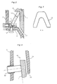
- Figure 2 illustrates a section through a part in the supporting device for the ceramic lining according to Figure 1.
- Figure 3 illustrates a cross section through a supporting yoke according to section A-A in Figure 2.
- Figure 4 shows the embodiment of the connection between the upper part of the lining and the shell.
- a lining of a cyclone leg in a flue gas plant is shown in Figure 1.
- a ceramic lining 1 is enclosed in a steel shell 2.
- the steel shell constitutes a cyclone leg and/or the lower conical part of a cyclone leg. Since it is subjected to high temperature, the steel shell is normally lined around 850°C because of the hot, flowing gas vortex. In addition, the gas in the vortex contains greatly erosive particles. Without a lining, the material in the steel shell would be rapidly worn and deformed.
- the ceramic in the lining may be made in one piece or, as in the preferred embodiment, be made in several sections 1a, 1b, 1c, which are stacked on top of each other.
- Each section 1a, 1b, 1c is made in the form of a tube piece with an internally cylindrical or conical envelope surface. Externally, the respective tube section may be given an optional shape within the scope of the available space and function.
- the end surfaces of the tube sections are given a good planeness, allowing the tube sections to be stacked one above the other and providing good sealing between the joints.
- the tube sections rest freely on one another and each individual tube section is only influenced by forces of gravity from tube sections positioned above, which is the intention of this construction since ceramics has a greater capacity to withstand compressive forces than, for example, tensile forces.
- the length of each section may suitably be in the interval 700 mm to 900 mm but has no other significance than to contribute to a practically manageable solution of the problems of installation and adjustment.
- the ceramic tube sections 1a, 1b, 1c need not be manufactured on the spot and can therefore be made in any optional material. It is fully possible to choose the most erosion-resistant and high-strength materials. As examples of such materials may be mentioned silicon carbide, SiC, or silicon nitride, SiN.
- Each ceramic tube section is externally provided with at least two annular conical sections 3a - 3e, so that the limiting surface of each such conical section forms a frustum of a cone.
- These conical sections are chosen such that all generatrices 4a-4e along the envelope surface of each such frustum of a cone, which forms the conical sections of the tube sections, intersect at one and the same point, called fixed point 5.
- the conical sections are suitably located at the ends of the respective tube sections, with the exception of the tube end where the ceramic lining is supported, where the embodiment of the end of the corresponding tube section will be described separately below. If the ceramic lining is made as one coherent section, an external conical section 3e may, in principle, be sufficient, but the number may be freely chosen according to the circumstances.
- the surrounding steel shell 2 exhibits a number of radial supports 6a-6e.
- these radial supports are arranged in a ring around the steel shell, such a ring of radial supports serving as side supports for the ceramic lining in that each conical section on the lining in principle makes contact with an associated ring of radial supports.
- the radial supports 6a may be angled such that the longitudinal axis 7a through the respective radial support is perpendicular to the nearest generatrix 4a of the associated conical section of the lining, as shown in the figures.
- the lowermost one 1a of the tube sections of the ceramic lining is formed with a collar 8, at a certain distance above the lowermost tube end, with a larger outside diameter than the outside diameter of this tube section below the collar.
- This collar has a substantially horizontal lower surface.
- the steel shell changes into a conical/cylindrical section with a smaller outside diameter.
- a substantially horizontal shelf 9 is formed in the steel shell (see Figure 2).
- On this shelf there rests a circular support ring 10 with an appearance resembling that of a ring-half for a radial bearing.
- the support ring 10 has a surrounding circular and cupped surface 11 directed upwardly and inwardly and towards the centre of the ring.
- a number of supporting elements (hereinafter called flexible supports) 12 are arranged in a ring between the ceramic lining 1 and the steel shell 2.
- Each flexible support 12 rests with its lower end in the cupped surface 11 of the support ring 10 and with its upper end against a rounded part of the ceramic lining which is formed in the angle between the lowermost outer neck of the ceramic lining and the collar 8.
- the flexible supports 12 will carry the weight of the ceramic lining 1 and transfer this weight to the support ring 10 and further to the shelf 9 on the steel shell 2.
- the purpose of the loose flexible supports 12 is to bring about an accurate centering of the ceramic lining 1 in the steel shell 2, so that the symmetry axes for the lining 1 and the steel shell 2 coincide and extend through the above-mentioned fixed point 5. If, for example, the steel shell 2 is expanded to a major extent in relation to the lining 1, the lower supporting legs on the respective flexible supports will be displaced horizontally outwards from the centre, the flexible supports 12 then adopting a somewhat more inwardly sloping position than earlier. In this way, the lining is lowered to some small extent in relation to the steel shell, but the lining is still maintained centered by the uniform influence from all the flexible supports.
- the vertical and horizontal positions of the support ring 10 are adjusted by means of both horizontal adjusting screws 13 through the wall of the steel shell and vertical adjusting screws 14 through the shelf 9.
- the flexible supports 12 are formed as yokes with the yoke legs downwardly rounded and resting in the cupped surface 11.
- the flexible supports are rounded also at the top to conform well to the cupped shape below the collar of the lining.
- the flexible supports 12 are placed close to each other so that each yoke leg on a flexible support in the lateral direction supports against an adjacent flexible support in the ring of such supports.
- the main principle according to the invention is that the two different materials in the ceramic and in the steel casing, respectively, should have one single common point, from where all linear expansion or contraction caused by changes in temperature emanates for the different materials.
- the lining and the steel casing are adapted to include such a point, which is the only point which is common and coinciding under relative temperature displacements between the two materials.
- This point is the same as the above-mentioned fixed point 5.
- the fixed point 5 has been located at the point of intersection between a plane 15 through the lower side of the ceramic collar 8 and the common axis of rotation for the steel shell 2 and the ceramic lining 1.
- the two materials, the steel shell and the lining will be able to move in relation to each other since the conical sections 3a-3e are able to slid along the radial supports 6a-6e along the above-mentioned generatrices 4a-4e, which converge at the fixed point 5.
- This is independent of which of the two materials expands or contracts.
- the lining material will not be subjected to any stresses. This is true provided that the two materials are homogeneous and not influenced by any residual stresses.
- this gap 17 is arranged, through which gas and dust are able to flow out.
- the gas pressure is higher than at the lower part, causing dust to be blown out of the space between the lining and the shell through the lower gap 17.
- the width of this gap 17 may be chosen freely by making the downwardly projecting throat below the collar 8 on the lining longer or shorter.
- the flexible supports 12 have been deliberately designed as yokes, thus forming openings, in this case between the legs of the yokes and between the flexible supports. This allows gas and dust in the gap 16 to traverse the ring of flexible supports and flow out through the lower gap 17.
- a gap 18 is arranged in the upper part of the lining.
- the steel shell 2 can be made with an inner collar which hangs down over the end of the lining as a lip 2a, between which lip and the uppermost lining end the upper gap 18 is formed. Since both the inside of the end of the lining tube and the outside of the overhanging lip 2a towards the lining end are angled in the direction of the fixed point 5, the gap 18 maintains the same width also in case of temperature movements of the two materials. The width of this gap 18 may be freely chosen.
- the ceramic according to the above embodiment it is possible to utilize two separate ceramics in the lining.
- a more inexpensive material with lower erosion resistance but with higher strength in case of a large volume of the body may be used as an external frame in a lining according to the above.
- the inside of the frame is then coated with smaller plates of a different ceramic with the desired properties, such as erosion resistance. Plates with, for example, silicon carbide may then internally coat a frame of aluminium oxide.
Landscapes
- Engineering & Computer Science (AREA)
- Mechanical Engineering (AREA)
- General Engineering & Computer Science (AREA)
- Physics & Mathematics (AREA)
- Geometry (AREA)
- Filtering Of Dispersed Particles In Gases (AREA)
- Laminated Bodies (AREA)
- Cylinder Crankcases Of Internal Combustion Engines (AREA)
- Chimneys And Flues (AREA)
- Cyclones (AREA)
- Crucibles And Fluidized-Bed Furnaces (AREA)
- Furnace Housings, Linings, Walls, And Ceilings (AREA)
- Compositions Of Oxide Ceramics (AREA)
- Physical Or Chemical Processes And Apparatus (AREA)
- Ceramic Products (AREA)
Abstract
Description
- The present invention relates to a lining in which a material with a certain coefficient of linear expansion constitutes lining for another material with a different coefficient of linear expansion. In particular, the invention aims to solve the problem with the relative linear displacements in connection with cyclic changes in temperature of the respective materials.
- In industrial applications there is often a need to line certain elements with a material which exhibits properties quite different from the material from which the element is made. As an example may be mentioned tubes, tanks, nozzles or similar devices which are to withstand, for example, high temperature, variations in temperature, erosion from particles flow, or some other type of degrading influence on the material.
- The present invention is applicable within each technical field in which linings of the above-mentioned kind are desirable. To describe the problems which arise in connection with lining and the solutions that are currently applied, known technique involving ceramic lining of tubes exposed to high temperatures and/or erosive particle flows is chosen.
- In boiler plants, flue gas tubes, cleaning plants for flue gases etc., usually some steel quality is used in walls and casings. If these casings were to be exposed to the influence of very hot flue gases containing erosive particles for a substantial period of time, and under the effect of temperature fluctuations, these casings would be worn out relatively quickly. For this reason, cyclones, for example, which constitute dust cleaning devices in, inter alia, fossil fuelled power plants, are usually provided with a lining, usually of a ceramic material, as described for example in EP-A-0 094 098.
- In a cyclone, a vortex of, for example, flue gases moves from a higher to a lower level inside a cyclone wall with a downwardly tapering circular cross section. During the downward flow, the speed of the gas flow increases, causing heavier particles present in the gas vortex to be thrown out against the cyclone wall and then to fall down into cyclone legs which form dust outlets from the cyclone. The cleaned gas is discharged at the upper part.
- For operation of gas turbines connected to cyclones of the above-mentioned type, the highest possible gas temperature is desired at the inlet of the turbine. This means that gas cleaners which separate dust from combustion gases operate at the temperature of the combustion gases when these leave a bed in a combustion plant.
- A combustion plant of, for example, PFBC type operates with a gas temperature which may amount to 950°C. This high temperature entails heavy stresses in the cyclones for cleaning of the combustion gases before these are supplied to a turbine. The problems are particularly great in the lowermost part of the cyclone and in the cyclone legs. The high speed of the greatly abrasive, erosive particles in the gas mass and the high temperature reduce the strength of the cyclone material and deteriorate its resistance to wear.
- Despite different forms of cooling of cyclones and different designs of cyclones and cyclone legs, the problem with the heavy wear on the cyclone material from dust in the gas remains. This has made it necessary to provide cyclones with an erosion-resistant material, usually in the form of a lining. This lining may be formed from ceramic material, which has long been known in the art. In already existing PFBC energy plants, the cyclones have been internally lined with a high-resistant ceramic material.
- One way of providing cyclones or other corresponding devices with a ceramically resistant material according to known technique is to apply a steel net with hexagonal meshes to the surface which is to be coated. The net is spot welded to this surface. The net has a certain thickness, since the net is formed from steel bands. Inside each mesh there are central holes in the steel band. After application, the meshes in the steel net are filled with a ceramic material, usually aluminium oxide, which is fixed in position by the ceramic material penetrating also the holes in the steel band. The ceramic gives the surface good resistance to erosion and provides good protection against fires which may arise under certain conditions. In addition, the ceramic withstands temporary increases in temperature. One problem, however, are the different coefficients of linear expansion of the ceramic and the lined material.
- Upon start-up, cyclones are heated from room temperature to operating temperature for a relatively long time. When the ceramic gradually reaches the operating temperature, the temperature of the cyclone wall has risen to about 850°C or around 350°C depending on whether insulation has been applied outside the cyclone wall or between the ceramic and the steel wall.
- Prior to start-up of the plant, there are small gaps, at a temperature of about 20°C, between the hexagonal ceramic plates inside the steel meshes and the steel bands of these meshes. During a heating period and because of the greater liner expansion of the steel material, the width of these gaps is increased, dust from the flue gases being packed into these gaps. During the subsequent shrinkage of the materials during an interruption of the operation, or a reduction of the temperatures of the two materials for some other reason, stresses in the ceramic material will arise because of the above-mentioned packing of dust into the gaps, which results in the ceramic being easily broken.
- This problem, of course, is aggravated by repeated increases and falls in temperature.
- Another problem arises with the existing temperature gradient across the inside and outside of the ceramic. Under certain conditions, the temperature difference beween inside and the outside of the ceramic is very great, which causes cracking of the ceramic material. One reason for these temperature differences arising is that flue gas is not allowed to sweep around the back of the ceramic material.
- Nor are the currently used ceramics for the above-mentioned technique sufficiently erosion-resistant. More erosion-resistant ceramics are available but require a different application.
- Another variant of the solution to the problem of two materials in a lining expanding to differing degrees during heating is taken from an example with a ceramic lining of a steel casing. Ceramic plates are provided with cast-in steel holders. These holders are welded to the steel casing such that a certain gap arises between the steel casing and the ceramic. The space formed by this gap is filled with insulation. In this way, the ceramic and the steel casing may be arranged to be maintained at different temperatures. The two sides of the ceramic assume, for example, the temperature 850°C whereas the steel casing is allowed a maximum temperature of, for example, 350°C. By controlling the temperature which is adopted by the respective material, it will be possible to impart to each material the same linear expansion. This causes the two materials to be expanded to the same degree, so there will be no mutual displacements between the two materials. However, also this solution has its disadvantages, since what is stated above only applies to the steady state. Under heating or cooling conditions, stresses may arise or a dust-accumulating growth of gaps may arise in the ceramic.
- A specification of requirements may be drawn up for a lining, the aim of which is to reach a solution to the problems described above. It is, for example, desirable to have large, smooth, continuous surfaces while avoiding joints in the ceramic lining. Another desire is to have as few contact points as possible between the lining and the casing. In addition, it is advantageous to provide a gap between the lining and the casing. In this way, in the example using cyclones, a small amount of gas may sweep over the back of the lining, causing the back to adopt the same temperature as the front to avoid temperature gradients over the lining material. By means of such a gap, dust penetrating in between the lining and the casing may also be allowed exit out of the gap.
- Aimed at a solution to the above-mentioned problems, a new design relating to a ceramic lining has been developed. However, the principle of the solution is of such a general nature that it may be applied to a plurality of technical fields.
- Briefly the invention may be described as a lining of one element which constitutes an outer casing by means of another element which constitues an inner lining for the casing, the materials in the two elements having different coefficients of linear expansion. The lining is characterized in that the linear expansion of both materials is adapted to emanate from one single common fixed point and that all contact points between the two elements are positioned on imaginary cones or polygonal pyramids, the tips of the cones or the pyramids coinciding with the fixed point, such that the contact points between the two elements are located on the generatrices of the cone, and under relative linear displacements, caused by temperature changes in any of the elements, the contact points have been given a possibility of free movement along the generatrices through the respective contact point.
- During heating of a body, if the body is homogeneous and is uniformly heated, each point of the body moves under linear displacements, caused by temperature fluctuations of the body, along a ray which runs from an optional fixed point inside the body. That is to say, if each point in the body is viewed from this fixed point, it seems as if, for example during thermal expansion of the body, each point belonging to the body moves away rectilinearly outwards from the fixed point. The corresponding situation, of course, applies to a contraction of the body, when the points move inwardly towards the fixed point. The displacement of the points of the body in the longitudinal direction is in direct proportion to the distance of the respective point from the fixed point. From what has been stated follows that a homogeneous body during an expansion or a contraction retains the same shape and proportions. What is of interest in this connection is what happens when a body is fixed at a point on the surface of or inside the body. When the body is fixed in such a way, each section through the body with a changed volume will be a uniformity reproduction of the corresponding section through the body before the change in volume with the fixed point in a corresponding uniform position.
- The known physical principles described above may be utilized to solve problems with linings. As mentioned, it is desirable, for example, to have larger sections of ceramics as lining according to the example above. According to this invention, it is possible to form a ceramic lining in one single unit or in large sections, where the lining is made such that all external surfaces, which are to function as supporting points, which in some way are to contact the casing to be lined, are located on the envelope surface of an imaginary cone. This cone then constitutes a limiting surface for these supporting points. In the same way the interior of the casing is formed, such that this exhibits supporting points for the lining, all of these supporting points also being located on the envelope surface of an imaginary cone. These imaginary cones for the supporting points for the lining as well as for the supporting points for the casing are allowed to coincide, that is, they form one and the same imaginary cone with a common tip. In addition, both the lining and the casing are fixed to the tip of this imaginary cone. In case of relative thermal changes in volume between the lining and the casing, these supporting points will then slide in relation to each other along the envelope surface on the imaginary cone. To be more precise, each individual supporting point slides along a generatrix to the cone. The only point which, in principle, is not subjected to any move because of thermal movements of the materials is the fixed point which is common to the respective element.
- The described principle for designing a lining may be applied to all technical fields where thermal movements of materials, which are connected to each other in some way, occur. It may, for example, apply to the lining of tubes with erosion-resistant materials at exposed bends, end stops and the like.
- What has been stated above may, of course, be reversed such that a lining is placed outside an element enclosed by the lining according to the same principle. In addition, the invention is not limited to two materials. The same principle may be used even if more than two materials are to coat one another.
- Figure 1 shows a section through a ceramic lining of a steel shell intended to be used in a cyclone for cleaning flue gases. The lining is divided into several sections.
- Figure 2 illustrates a section through a part in the supporting device for the ceramic lining according to Figure 1.
- Figure 3 illustrates a cross section through a supporting yoke according to section A-A in Figure 2.
- Figure 4 shows the embodiment of the connection between the upper part of the lining and the shell.
- With reference to the accompanying figures, a number of preferred embodiments of the present invention will be described below. As already mentioned, the principle of a lining according to the invention is applicable to different technical fields. In the following only examples of ceramic linings will be described, but the technical principle employed can be easily transferred to closely related technique for solving the lining problems.
- A lining of a cyclone leg in a flue gas plant is shown in Figure 1. A
ceramic lining 1 is enclosed in asteel shell 2. The steel shell constitutes a cyclone leg and/or the lower conical part of a cyclone leg. Since it is subjected to high temperature, the steel shell is normally lined around 850°C because of the hot, flowing gas vortex. In addition, the gas in the vortex contains greatly erosive particles. Without a lining, the material in the steel shell would be rapidly worn and deformed. - The ceramic in the lining may be made in one piece or, as in the preferred embodiment, be made in
several sections 1a, 1b, 1c, which are stacked on top of each other. Eachsection 1a, 1b, 1c is made in the form of a tube piece with an internally cylindrical or conical envelope surface. Externally, the respective tube section may be given an optional shape within the scope of the available space and function. - The end surfaces of the tube sections are given a good planeness, allowing the tube sections to be stacked one above the other and providing good sealing between the joints. The tube sections rest freely on one another and each individual tube section is only influenced by forces of gravity from tube sections positioned above, which is the intention of this construction since ceramics has a greater capacity to withstand compressive forces than, for example, tensile forces. The length of each section may suitably be in the interval 700 mm to 900 mm but has no other significance than to contribute to a practically manageable solution of the problems of installation and adjustment.
- The
ceramic tube sections 1a, 1b, 1c need not be manufactured on the spot and can therefore be made in any optional material. It is fully possible to choose the most erosion-resistant and high-strength materials. As examples of such materials may be mentioned silicon carbide, SiC, or silicon nitride, SiN. - Each ceramic tube section is externally provided with at least two annular
conical sections 3a - 3e, so that the limiting surface of each such conical section forms a frustum of a cone. These conical sections are chosen such that allgeneratrices 4a-4e along the envelope surface of each such frustum of a cone, which forms the conical sections of the tube sections, intersect at one and the same point, calledfixed point 5. The conical sections are suitably located at the ends of the respective tube sections, with the exception of the tube end where the ceramic lining is supported, where the embodiment of the end of the corresponding tube section will be described separately below. If the ceramic lining is made as one coherent section, an externalconical section 3e may, in principle, be sufficient, but the number may be freely chosen according to the circumstances. - On a level with each of the above-mentioned
conical section 3a-3e, the surroundingsteel shell 2 exhibits a number of radial supports 6a-6e. For each separate level these radial supports are arranged in a ring around the steel shell, such a ring of radial supports serving as side supports for the ceramic lining in that each conical section on the lining in principle makes contact with an associated ring of radial supports. The radial supports 6a may be angled such that thelongitudinal axis 7a through the respective radial support is perpendicular to thenearest generatrix 4a of the associated conical section of the lining, as shown in the figures. Since such an embodiment requires greater effort during manufacturing, it is more suitable that only the contact surfaces on the supports 6a-6e are arranged to be parallel to a tangential plane through the generatrix of the associated conical section of the lining. In this way, the necessity of an accurate alignment of the longitudinal axes of the radial supports is dispensed with. - The lowermost one 1a of the tube sections of the ceramic lining is formed with a
collar 8, at a certain distance above the lowermost tube end, with a larger outside diameter than the outside diameter of this tube section below the collar. This collar has a substantially horizontal lower surface. - In the lower part of the steel shell, a certain distance below the level of the
collar 8, the steel shell changes into a conical/cylindrical section with a smaller outside diameter. At this transition a substantiallyhorizontal shelf 9 is formed in the steel shell (see Figure 2). On this shelf there rests acircular support ring 10 with an appearance resembling that of a ring-half for a radial bearing. Thesupport ring 10 has a surrounding circular andcupped surface 11 directed upwardly and inwardly and towards the centre of the ring. - To support the
ceramic lining 1, a number of supporting elements (hereinafter called flexible supports) 12 are arranged in a ring between theceramic lining 1 and thesteel shell 2. Eachflexible support 12 rests with its lower end in thecupped surface 11 of thesupport ring 10 and with its upper end against a rounded part of the ceramic lining which is formed in the angle between the lowermost outer neck of the ceramic lining and thecollar 8. By this mounting, theflexible supports 12 will carry the weight of theceramic lining 1 and transfer this weight to thesupport ring 10 and further to theshelf 9 on thesteel shell 2. - The purpose of the loose
flexible supports 12 is to bring about an accurate centering of theceramic lining 1 in thesteel shell 2, so that the symmetry axes for thelining 1 and thesteel shell 2 coincide and extend through the above-mentionedfixed point 5. If, for example, thesteel shell 2 is expanded to a major extent in relation to thelining 1, the lower supporting legs on the respective flexible supports will be displaced horizontally outwards from the centre, theflexible supports 12 then adopting a somewhat more inwardly sloping position than earlier. In this way, the lining is lowered to some small extent in relation to the steel shell, but the lining is still maintained centered by the uniform influence from all the flexible supports. - For centering the lining and a uniform adoption of pressure from the
collar 8 of the lining, the vertical and horizontal positions of thesupport ring 10 are adjusted by means of both horizontal adjusting screws 13 through the wall of the steel shell and vertical adjusting screws 14 through theshelf 9. - The flexible supports 12 are formed as yokes with the yoke legs downwardly rounded and resting in the
cupped surface 11. The flexible supports are rounded also at the top to conform well to the cupped shape below the collar of the lining. The flexible supports 12 are placed close to each other so that each yoke leg on a flexible support in the lateral direction supports against an adjacent flexible support in the ring of such supports. - The main principle according to the invention is that the two different materials in the ceramic and in the steel casing, respectively, should have one single common point, from where all linear expansion or contraction caused by changes in temperature emanates for the different materials. In the present invention, the lining and the steel casing are adapted to include such a point, which is the only point which is common and coinciding under relative temperature displacements between the two materials. This point is the same as the above-mentioned
fixed point 5. In this case the fixedpoint 5 has been located at the point of intersection between aplane 15 through the lower side of theceramic collar 8 and the common axis of rotation for thesteel shell 2 and theceramic lining 1. Under temperature movements the two materials are allowed to be displaced from this common fixed point, which means that theplane 15 through the collar of the lining cannot be allowed to become displaced in the vertical direction. If the steel shell expands to a larger extent than the lining, theflexible supports 12 will adopt a more inwardly inclined position, causing the lining to be somewhat lowered. However, this vertical lowering of the lining is only of marginal importance and is negligible. In the case of a ceramic lining, theflexible supports 12, which are made of steel, also have a greater linear expansion than the ceramic, vertical relative movements thus cancelling each other out. - In the case of relative changes of volume because of temperature fluctuations, the two materials, the steel shell and the lining, will be able to move in relation to each other since the
conical sections 3a-3e are able to slid along the radial supports 6a-6e along the above-mentionedgeneratrices 4a-4e, which converge at the fixedpoint 5. This is independent of which of the two materials expands or contracts. The lining material will not be subjected to any stresses. This is true provided that the two materials are homogeneous and not influenced by any residual stresses. - Between the
lining 1 and theshell 2 anatural gap 16 arises, which allows a small amount of gas to flow along this space via thegap 18. In this way, the outer side of the lining will be subjected to the same temperature as its inner side. Also this fact contributes to reduce the risk of temperature gradients arising in the lining material and the risk of stresses therein. - Since the gas also contains dust, there is a risk that this dust clogs the space in the
gap 16. At the lower end of the lining agap 17 is arranged, through which gas and dust are able to flow out. At the upper part of thegap 16, the gas pressure is higher than at the lower part, causing dust to be blown out of the space between the lining and the shell through thelower gap 17. The width of thisgap 17 may be chosen freely by making the downwardly projecting throat below thecollar 8 on the lining longer or shorter. - The flexible supports 12 have been deliberately designed as yokes, thus forming openings, in this case between the legs of the yokes and between the flexible supports. This allows gas and dust in the
gap 16 to traverse the ring of flexible supports and flow out through thelower gap 17. - In the upper part of the lining, a
gap 18 is arranged. As indicated in Figure 4, thesteel shell 2 can be made with an inner collar which hangs down over the end of the lining as alip 2a, between which lip and the uppermost lining end theupper gap 18 is formed. Since both the inside of the end of the lining tube and the outside of the overhanginglip 2a towards the lining end are angled in the direction of the fixedpoint 5, thegap 18 maintains the same width also in case of temperature movements of the two materials. The width of thisgap 18 may be freely chosen. - In an alternative embodiment of the ceramic according to the above embodiment, it is possible to utilize two separate ceramics in the lining. For example, a more inexpensive material with lower erosion resistance but with higher strength in case of a large volume of the body may be used as an external frame in a lining according to the above. The inside of the frame is then coated with smaller plates of a different ceramic with the desired properties, such as erosion resistance. Plates with, for example, silicon carbide may then internally coat a frame of aluminium oxide.
Claims (11)
- Lining of a casing (2), for example a cyclone casing in a cleaning plant for dust-laden gases, by means of a lining (1) of another material with a coefficient of linear expansion different from that of the material in said casing (2), characterized in that
the lining (1) comprises one or more tubular sections (1a-1c) forming a continuous tube which is externally formed with conical sections (3a-3e) which each has an envelope surface formed as a frustum of a cone and where generatrices (4a - 4e) along these conical sections intersect at one and the same fixed point (5),
the conical sections (3a-3e) rest against radial supports (6a-6e) arranged at the casing (2) around the lining (1),
contact points are exhibited between the conical sections (3a-3e) and the radial supports (6a-6e), these contact points being disposed on any of said generatrices (4a-4e) of said conical sections (3a- 3e), and that
the lining (1) is movably supported by the casing (2) by means of tilting supports (12). - Lining according to claim 1, characterized in that the contact points, which the conical sections (3a-3e) and the radial supports (6a-6e) exhibit with each other upon thermal volumetric changes of the lining (1) and/or the casing (2), slide along the generatrices (4a-4e).
- Lining according to claim 2, characterized in that the lining (1) made of a ceramic material or in a combination of at least two different ceramic materials.
- Lining according to claim 3, characterized in that the lining (1) is the internal coating of a flue gas cleaner or other device which is traversed by hot gases with or without dust contents.
- Lining according to claim 4, characterized in that the lining (1) is the internal coating of a flue gas cleaner in a PFBC energy plant.
- Lining according to any of the preceding claims, characterized in that the lining attachment loads the lining (1) with substantially compressive stresses.
- Lining according to any of the preceding claims, characterized in that the lining (1) is supported by a number of annularly arranged tilting supports (12), the upper end of which rests against a cupped surface in a collar (8) around the lining and the lower end of which rests against a cupped surface (11) in a circular support ring (10), supported by the casing (2), so that the lining is held centered with the fixed point (5) common to the lining (1) and the casing (2) independently of temperature variations in the materials of the lining (1) and the casing (2).
- Lining according to claim 7, characterized in that the upper and lower ends, respectively, of the lining (1) towards the casing (2) are provided with a gap (17, 18), which gap adjusts the magnitude of a sub-flow of a medium flowing inside the lining, said sub-flow being diverted to traverse the gap (16) between the lining and the casing.
- Lining according to claim 7, characterized in that the tilting supports (12) are formed so as to exhibit openings in the ring of tilting supports and that the upper and lower contact surfaces of the tilting supports are rounded.
- Lining according to claim 1, characterized in that the contact surface of the respective radial support (6a-6e) with the lining (1) is adapted to be parallel to the generatrix at which the respective contact point is located.
- Lining according to claim 2, characterized in that the ceramic in the lining (1) consists of silicon nitride or silicon carbide or aluminium oxide or a combination of any of these materials.
Applications Claiming Priority (3)
| Application Number | Priority Date | Filing Date | Title |
|---|---|---|---|
| SE9002924 | 1990-09-14 | ||
| SE9002924A SE506495C2 (en) | 1990-09-14 | 1990-09-14 | liner |
| PCT/SE1991/000593 WO1992004983A1 (en) | 1990-09-14 | 1991-09-10 | Lining |
Publications (2)
| Publication Number | Publication Date |
|---|---|
| EP0548219A1 EP0548219A1 (en) | 1993-06-30 |
| EP0548219B1 true EP0548219B1 (en) | 1995-12-20 |
Family
ID=20380353
Family Applications (1)
| Application Number | Title | Priority Date | Filing Date |
|---|---|---|---|
| EP91916831A Expired - Lifetime EP0548219B1 (en) | 1990-09-14 | 1991-09-10 | Lining |
Country Status (8)
| Country | Link |
|---|---|
| US (1) | US5597628A (en) |
| EP (1) | EP0548219B1 (en) |
| JP (1) | JPH06501302A (en) |
| DE (1) | DE69115705T2 (en) |
| DK (1) | DK0548219T3 (en) |
| FI (1) | FI100386B (en) |
| SE (1) | SE506495C2 (en) |
| WO (1) | WO1992004983A1 (en) |
Families Citing this family (10)
| Publication number | Priority date | Publication date | Assignee | Title |
|---|---|---|---|---|
| US7357824B2 (en) * | 2003-11-19 | 2008-04-15 | Hakola Gordon R | Cyclone with in-situ replaceable liner mechanisms and methods for accomplishing same |
| DE10361104B4 (en) * | 2003-12-22 | 2005-10-06 | Saint-Gobain Industriekeramik Düsseldorf Gmbh | Heat protection body |
| GB2411369B (en) * | 2004-02-27 | 2007-02-14 | Dynamic Proc Solutions Ltd | Cyclone assembly and method for increasing or decreasing flow capacity of a cyclone separator in use |
| WO2005103447A1 (en) | 2004-04-26 | 2005-11-03 | Axsia Serck Baker Limited | Improvements in and relating to well head separators |
| DE102005061949B4 (en) * | 2005-12-23 | 2010-04-01 | Rüdiger Dr. Schmidt | Use of ceramic pipes to prevent process-related cross-sectional constrictions and other equipment |
| EP2392393B1 (en) * | 2010-06-04 | 2019-03-27 | aixprocess GmbH | Centrifugal separator for cleaning accompanying foreign particles in a flow of gas |
| CN103732898B (en) * | 2011-08-12 | 2017-02-08 | Fl史密斯公司 | Energy diffusing wear ring and methods thereof |
| WO2015021347A1 (en) | 2013-08-08 | 2015-02-12 | Henkel US IP LLC | A wear resistant composite |
| AT14170U1 (en) * | 2014-05-27 | 2015-05-15 | Scheuch Gmbh | Device for producing cement clinker |
| US10981175B2 (en) | 2018-11-05 | 2021-04-20 | Metso Minerals Industries, Inc. | Segmented bowl liner with reusable support cassette |
Family Cites Families (9)
| Publication number | Priority date | Publication date | Assignee | Title |
|---|---|---|---|---|
| US4004898A (en) * | 1976-01-30 | 1977-01-25 | Emtrol Corporation | Cyclone separator gas tube heat dissipator |
| SE421945B (en) * | 1978-09-12 | 1982-02-08 | Stal Laval Turbin Ab | GASTURBINANLEGGNING |
| IN156704B (en) * | 1982-05-12 | 1985-10-19 | Krw Energy Systems Inc | |
| JPS5919792A (en) * | 1982-07-26 | 1984-02-01 | 日揮株式会社 | Carbon deposition preventive centrifugal force casting double pipe |
| JPS61238304A (en) * | 1985-04-17 | 1986-10-23 | Ngk Insulators Ltd | Ceramic filter and its preparation |
| GB8604462D0 (en) * | 1986-02-22 | 1986-03-26 | Elp Products Ltd | Hydrocyclone |
| US4773356A (en) * | 1986-07-24 | 1988-09-27 | W B Black & Sons Limited | Lining a furnace with a refractory material |
| SE8801635L (en) * | 1988-04-29 | 1989-10-30 | William Robinson | SECTIONS DIVIDED HYDROCYCLON |
| SE469754B (en) * | 1990-05-14 | 1993-09-06 | Kanthal Ab | OVEN BEFORE CRACKING THE PULP |
-
1990
- 1990-09-14 SE SE9002924A patent/SE506495C2/en not_active IP Right Cessation
-
1991
- 1991-09-10 DE DE69115705T patent/DE69115705T2/en not_active Expired - Fee Related
- 1991-09-10 JP JP3515304A patent/JPH06501302A/en active Pending
- 1991-09-10 EP EP91916831A patent/EP0548219B1/en not_active Expired - Lifetime
- 1991-09-10 DK DK91916831.0T patent/DK0548219T3/en active
- 1991-09-10 WO PCT/SE1991/000593 patent/WO1992004983A1/en not_active Ceased
-
1993
- 1993-03-12 FI FI931125A patent/FI100386B/en active
-
1994
- 1994-08-19 US US08/293,199 patent/US5597628A/en not_active Expired - Fee Related
Also Published As
| Publication number | Publication date |
|---|---|
| DK0548219T3 (en) | 1996-03-04 |
| FI931125A7 (en) | 1993-05-12 |
| FI931125A0 (en) | 1993-03-12 |
| DE69115705T2 (en) | 1996-07-04 |
| EP0548219A1 (en) | 1993-06-30 |
| SE9002924L (en) | 1992-03-15 |
| FI100386B (en) | 1997-11-28 |
| WO1992004983A1 (en) | 1992-04-02 |
| US5597628A (en) | 1997-01-28 |
| SE9002924D0 (en) | 1990-09-14 |
| DE69115705D1 (en) | 1996-02-01 |
| JPH06501302A (en) | 1994-02-10 |
| SE506495C2 (en) | 1997-12-22 |
Similar Documents
| Publication | Publication Date | Title |
|---|---|---|
| US5597628A (en) | Lining | |
| US4728348A (en) | Low stress cyclone gas collection systems | |
| CN103153450B (en) | Ash and solids cooling in high temperature and high pressure environment | |
| JPH04367752A (en) | Roof on cyclone separator | |
| JPH0389962A (en) | Fire-resisting material structure of cyclone separator wall | |
| US5443654A (en) | Method of removing deposits from the walls of a gas cooler inlet duct, and a gas cooler inlet duct having a cooled elastic metal structure | |
| JPH03238013A (en) | Device for removing dust from gaseous stream | |
| EA013917B1 (en) | Cyclone separator | |
| EP0298671A2 (en) | Cyclone separator having water-steam cooled walls | |
| JPH0131118B2 (en) | ||
| EP3534068B1 (en) | Cyclone separator having central cylinder made of non-metallic refractory material | |
| CN109207187A (en) | Solid particle heat collector inlet device | |
| JP2788117B2 (en) | Power plant with a combustor that burns in a fluidized bed | |
| US2520164A (en) | Fluid heating | |
| US3215098A (en) | Burner throat | |
| JP3316832B2 (en) | Flexible joint for inclined piping | |
| JPH0914577A (en) | High temperature piping lining structure | |
| WO1999013990A1 (en) | Cyclone refractory system | |
| US6389776B1 (en) | Gas permeable refractory brick for use in regenerative heat exchanger and hot grid formed therefrom | |
| US4287158A (en) | Support system for internal structure in a high temperature vessel | |
| CA2150270C (en) | High temperature hanging system for fluid solid cyclone/plenum systems | |
| JPH0559014B2 (en) | ||
| AU734731B2 (en) | Improving the flow field in the inlet plenum of a fluidised bed | |
| JP2003535684A (en) | Reactor with bellows expansion / contraction device between catalyst addition / removal conduit and grid plate | |
| JP6653186B2 (en) | Refractory structures |
Legal Events
| Date | Code | Title | Description |
|---|---|---|---|
| PUAI | Public reference made under article 153(3) epc to a published international application that has entered the european phase |
Free format text: ORIGINAL CODE: 0009012 |
|
| 17P | Request for examination filed |
Effective date: 19930316 |
|
| AK | Designated contracting states |
Kind code of ref document: A1 Designated state(s): DE DK FR GB IT |
|
| 17Q | First examination report despatched |
Effective date: 19940719 |
|
| GRAA | (expected) grant |
Free format text: ORIGINAL CODE: 0009210 |
|
| AK | Designated contracting states |
Kind code of ref document: B1 Designated state(s): DE DK FR GB IT |
|
| REF | Corresponds to: |
Ref document number: 69115705 Country of ref document: DE Date of ref document: 19960201 |
|
| ITF | It: translation for a ep patent filed | ||
| REG | Reference to a national code |
Ref country code: DK Ref legal event code: T3 |
|
| ET | Fr: translation filed | ||
| PLBE | No opposition filed within time limit |
Free format text: ORIGINAL CODE: 0009261 |
|
| STAA | Information on the status of an ep patent application or granted ep patent |
Free format text: STATUS: NO OPPOSITION FILED WITHIN TIME LIMIT |
|
| 26N | No opposition filed | ||
| PGFP | Annual fee paid to national office [announced via postgrant information from national office to epo] |
Ref country code: DK Payment date: 19970912 Year of fee payment: 7 |
|
| PGFP | Annual fee paid to national office [announced via postgrant information from national office to epo] |
Ref country code: GB Payment date: 19980903 Year of fee payment: 8 |
|
| PGFP | Annual fee paid to national office [announced via postgrant information from national office to epo] |
Ref country code: FR Payment date: 19980909 Year of fee payment: 8 |
|
| PG25 | Lapsed in a contracting state [announced via postgrant information from national office to epo] |
Ref country code: DK Free format text: LAPSE BECAUSE OF NON-PAYMENT OF DUE FEES Effective date: 19980910 |
|
| PGFP | Annual fee paid to national office [announced via postgrant information from national office to epo] |
Ref country code: DE Payment date: 19980921 Year of fee payment: 8 |
|
| PG25 | Lapsed in a contracting state [announced via postgrant information from national office to epo] |
Ref country code: GB Free format text: LAPSE BECAUSE OF NON-PAYMENT OF DUE FEES Effective date: 19990910 |
|
| GBPC | Gb: european patent ceased through non-payment of renewal fee |
Effective date: 19990910 |
|
| PG25 | Lapsed in a contracting state [announced via postgrant information from national office to epo] |
Ref country code: FR Free format text: LAPSE BECAUSE OF NON-PAYMENT OF DUE FEES Effective date: 20000531 |
|
| PG25 | Lapsed in a contracting state [announced via postgrant information from national office to epo] |
Ref country code: DE Free format text: LAPSE BECAUSE OF NON-PAYMENT OF DUE FEES Effective date: 20000701 |
|
| REG | Reference to a national code |
Ref country code: DK Ref legal event code: EBP |
|
| REG | Reference to a national code |
Ref country code: FR Ref legal event code: ST |
|
| PG25 | Lapsed in a contracting state [announced via postgrant information from national office to epo] |
Ref country code: IT Free format text: LAPSE BECAUSE OF NON-PAYMENT OF DUE FEES Effective date: 20050910 |