EP0548147B1 - Installation for generating utilizable energy from potential energy - Google Patents
Installation for generating utilizable energy from potential energy Download PDFInfo
- Publication number
- EP0548147B1 EP0548147B1 EP91916022A EP91916022A EP0548147B1 EP 0548147 B1 EP0548147 B1 EP 0548147B1 EP 91916022 A EP91916022 A EP 91916022A EP 91916022 A EP91916022 A EP 91916022A EP 0548147 B1 EP0548147 B1 EP 0548147B1
- Authority
- EP
- European Patent Office
- Prior art keywords
- swivel plate
- containers
- water
- swivel
- container
- Prior art date
- Legal status (The legal status is an assumption and is not a legal conclusion. Google has not performed a legal analysis and makes no representation as to the accuracy of the status listed.)
- Expired - Lifetime
Links
Images
Classifications
-
- F—MECHANICAL ENGINEERING; LIGHTING; HEATING; WEAPONS; BLASTING
- F04—POSITIVE - DISPLACEMENT MACHINES FOR LIQUIDS; PUMPS FOR LIQUIDS OR ELASTIC FLUIDS
- F04B—POSITIVE-DISPLACEMENT MACHINES FOR LIQUIDS; PUMPS
- F04B35/00—Piston pumps specially adapted for elastic fluids and characterised by the driving means to their working members, or by combination with, or adaptation to, specific driving engines or motors, not otherwise provided for
-
- F—MECHANICAL ENGINEERING; LIGHTING; HEATING; WEAPONS; BLASTING
- F03—MACHINES OR ENGINES FOR LIQUIDS; WIND, SPRING, OR WEIGHT MOTORS; PRODUCING MECHANICAL POWER OR A REACTIVE PROPULSIVE THRUST, NOT OTHERWISE PROVIDED FOR
- F03G—SPRING, WEIGHT, INERTIA OR LIKE MOTORS; MECHANICAL-POWER PRODUCING DEVICES OR MECHANISMS, NOT OTHERWISE PROVIDED FOR OR USING ENERGY SOURCES NOT OTHERWISE PROVIDED FOR
- F03G7/00—Mechanical-power-producing mechanisms, not otherwise provided for or using energy sources not otherwise provided for
- F03G7/08—Mechanical-power-producing mechanisms, not otherwise provided for or using energy sources not otherwise provided for recovering energy derived from swinging, rolling, pitching or like movements, e.g. from the vibrations of a machine
- F03G7/081—Mechanical-power-producing mechanisms, not otherwise provided for or using energy sources not otherwise provided for recovering energy derived from swinging, rolling, pitching or like movements, e.g. from the vibrations of a machine recovering energy from moving road or rail vehicles, e.g. collecting vehicle vibrations in the vehicle tyres or shock absorbers
- F03G7/083—Mechanical-power-producing mechanisms, not otherwise provided for or using energy sources not otherwise provided for recovering energy derived from swinging, rolling, pitching or like movements, e.g. from the vibrations of a machine recovering energy from moving road or rail vehicles, e.g. collecting vehicle vibrations in the vehicle tyres or shock absorbers using devices on streets or on rails
- F03G7/085—Mechanical-power-producing mechanisms, not otherwise provided for or using energy sources not otherwise provided for recovering energy derived from swinging, rolling, pitching or like movements, e.g. from the vibrations of a machine recovering energy from moving road or rail vehicles, e.g. collecting vehicle vibrations in the vehicle tyres or shock absorbers using devices on streets or on rails hydraulic or pneumatic devices
Definitions
- This invention relates to an installation for generating utilizable energy from potential energy of slowly driving motor vehicles of the street traffic, wherein the machinery comprises at least one rigid swivel plate to be overtravelled by the motor vehicles and beared on a bearing block, the plate being lowerable under the weight of a motor vehicle, wherein a fluid being able to flow is urged out of flexible containers and directed into a pressure equalizing container being connected with a turbine or a hydraulic motor.
- the fluid being urged out of the flexible containers into the water-bearing pressure equalizing container is air which presses water through the turbine and through the hydraulic motor, respectively, and a storage container for water is positioned subsequently behind the turbine of the hydraulic motor, respectively, and the storage container is pivotably supported on the swivel plate on both sides of the bearing block, whereby the storage container assists in lowering the swivel plate and hence assists in driving out the air, wherein filling the storage containers is controlled by motor vehicle-actuated signal transmitters which open and close valves, in such a way that the suitable storage container is exactly filled in the right moment so that it actually assists in lowering the plate caused by the motor vehicle.
- An object of the invention is to further develop an installation of the present kind in such a way that the efficieny of the installation is further increased, even if the swivel mechanism has a small concruction height with only a small swivel stroke of the swivel plate.
- the invention is an installation for generating utilizable energy from potential energy of slowly driving motor vehicles of the street traffic, comprising a rigid first swivel plate being built in a traffic lane and being centrally pivoted, said first swivel plate being supported on flexible first air containers to be compressed by the swiveling of the first swivel plate and being coupled by means of a power transmission with a rigid second swivel plate being located laterally of the first swivel plate outside the traffic lane and being centrally supported, additional flexible air containers being supported at said second swivel plate to be compressed by the swiveling of said second swivel plate, said air containers being connected through compressed-air lines to at least one water-bearing pressure equalizing container connected through a water line with a hydraulic motor, especially with a turbine, to press water through the turbine and through the hydraulic motor, respectively, said hydraulic motor and turbine, respectively, being connected with its outlet to water storage containers connectable to the pressure equalizing container and pivotably supported by
- a second swivel plate which is coupled with the first swivel plate for transmission of motion and which can be arranged laterally of the traffic lane without limitation of its construction height and by which additional air in additional flexible air containers is compressed and pumped into the pressure equilizing container to expel the water into the hydraulic motor and the turbine, respectively, which is driven thereby, a more complete utilization of the potential energy of the motor vehicles passing over the first swivel plate can be reached even if the swiveling strokes of the first swivel plate are small.
- the power transmission can be constructed as an step-up transmission so that the swiveling stroke of the second swivel plate is larger than that of the first swivel plate.
- Said power transmission is preferably constructet as a lever transmission, though other suitable power transmissions could be used.
- the storage containers can be supported at both sides of the swivel axis of the first swivel plate or of the second swivel plate. From the water storage containers the water is redelivered into the pressure equalizing container.
- the additional second water bearing pressure equalizing containers and additional second water storage containers are supported on the additional second swivel plate, these containers having the same construction as the containers supported on the first swivel plate helping to urge air out of said second flexible air containers.
- the installation further comprises a right end portion and a left end portion of said second swivel plate; a right heavy weight and a left heavy weight being in operational connection with the right and left end portions and a swivel rod pivoted at it's middle portion on a bearing block; a right and a left water container; and a right and a left swimmer inside the right and the left water containers, respectively, wherein the swivel rod is connected at it's right and left side with the right and left swimmer and the right and left weight, respectively, the additional flexible air containers being connected to the right and left water containers urging water out of the right water container into the left water container or vice versa, forcing the right swimmer to to move up and the left swimmer to move down or vice versa, thereby swiveling the swivel rod and lowering the right weight onto the right end portion of the swivel plate, or vice versa onto the left end portion, for helping to swivel said second swivel plate
- the installation comprises reserve air pressure containers, providing additional air for urging water out of the right water container into the left water container or vice versa, the reserve air container being opened by a valve responsive to an electronic signal according to the position of the car.
- the first swivel plate Due to the small construction height of the first swivel plate, the first swivel plate can especially be built into the traffic lane as a bumpiness causing threshold for slowing down the traffic. On the other hand, it is possible to build in the first swivel plate in or on the traffic lane in front of a traffic light for motor vehicles or in or on a sidewalk in front of a pelican crossing.
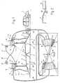
- a motor vehicle moves from the right to the left towards the swivel plate unit 5 consisting of swivel plates 2, 3 und 4.
- the middle swivel plate 3, being said first swivel plate referred to herein, is preferably near its middle portion swiveling on bearing block 7 around an axis being horizontal and transverse with respect to the traffic lane.
- first storage container 8 and a second storage container 9 for water- and compressed air are fixed. Both comprise two parts, i.e. an upper container 10 being open to atmosphere and a closed pressure equalizing container 11, partly filled with water and partly filled with compressed air.
- a first pressure resistent hose 12 is lead out of the part filled with air of the pressure equalizing container 11 of the first storage container B and is directed to a first flexible air container 13 disposed underneath the swivel plates 2 and 3.
- a second pressure resistent hose 14 is directed from the part filled with air of the pressure equalizing container of the second storage container 9 towards a second flexible air container 15 disposed underneath the swivel plates 3 and 4.
- Both hoses are open towards the flexible air containers, respectively, while they are provided with a nonreturn valve 16 towards the pressure equalizing container 11.
- a hose 18 is lead which is provided with a nonreturn valve 17 at the side of the container and the other side of which leads to a first turbine 19.
- another hose 21 is lead to the second storage container 9 and provided with a nonreturn valve 20 at the side of the storage container, while its other end leads to a second turbine 22.
- the nonreturn valve 20 of the second storage container 9 can be opened by signal transmitter 23, while nonreturn valve 17 of the first storage container 8 can be opened by a signal of signal transmitter 24.
- nonreturn valve 20 is opened and water is urged by means of compressed air within pressure equalizing container 11 through the turbine 22. From the outlet of turbine 22 water flows towards part 10 of the first storage container 8 being open to atmosphere.
- vehicle 1 drives on swivel plate 2, wherein the plate 3 is linked to it and pivoted on bearing block 7 and turns around an axis being horizontal and transverse with respect to the traffic lane.
- the flexible air containers 13 filled with air and disposed under plates 2 and 3 are squeezed together urging out compressed air through the first hose 12 into the pressure equalizing container of the first storage container 8.
- nonreturn valve 16 opens by itself.
- nonreturn valve 17 of the first storage container 8 is opened and water is urged by the compressed air drawn up before within pressure equalizing container 11 of the first storage container 8 through hose 18 into turbine 19, the outlet of which terminates in part 10 of the second storage container 9 open to atmosphere, whereby the force of gravity of the container 9 assist in forcing plate 3 to turn in the other direction, whereby the storage of compressed air within the second storage container 9 which had been used up before is rebuilt, after nonreturn valve 25 had opened under the pressure of the water within part 10 of the second storage container 9 and hence pressure equalizing container 11 had been refilled with water. By means of the pressure being rebuild within pressure equalizing container 11 the nonreturn valve 25 is closed again.
- the plate 3 returns thereby by itself into a certain predetermined position. Thereby the nonreturn valves 27 of the flexible air containers 13 or 15, respectively, open and render possible that fresh air can pass into the air containers.
- the pressure equalizing container 11 is partly filled with water and the pressure within the pressure equalizing container is the same as the atmosheric pressure, while the part 10 of the second storage container 9 being open to atmosphere is filled with water as well as the pressure equalizing container 11 is partly filled with water and partly filled with compressed air.
- the installation according to the invention further comprises at least one second swivel plate arrangement 35, which is shown in fig.1 only by reason of figuring below the first swivel plate arrangement 5 and which actually is located laterally of the first swivel plate arrangement outside of the traffic lane.
- the second swivel plate arrangement 35 comprises a second swivel plate 33, which also centrally is rotatingly supported on a second bearing block 37.
- additional flexible air containers 43 and 45 are provided which at the one hand are attached to the swivel plate 33 and at the other hand are attached to stationary supports 46 and 47.
- the flexible air containers are also connected to the pressure equalisizing containers 11 through pressure resistent flexible hoses 42, 44 and nonreturn valves 16 or additional nonreturn valves.
- the swivel plate 33 is coupled with the swivel plate 3 of swivel plate arrangement 5 by means of power transmissions 48, which are only schematically shwon by dash and dot lines, in such a way that the swivel motions of the swivel plate 3 are transmitted to the swivel plate 33 so that the latter is also rotated up and down and therefore the air containers 43 and 45 are alternately compressed for compressing air and pumping the compressed air into the respective pressure equalizing container 11 and extended again for sucking-in enviromental air through additional nonreturn valves not shown.
- Fig. 2 schematically shows such a power transmission 48 in form of a two-arm swivel lever, being stationarily supported and engaging with its lever arm the swivel plate 3 and the swivel plate 33, respectively.
- the lever arms of swivel lever can be differently long in order to provide for a larger swivel stroke of swivel plate 33 than of swivel plate 3.
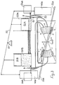
- Fig. 3 shows a further embodiment of the invention wherein an additional right weight 40A and an additional left weight 40B help to swivel the additional swivel plate 33.
- the weights 40A and 40B are connected to a swivel rod 50 pivoted on a bearing block 51.
- the swivel rod 51 is swiveled by a right swimmer 52A floating within a right water container 20A and a left swimmer 52B floating within a left water container 20B, thereby moving said first weight down onto the right end portion of the second swivel plate 33 and the left weight up from said left end portion of the second swivel plate 33 and helping to urge air out of the second flexible containers 43 and 45.
- the mechanism of swiveling the swivel rod 51 is as follows: Besides a pipe or hose 12 leading to the turbine 19 the second flexible container 45 is connected by a further hose 53 to a right water container 20A. When air is urged out of the flexible container 45 as described with reference to Fig. 1, it is pressed via hose 53 into the right water container 20A urging water within this container 20A via a further hose into the left water container 20B. As a result, the swimmer 52A within the right water container 20A is lowered and the swimmer 52B within the left water container 20B is moved up. This causes, that the right weight 40A is lowered onto the right end portion 33A of the second swivel plate 33.
- the right weight 40A helps to urge air out of the flexible containers 43 and 45.
- the right swimmer 52A is moved up and the left swimmer 52B is moved down in the above mentioned way, causing the opposite reaction and helping again to urge air out the flexible containers 43 and 45.
- non return valves it is realized, that the air and water is not released before it should be released.
- the air in the flexible containers 43 and 45 is pre-compressed to realize a higher pressure.
- right and left reserve air pressure containers 54A, 54B are connected to the right and left water containers 20A and 20B, opening towards these water containers 20A, 20B by means of a valve responsive on a electronic signal due to the position of the car. Additional air pressure may also be applied by a further swivel plate urging out air and being actuated by a car.
Landscapes
- Engineering & Computer Science (AREA)
- Mechanical Engineering (AREA)
- General Engineering & Computer Science (AREA)
- Chemical & Material Sciences (AREA)
- Combustion & Propulsion (AREA)
- Other Liquid Machine Or Engine Such As Wave Power Use (AREA)
- Compressors, Vaccum Pumps And Other Relevant Systems (AREA)
Abstract
Description
- This invention relates to an installation for generating utilizable energy from potential energy of slowly driving motor vehicles of the street traffic, wherein the machinery comprises at least one rigid swivel plate to be overtravelled by the motor vehicles and beared on a bearing block, the plate being lowerable under the weight of a motor vehicle, wherein a fluid being able to flow is urged out of flexible containers and directed into a pressure equalizing container being connected with a turbine or a hydraulic motor.
- Such an installation for generating utilizable energy from potential energy of motor vehicles of street traffic is already known from the US-PS 4,339,920. According to this patent a plurality of flexible containers, which are filled with an incompressible fluid, are squeezed together, and subsequently the fluid is directed, may be after passing a flexible and hence extendable container, to a hydraulic motor for generating utilizable energy: The containers being compressible by the weight of a motor vehicle are disposed in small chambers which are inserted within the traffic lane, whereby the covers of these chambers can be urged by the weight of a motor vehicle into a position underneath the surface of the traffic lane. Thereby the tire of the motor vehicle is hit very hard like in case of driving through potholes.
- Furthermore, an installation for generating utilizable energy from potential energy of motor vehicles is known from DE-OS 35 42 031. According to this specification, flexible containers filled with water are compressed by means of rigid swivel plates and the urged out water is fed for generating energy into a turbine.
- It has shown to be a disadvantage of this installation, that there have to be taken special measures for driving back the urged out water into the flexible containers and thereby to move back the swivel plates into their original position. Furthermore, it has shown to be disadvantageous to urge an incompressible fluid out of the flexible containers, because in this case the energy cannot be accumulated without taking additional measures in form of a fluid under pressure and hence a turbine cannot be driven in an optional moment.
- In order to render possible to accumulate energy in form of a fluid under pressure and furthermore to utilize the force of gravity of the water flowing out of the turbine, additionally for generating energy, it was further proposed (WO 90/08259) that the fluid being urged out of the flexible containers into the water-bearing pressure equalizing container is air which presses water through the turbine and through the hydraulic motor, respectively, and a storage container for water is positioned subsequently behind the turbine of the hydraulic motor, respectively, and the storage container is pivotably supported on the swivel plate on both sides of the bearing block, whereby the storage container assists in lowering the swivel plate and hence assists in driving out the air, wherein filling the storage containers is controlled by motor vehicle-actuated signal transmitters which open and close valves, in such a way that the suitable storage container is exactly filled in the right moment so that it actually assists in lowering the plate caused by the motor vehicle.
- An object of the invention is to further develop an installation of the present kind in such a way that the efficieny of the installation is further increased, even if the swivel mechanism has a small concruction height with only a small swivel stroke of the swivel plate.
- In meeting this object the invention is an installation for generating utilizable energy from potential energy of slowly driving motor vehicles of the street traffic, comprising a rigid first swivel plate being built in a traffic lane and being centrally pivoted, said first swivel plate being supported on flexible first air containers to be compressed by the swiveling of the first swivel plate and being coupled by means of a power transmission with a rigid second swivel plate being located laterally of the first swivel plate outside the traffic lane and being centrally supported, additional flexible air containers being supported at said second swivel plate to be compressed by the swiveling of said second swivel plate, said air containers being connected through compressed-air lines to at least one water-bearing pressure equalizing container connected through a water line with a hydraulic motor, especially with a turbine, to press water through the turbine and through the hydraulic motor, respectively, said hydraulic motor and turbine, respectively, being connected with its outlet to water storage containers connectable to the pressure equalizing container and pivotably supported by one of the swivel plates whereby the storage container assist in lowering the swivel plate and hence assist in compressing the air containers, wherein filling the storage containers is controlled by motor vehicle-actuated signal transmitters which open and close valves, in such a way, that the suitable storage container is exactly filled at the right moment so that it actually assists in lowering the plate caused by the motor vehicle.
- Due to arranging, according to the invention, a second swivel plate, which is coupled with the first swivel plate for transmission of motion and which can be arranged laterally of the traffic lane without limitation of its construction height and by which additional air in additional flexible air containers is compressed and pumped into the pressure equilizing container to expel the water into the hydraulic motor and the turbine, respectively, which is driven thereby, a more complete utilization of the potential energy of the motor vehicles passing over the first swivel plate can be reached even if the swiveling strokes of the first swivel plate are small.
- Herein, the power transmission can be constructed as an step-up transmission so that the swiveling stroke of the second swivel plate is larger than that of the first swivel plate. Said power transmission is preferably constructet as a lever transmission, though other suitable power transmissions could be used.
- The storage containers can be supported at both sides of the swivel axis of the first swivel plate or of the second swivel plate. From the water storage containers the water is redelivered into the pressure equalizing container.
- According to a preferred embodiment, the additional second water bearing pressure equalizing containers and additional second water storage containers are supported on the additional second swivel plate, these containers having the same construction as the containers supported on the first swivel plate helping to urge air out of said second flexible air containers.
- According to another preferred embodiment of the invention the installation further comprises a right end portion and a left end portion of said second swivel plate; a right heavy weight and a left heavy weight being in operational connection with the right and left end portions and a swivel rod pivoted at it's middle portion on a bearing block; a right and a left water container; and a right and a left swimmer inside the right and the left water containers, respectively, wherein the swivel rod is connected at it's right and left side with the right and left swimmer and the right and left weight, respectively, the additional flexible air containers being connected to the right and left water containers urging water out of the right water container into the left water container or vice versa, forcing the right swimmer to to move up and the left swimmer to move down or vice versa, thereby swiveling the swivel rod and lowering the right weight onto the right end portion of the swivel plate, or vice versa onto the left end portion, for helping to swivel said second swivel plate and therefore helping to urge air out of said additional flexible air containers.
- According to another preferred embodiment the installation comprises reserve air pressure containers, providing additional air for urging water out of the right water container into the left water container or vice versa, the reserve air container being opened by a valve responsive to an electronic signal according to the position of the car.
- Due to the small construction height of the first swivel plate, the first swivel plate can especially be built into the traffic lane as a bumpiness causing threshold for slowing down the traffic. On the other hand, it is possible to build in the first swivel plate in or on the traffic lane in front of a traffic light for motor vehicles or in or on a sidewalk in front of a pelican crossing.
- In the following the invention will be described more detailedly with the help of preferred embodiments and with reference to the accompanying drawings.
- In the drawings shows:
- Fig. 1
- a construction scheme of a first embodiment of the invention, and
- Fig. 2
- schematically a transmission of motion between two swivel plates.
- Fig. 3
- a construction scheme of a second embodiment of the invention.
- As shown in figure 1, a motor vehicle moves from the right to the left towards the
swivel plate unit 5 consisting ofswivel plates - The middle
swivel plate 3, being said first swivel plate referred to herein, is preferably near its middle portion swiveling on bearingblock 7 around an axis being horizontal and transverse with respect to the traffic lane. - Near or directly at the hinges 6 a
first storage container 8 and asecond storage container 9 for water- and compressed air is fixed. Both comprise two parts, i.e. anupper container 10 being open to atmosphere and a closedpressure equalizing container 11, partly filled with water and partly filled with compressed air. - A first pressure
resistent hose 12 is lead out of the part filled with air of thepressure equalizing container 11 of the first storage container B and is directed to a firstflexible air container 13 disposed underneath theswivel plates - Analogically, a second pressure
resistent hose 14 is directed from the part filled with air of the pressure equalizing container of thesecond storage container 9 towards a second flexible air container 15 disposed underneath theswivel plates 3 and 4. - Both hoses are open towards the flexible air containers, respectively, while they are provided with a
nonreturn valve 16 towards thepressure equalizing container 11. Into the part of thefirst storage container 8 which is filled with water ahose 18 is lead which is provided with anonreturn valve 17 at the side of the container and the other side of which leads to afirst turbine 19. Analogically, anotherhose 21 is lead to thesecond storage container 9 and provided with anonreturn valve 20 at the side of the storage container, while its other end leads to asecond turbine 22. - The
nonreturn valve 20 of thesecond storage container 9 can be opened bysignal transmitter 23, whilenonreturn valve 17 of thefirst storage container 8 can be opened by a signal ofsignal transmitter 24. When the approaching vehicletouches signal transmitter 23,nonreturn valve 20 is opened and water is urged by means of compressed air withinpressure equalizing container 11 through theturbine 22. From the outlet ofturbine 22 water flows towardspart 10 of thefirst storage container 8 being open to atmosphere. At thesame moment vehicle 1 drives onswivel plate 2, wherein theplate 3 is linked to it and pivoted onbearing block 7 and turns around an axis being horizontal and transverse with respect to the traffic lane. As a result of this turning movement theflexible air containers 13 filled with air and disposed underplates first hose 12 into the pressure equalizing container of thefirst storage container 8. Therebynonreturn valve 16 opens by itself. - Because in the meantime a sufficient amount of water has passed
turbine 22 into thefirst storage container 8 , the force of gravity of thefirst storage container 8 which is supported nearhinge 6 connectingplate 2 andplate 3 assist in squeezing together the firstflexible air container 13, whereby it assists in drawing up a storage of compressed air withinpressure equalizing container 11 ofstorage container 8. When the vehicle reaches bearingblock 7 being disposed near thesecond signal transmitter 24,nonreturn valve 17 of thefirst storage container 8 is opened and water is urged by the compressed air drawn up before withinpressure equalizing container 11 of thefirst storage container 8 throughhose 18 intoturbine 19, the outlet of which terminates inpart 10 of thesecond storage container 9 open to atmosphere, whereby the force of gravity of thecontainer 9 assist in forcingplate 3 to turn in the other direction, whereby the storage of compressed air within thesecond storage container 9 which had been used up before is rebuilt, afternonreturn valve 25 had opened under the pressure of the water withinpart 10 of thesecond storage container 9 and hencepressure equalizing container 11 had been refilled with water. By means of the pressure being rebuild withinpressure equalizing container 11 thenonreturn valve 25 is closed again. - When the vehicle leaves plate 4 and hence the whole installation, the storage of compressed air within the
pressure equalizing container 11 of thefirst storage container 8 is used up again and no water is left within the pressure equalizing container. This causes thatnonreturn valve 26 of thefirst storage container 8 opens under the pressure of the water withinpart 10 of the storage container being open to atmosphere and discharges into the pressure equalizing container filling it with water again. That means that the final state, i.e. the state after the vehicle has left the installation, is the same as the original state, i.e. the state before the vehicle was driven onto the installation. - The
plate 3 returns thereby by itself into a certain predetermined position. Thereby thenonreturn valves 27 of theflexible air containers 13 or 15, respectively, open and render possible that fresh air can pass into the air containers. - That means that in the original and the final states the
part 10 of thefirst storage container 8 being open to atmosphere is empty, thepressure equalizing container 11 is partly filled with water and the pressure within the pressure equalizing container is the same as the atmosheric pressure, while thepart 10 of thesecond storage container 9 being open to atmosphere is filled with water as well as thepressure equalizing container 11 is partly filled with water and partly filled with compressed air. - Hence, if a following vehicle drives onto the installation, the whole procedure can take place again, whereby the
turbines - Because the supplying of energy by the vehicles takes place discontinuously, i.e. temporalily not constant, it is convenient to provide the
turbines - The installation according to the invention further comprises at least one second
swivel plate arrangement 35, which is shown in fig.1 only by reason of figuring below the firstswivel plate arrangement 5 and which actually is located laterally of the first swivel plate arrangement outside of the traffic lane. The secondswivel plate arrangement 35 comprises a secondswivel plate 33, which also centrally is rotatingly supported on a second bearingblock 37. Above and below the swivel plate at both sides of thebearing block 37 and spaced therefrom additionalflexible air containers swivel plate 33 and at the other hand are attached tostationary supports containers 11 through pressure resistent flexible hoses 42, 44 andnonreturn valves 16 or additional nonreturn valves. Theswivel plate 33 is coupled with theswivel plate 3 ofswivel plate arrangement 5 by means ofpower transmissions 48, which are only schematically shwon by dash and dot lines, in such a way that the swivel motions of theswivel plate 3 are transmitted to theswivel plate 33 so that the latter is also rotated up and down and therefore theair containers pressure equalizing container 11 and extended again for sucking-in enviromental air through additional nonreturn valves not shown. - Fig. 2 schematically shows such a
power transmission 48 in form of a two-arm swivel lever, being stationarily supported and engaging with its lever arm theswivel plate 3 and theswivel plate 33, respectively. The lever arms of swivel lever can be differently long in order to provide for a larger swivel stroke ofswivel plate 33 than ofswivel plate 3. - Instead of supporting the
water storage containers 10 and thepressure equalizing container 11 integrated therein on firstswivel plate 3, it is possible to support them on secondswivel plate 33. Further, it is possible to provide forsuch containers swivel plate 3 and onswivel plate 33. - Fig. 3 shows a further embodiment of the invention wherein an additional
right weight 40A and an additional left weight 40B help to swivel the additionalswivel plate 33. For this reason, theweights 40A and 40B are connected to aswivel rod 50 pivoted on abearing block 51. Theswivel rod 51 is swiveled by aright swimmer 52A floating within aright water container 20A and a left swimmer 52B floating within aleft water container 20B, thereby moving said first weight down onto the right end portion of thesecond swivel plate 33 and the left weight up from said left end portion of thesecond swivel plate 33 and helping to urge air out of the secondflexible containers swivel rod 51 is as follows: Besides a pipe orhose 12 leading to theturbine 19 the secondflexible container 45 is connected by afurther hose 53 to aright water container 20A. When air is urged out of theflexible container 45 as described with reference to Fig. 1, it is pressed viahose 53 into theright water container 20A urging water within thiscontainer 20A via a further hose into theleft water container 20B. As a result, theswimmer 52A within theright water container 20A is lowered and the swimmer 52B within theleft water container 20B is moved up. This causes, that theright weight 40A is lowered onto theright end portion 33A of thesecond swivel plate 33. In this state, theright weight 40A helps to urge air out of theflexible containers left portion 33B of thesecond swivel plate 33 is lowered, theright swimmer 52A is moved up and the left swimmer 52B is moved down in the above mentioned way, causing the opposite reaction and helping again to urge air out theflexible containers - According to further improvements of the embodiment according to fig. 3, the air in the
flexible containers air pressure containers 54A, 54B are connected to the right and leftwater containers water containers
Claims (9)
- An installation for generating utilizable energy from potential energy of slowly driving motor vehicles of the street traffic, comprising a rigid first swivel plate (3) being built in a traffic lane and being centrally pivoted, said first swivel plate being supported on flexible first air containers (13, 15) to be compressed by the swiveling of the first swivel plate and being coupled by means of a power transmission (48) with a rigid second swivel plate (33) being located laterally of the first swivel plate outside the traffic lane and being centrally supported, additional flexible air containers (43, 45) supported at said second swivel plate to be compressed by the swiveling of said second swivel plate, said air containers (13, 15, 43, 45) being connected through compressed-air lines to at least one water-bearing pressure equalizing container (11) connected through a water line with a hydraulic motor, especially with a turbine (19, 22), to press water through the turbine and through the hydraulic motor, respectively, said hydraulic motor and turbine, respectively, being connected with its outlet to water storage containers (10) connectable to the pressure equalizing container and pivotably supported by one of the swivel plates (3, 33), whereby the storage container assist in lowering the swivel plate and hence assist in compressing the air containers, wherein filling the storage containers is controlled by motor vehicle-actuated signal transmitters (23, 24) which open and close valves (17, 20), in such a way, that the suitable storage container is exactly filled at the right moment so that it actually assists in lowering the plate caused by the motor vehicle.
- The installation according to claim 1, wherein said power transmission (48) is constructed as an step-up transmission so that the swiveling stroke of the second swivel plate (33) is larger than that of the first swivel plate (3).
- The installation according to claim 1, wherein said power transmission (48) is constructet as a lever transmission.
- The installation according to claim 1, wherein additional second water bearing pressure equalizing containers (11) and additional second water storage containers (10) are supported on the additional second swivel plate (33), these containers (10,11) having the same construction as the containers (10,11) supported on the first swivel plate (3), helping to urge air out of said second flexible air containers (43,45).
- The installation according to claim 1, further comprising a right end portion (33A) and a left end portion (33B) of said second swivel plate (33); a right heavy weight (40A) and a left heavy weight (40B) being in operational connection with the right and left end portions (33A,33B) and a swivel rod (50) pivoted at it's middle portion on a bearing block (51); a right and a left water container (20A,20B); and a right and a left swimmer (52A,52B) inside the right and the left water containers (20A,20B), respectively, wherein the swivel rod (50) is connected at it's right and left side with the right and left swimmer (52A,52) and the right and left weight (40A,40B), respectively, the additional flexible air containers (43,45) being connected to the right and left water containers (20A,20B) urging water out of the right water container (20A) into the left water container (20B) or vice versa, forcing the right swimmer (52A) to to move up and the left swimmer (52B) to move down or vice versa, thereby swiveling the swivel rod (50) and lowering the right weight (40A) onto the right end portion (33A) of the swivel plate (33), or vice versa onto the left end portion (33B), for helping to swivel said second swivel plate (33) and therefore helping to urge air out of said additional flexible air containers (43,45).
- The installation according to claim 5, further comprising reserve air pressure containers (54A,54B), providing additional air for urging water out of the right water container (20A) into the left water container (20B) or vice versa, the reserve air containers (54A,54B) being opened by a valve responsive to an electronic signal according to the position of the car.
- The installation according to claim 1, wherein the first swivel plate (39 is built into the traffic lane as a bumpiness causing threshold in a traffic calmed zone.
- The installation according to claim 1, wherein the first swivel plate (3) is built into the traffic lane in front of a traffic light.
- The installation according to claim 1, wherein the first swivel plate (3) is built into a sidewalk in front of a pelican crossing traffic light.
Applications Claiming Priority (3)
| Application Number | Priority Date | Filing Date | Title |
|---|---|---|---|
| DE9013326 | 1990-09-20 | ||
| DE9013326U | 1990-09-20 | ||
| PCT/EP1991/001802 WO1992005366A1 (en) | 1990-09-20 | 1991-09-20 | Installation for generating utilizable energy from potential energy |
Publications (2)
| Publication Number | Publication Date |
|---|---|
| EP0548147A1 EP0548147A1 (en) | 1993-06-30 |
| EP0548147B1 true EP0548147B1 (en) | 1995-07-12 |
Family
ID=6857694
Family Applications (1)
| Application Number | Title | Priority Date | Filing Date |
|---|---|---|---|
| EP91916022A Expired - Lifetime EP0548147B1 (en) | 1990-09-20 | 1991-09-20 | Installation for generating utilizable energy from potential energy |
Country Status (9)
| Country | Link |
|---|---|
| US (1) | US5355674A (en) |
| EP (1) | EP0548147B1 (en) |
| JP (1) | JPH06500610A (en) |
| AU (1) | AU8509291A (en) |
| BR (1) | BR9106873A (en) |
| DE (1) | DE69111244D1 (en) |
| ES (1) | ES2076545T3 (en) |
| RU (1) | RU2063548C1 (en) |
| WO (1) | WO1992005366A1 (en) |
Families Citing this family (75)
| Publication number | Priority date | Publication date | Assignee | Title |
|---|---|---|---|---|
| US5634774A (en) * | 1996-03-01 | 1997-06-03 | Angel; Robert C. | Road vehicle-actuated air compressor |
| RU2139446C1 (en) * | 1997-01-06 | 1999-10-10 | Станция юных техников города Костромы | Compressor unit |
| US5955790A (en) * | 1998-03-13 | 1999-09-21 | North; Vaughn W. | Apparatus for converting tide/wave motion to electricity |
| US6091159A (en) | 1998-10-05 | 2000-07-18 | Galich; Thomas P. | Electrical energy producing platform and method of use |
| US6376925B1 (en) | 1998-10-05 | 2002-04-23 | Thomas P. Galich | Force stand for electrical energy producing platform |
| DE19904741C2 (en) * | 1999-02-05 | 2001-12-20 | Josef Padera | Auto-kinetic energy power plant |
| US6362534B1 (en) | 1999-08-26 | 2002-03-26 | William M. Kaufman | Apparatus and method for extracting energy from a passing train |
| BG104800A (en) * | 2000-09-26 | 2002-03-29 | ПЕТРОВ Зафир | AUTONOMOUS STATUS FOR RECEIVING ENERGY |
| BR0103310A (en) * | 2001-06-18 | 2003-03-05 | Jose Raimundo Dos Santos | Electricity generation system |
| US6767161B1 (en) * | 2001-12-05 | 2004-07-27 | Calvo Rafael A | Highway electric power generator |
| US6756694B2 (en) * | 2002-01-15 | 2004-06-29 | Tod Ricketts | Apparatus for generating power from passing vehicular traffic |
| US6949840B2 (en) * | 2002-01-15 | 2005-09-27 | Ricketts Tod A | Apparatus for generating power from passing vehicular traffic |
| US20030160454A1 (en) * | 2002-02-25 | 2003-08-28 | John Manolis | Renewabel gravity, wind and solar energy engine |
| IL151591A0 (en) * | 2002-09-04 | 2003-04-10 | Moshe Alperon | Energy generation system |
| US20060225416A1 (en) * | 2002-12-31 | 2006-10-12 | North Vaughn W | Underwater wave/energy transducer |
| US7768144B2 (en) * | 2002-12-31 | 2010-08-03 | Vaughn W North | Underwater wave/energy transducer |
| US7005757B2 (en) * | 2003-02-18 | 2006-02-28 | Shunmugham Rajasekara Pandian | Pneumatic human power conversion system based on children's play |
| US6969213B2 (en) * | 2003-02-24 | 2005-11-29 | Omnitek Partners, Llc | Roadway for decelerating and/or accelerating a vehicle including an aircraft |
| US7429145B2 (en) * | 2003-02-24 | 2008-09-30 | Omnitek Partners L.L.C. | Bi-directional roadway for decelerating a vehicle including an aircraft |
| US20040189009A1 (en) * | 2003-03-27 | 2004-09-30 | Galich Thomas P. | Electrical energy generation system |
| ITCA20030004A1 (en) * | 2003-07-09 | 2003-10-07 | Fernando Erriu | MACHINE TO TRANSFORM THE PASSAGE OF VEHICLES INTO THE ROADS, ROAD CIRCULATION IN A PRIMARY ALTERNATIVE SOURCE TO PRODUCE POT ENERGY |
| WO2005005831A1 (en) | 2003-07-09 | 2005-01-20 | Fernando Erriu | A fluid device for recovery of the kinetic energy of a vehicle |
| US20050253459A1 (en) * | 2004-05-14 | 2005-11-17 | Cole Francis W | Rotary energy conversion device |
| US7067932B1 (en) * | 2005-01-07 | 2006-06-27 | Faramarz Frank Ghassemi | System for generating electricity by using gravitational mass and/or momentum of moving vehicle |
| US20070020047A1 (en) * | 2005-07-21 | 2007-01-25 | Sarah Adair | Hydraulic roadbed electricity generating apparatus and method |
| US7629698B2 (en) * | 2005-10-19 | 2009-12-08 | Dimitrios Horianopoulos | Traffic-actuated electrical generator apparatus |
| US7498685B2 (en) * | 2005-11-09 | 2009-03-03 | Timothy John Emmanuel Turner | Electrical generator |
| ES2304278B1 (en) * | 2006-01-03 | 2009-07-27 | Juan Reyes Florido | SYSTEM FOR THE USE OF THE FORCE OF GRAVITY. |
| WO2007079742A1 (en) * | 2006-01-16 | 2007-07-19 | Madhukar Dange | Method and device for converting potential energy in kinetic energy for producing energy |
| US7530760B2 (en) * | 2006-02-21 | 2009-05-12 | Omnitek Partners Llc | Roadway for decelerating a vehicle including a delayed release means for depressed runway panels |
| WO2007133172A1 (en) * | 2006-05-15 | 2007-11-22 | Alexandr Viktorovich Martianov | Arrangement for converting the pressure of moving transport means into electric power and a roadway surfacing device for said plant |
| MX2009003077A (en) * | 2006-09-20 | 2009-04-16 | Innovative Patents Ltd | ELECTRICITY CONVERTER BY VEHICLE CIRCULATION INCORPORATED WITHIN A ROAD STOP. |
| US20080106103A1 (en) * | 2006-11-08 | 2008-05-08 | Willie Adam Owens | Road surface generator or "RSG" device |
| WO2008156606A2 (en) * | 2007-06-12 | 2008-12-24 | Adrian Pelkus | Thin film piezoelectric wave power generation system |
| ITPD20070298A1 (en) * | 2007-09-19 | 2009-03-19 | Lorenzo Callegari | P.P.E.E. ELECTRIC ENERGY PRODUCTION PLATFORM |
| US8080895B1 (en) * | 2007-10-12 | 2011-12-20 | Williams Brian B | Energy generation from compressed fluids |
| US7905678B2 (en) * | 2007-10-30 | 2011-03-15 | Omnitek Partners, Llc | Deployable collapsible engineered material systems for runway safety |
| US7541684B1 (en) * | 2007-11-21 | 2009-06-02 | Valentino Joseph A | Systems for generating useful energy from vehicle motion |
| NZ560238A (en) * | 2008-01-30 | 2010-07-30 | Enervate Ltd | System for recovering of kinetic energy from vehicles |
| US7898098B2 (en) * | 2008-03-13 | 2011-03-01 | Baitao Wang | Asymmetric hydraulic press electric generator |
| GB2459260A (en) * | 2008-04-15 | 2009-10-21 | Haruo Okamoto | Step-on electricity generator |
| US8148833B2 (en) * | 2008-09-20 | 2012-04-03 | Hung-Wei Chang | On-road energy conversion and vibration absorber apparatus |
| US20100072758A1 (en) * | 2008-09-20 | 2010-03-25 | Hung-Wei Chang | On-Road Energy Conversion and Vibration Absorber Apparatus |
| US8497589B2 (en) * | 2008-11-10 | 2013-07-30 | John Richard Geletka | Electricity production from static weight |
| EP2409032A4 (en) * | 2008-11-26 | 2017-03-08 | Kinetic Energy Corporation | Adaptive, low-impact vehicle energy harvester |
| CN102483184B (en) * | 2009-01-09 | 2015-05-20 | 动力能源公司 | Vehicle energy harvesting roadway |
| EP2411816B1 (en) * | 2009-01-27 | 2016-11-30 | Kinetic Energy Corporation | Vehicle speed detection means for power generation system |
| US8344527B2 (en) * | 2009-05-13 | 2013-01-01 | Phoenix Renewable Energy, Inc. | Apparatus for converting momentum into useful work |
| TWI605193B (en) * | 2009-12-11 | 2017-11-11 | 徐郁輝 | Potential energy regeneration system and method, and power regeneration system and method |
| US8232661B2 (en) * | 2010-05-28 | 2012-07-31 | Richard Thomas Cannarella | System and method for generating and storing clean energy |
| US8740497B2 (en) * | 2010-09-22 | 2014-06-03 | John L. Gohmann | Roadway arrangement for power generation |
| US20120112471A1 (en) * | 2010-11-05 | 2012-05-10 | Jozo Karoglan | Energy plant powered by air pressure |
| US8344529B2 (en) * | 2011-01-18 | 2013-01-01 | Energy Intelligence, LLC | Method and system for energy harvesting |
| US8928160B2 (en) | 2011-02-17 | 2015-01-06 | Jack Shihzong Jang | Electrical generator apparatus, particularly for use on a vehicle roadway |
| US8164204B2 (en) * | 2011-02-17 | 2012-04-24 | Jack Shihzong Jang | Electrical generator apparatus, particularly for use on a vehicle roadway |
| US9287753B2 (en) | 2011-02-17 | 2016-03-15 | Jack Shihzong Jang | Electrical generator apparatus, particularly for use on a vehicle roadway |
| US20140042753A1 (en) * | 2011-03-03 | 2014-02-13 | Research Triangle Institute, International | Energy storage reservoir |
| US8288879B1 (en) * | 2011-08-02 | 2012-10-16 | Harper Jack R | Highway generator system |
| US9580472B2 (en) * | 2011-11-21 | 2017-02-28 | Board Of Regents Of The University Of Nebraska | Anti-microbial peptides and methods of use thereof |
| TW201407036A (en) * | 2012-08-01 | 2014-02-16 | 馮金星 | Mutual traction actuator |
| US10408195B2 (en) | 2013-04-15 | 2019-09-10 | Kinergypower International Corp. | Railroad kinetic energy harnessing apparatus |
| US9068467B2 (en) * | 2013-07-26 | 2015-06-30 | Chuan-Yu Hung | Electric power generation assembly |
| ITMI20131419A1 (en) * | 2013-08-28 | 2015-03-01 | Tagliacani Dott Ssa Cristina Vanelli | EQUIPMENT FOR THE PRODUCTION OF ELECTRICITY, EXPLOITING THE TRANSIT OF ROAD VEHICLES |
| US9834892B2 (en) * | 2013-09-09 | 2017-12-05 | King Fahd University Of Petroleum And Minerals | Pneumatic roadway energy recovery system |
| US9670912B2 (en) * | 2014-01-27 | 2017-06-06 | Frank J. Alvino | Electric power generation system for roadway use |
| EP3177825A1 (en) | 2014-08-07 | 2017-06-14 | Amar S. Wanni | Wave energy converter |
| US9641045B2 (en) * | 2014-10-02 | 2017-05-02 | Bill Lewis, SR. | Electromagnetic platform motor (EPM) (EPM-1) (EPM-2) |
| ES2648521B1 (en) * | 2016-06-30 | 2018-10-22 | Sergio Rafael VEGA CAMA | Potential energy storage system and electric power generation |
| US10879765B2 (en) * | 2017-07-06 | 2020-12-29 | Musbah Ali Lahib | Generator system utilizing transportation weights and propulsion on roads |
| EP3669070B1 (en) * | 2017-08-15 | 2022-01-26 | The University of North Florida Board of Trustees | Integrated system for optimal extraction of head-driven tidal energy with minimal or no adverse environmental effects |
| AU2019228537A1 (en) | 2018-02-28 | 2020-09-17 | Constructis Group, Inc. | Systems and methods for capturing kinetic energy and for emission-free conversion of captured energy to electricity |
| US10844830B1 (en) | 2019-12-14 | 2020-11-24 | Amar S. Wanni | Wave energy converter |
| GB2639528B (en) * | 2024-01-09 | 2026-04-08 | R2E Entpr Ltd | A kinetic energy harvesting system |
| GB2637142A (en) * | 2024-01-09 | 2025-07-16 | Rouute Energy Ltd | A kinetic energy harvesting system |
| GB2631684A (en) * | 2023-07-12 | 2025-01-15 | Rouute Energy Ltd | Kinetic energy harvesting system |
Family Cites Families (18)
| Publication number | Priority date | Publication date | Assignee | Title |
|---|---|---|---|---|
| US159660A (en) * | 1875-02-09 | Improvement in modes of obtaining motive power | ||
| US1833979A (en) * | 1930-11-12 | 1931-12-01 | Swindle Solomon Clifford | Automobile greasing rack |
| US2020361A (en) * | 1934-06-16 | 1935-11-12 | Clarence W H Johnston | Air compressor |
| US3803422A (en) * | 1971-10-18 | 1974-04-09 | F Krickler | Displacement hydro electric generator apparatus |
| US4180976A (en) * | 1978-04-27 | 1980-01-01 | Bunn Carl H | Siphon motor |
| US4212598A (en) * | 1978-07-20 | 1980-07-15 | Energy Development Corporation | Traffic-operated air-powered generating system |
| US4238687A (en) * | 1978-11-30 | 1980-12-09 | Santiago Martinez | Highway turbine |
| US4239975A (en) * | 1979-04-30 | 1980-12-16 | Chiappetti Arthur B | Energy producing system |
| DE2941079A1 (en) * | 1979-10-10 | 1981-04-23 | Zimmer, Cornelius P., 5308 Rheinbach | Vehicular energy re-cycling system - converts vehicle energy into stored potential energy using hinged road sections coupled to pump |
| JPS56113069A (en) * | 1980-02-13 | 1981-09-05 | Taiichi Shiraiwa | Generator on road |
| JPS56146079A (en) * | 1980-04-05 | 1981-11-13 | Keisuke Kotake | Utilization of gravity energy |
| US4427015A (en) * | 1980-06-06 | 1984-01-24 | Redeaux Jr Ralph | Syringe for use in the withdrawal of arterial blood |
| US4339920A (en) * | 1980-06-27 | 1982-07-20 | Le Van Wayne P | Method and apparatus utilizing the weight of moving traffic to produce useful work |
| US4409489A (en) * | 1980-09-26 | 1983-10-11 | Hayes Thomas J | Road traffic actuated generator |
| JPS6179880A (en) * | 1984-09-26 | 1986-04-23 | Ryohei Akai | Air pressure power apparatus for laying car road |
| US4980572A (en) * | 1985-06-24 | 1990-12-25 | Synchrosat Limited | Generation of electricity using gravitational energy |
| US4739179A (en) * | 1987-03-17 | 1988-04-19 | Stites Howard A | System for generating power by vehicle movement and methods of constructing and utilizing same |
| WO1990008259A1 (en) * | 1989-01-11 | 1990-07-26 | Baruch Rosenberg | Installation for extracting usable energy from potential energy |
-
1991
- 1991-09-20 AU AU85092/91A patent/AU8509291A/en not_active Abandoned
- 1991-09-20 RU RU9193005106A patent/RU2063548C1/en active
- 1991-09-20 WO PCT/EP1991/001802 patent/WO1992005366A1/en not_active Ceased
- 1991-09-20 US US08/027,155 patent/US5355674A/en not_active Expired - Lifetime
- 1991-09-20 EP EP91916022A patent/EP0548147B1/en not_active Expired - Lifetime
- 1991-09-20 BR BR919106873A patent/BR9106873A/en not_active IP Right Cessation
- 1991-09-20 DE DE69111244T patent/DE69111244D1/en not_active Expired - Lifetime
- 1991-09-20 JP JP3514921A patent/JPH06500610A/en active Pending
- 1991-09-20 ES ES91916022T patent/ES2076545T3/en not_active Expired - Lifetime
Also Published As
| Publication number | Publication date |
|---|---|
| JPH06500610A (en) | 1994-01-20 |
| WO1992005366A1 (en) | 1992-04-02 |
| DE69111244D1 (en) | 1995-08-17 |
| EP0548147A1 (en) | 1993-06-30 |
| RU2063548C1 (en) | 1996-07-10 |
| AU8509291A (en) | 1992-04-15 |
| BR9106873A (en) | 1993-07-06 |
| ES2076545T3 (en) | 1995-11-01 |
| US5355674A (en) | 1994-10-18 |
Similar Documents
| Publication | Publication Date | Title |
|---|---|---|
| EP0548147B1 (en) | Installation for generating utilizable energy from potential energy | |
| US5157922A (en) | Device for generating utilizable energy from potential energy | |
| US20040130158A1 (en) | System and method for electrical power generation utilizing vehicle traffic on roadways | |
| US4418542A (en) | Vehicular thoroughfares for power generation | |
| US7530761B2 (en) | System and method for electrical power generation utilizing vehicle traffic on roadways | |
| US4173431A (en) | Road vehicle-actuated air compressor and system therefor | |
| AU712078B2 (en) | Road speed limiting device | |
| US4583368A (en) | Water-powered hydraulic motor | |
| CN101278130B (en) | Hydraulic system for recovering potential energy | |
| US4208878A (en) | Ocean tide energy converter | |
| US12006921B2 (en) | Apparatus, systems, and methods for converting vehicular kinetic energy into electricity | |
| US20060147263A1 (en) | Apparatus for converting kinetic energy | |
| CN201249528Y (en) | Push-draw box mechanism used for detachable trash compressor | |
| US20080260560A1 (en) | Piston Pump for Thick Materials | |
| CN102303643B (en) | Transverse parking device of car | |
| GB2409112A (en) | Generating electric power from passing vehicle wheel. | |
| CN1113861A (en) | Motor vehicle mechanical energy collection and conversion device | |
| WO2007146807A2 (en) | Pressurized fluid-based power system for devices, such as vehicle drivetrains | |
| CN111980004B (en) | Portable highway basic unit compactness detects sampling device | |
| CN114717913A (en) | Automatic road bed tamping device of road construction | |
| CN208593683U (en) | A kind of dustbin toppled over convenient for rubbish | |
| CN208833354U (en) | A kind of overload detector with anti-strong prominent function | |
| CN2493577Y (en) | Hydraulic lifting vibration fully closed refuse collector | |
| CN2675514Y (en) | Hydraulic powered electric vehicle | |
| CN105003399A (en) | Power generation system utilizing rolling compaction force of wheels to pavement for power generation |
Legal Events
| Date | Code | Title | Description |
|---|---|---|---|
| PUAI | Public reference made under article 153(3) epc to a published international application that has entered the european phase |
Free format text: ORIGINAL CODE: 0009012 |
|
| AK | Designated contracting states |
Kind code of ref document: A1 Designated state(s): DE ES FR GR IT |
|
| 17P | Request for examination filed |
Effective date: 19930420 |
|
| 17Q | First examination report despatched |
Effective date: 19940208 |
|
| 18R | Application refused |
Effective date: 19931218 |
|
| D18R | Application refused (deleted) | ||
| RBV | Designated contracting states (corrected) |
Designated state(s): DE ES FR GB IT |
|
| GRAA | (expected) grant |
Free format text: ORIGINAL CODE: 0009210 |
|
| AK | Designated contracting states |
Kind code of ref document: B1 Designated state(s): DE ES FR GB IT |
|
| REF | Corresponds to: |
Ref document number: 69111244 Country of ref document: DE Date of ref document: 19950817 |
|
| PGFP | Annual fee paid to national office [announced via postgrant information from national office to epo] |
Ref country code: DE Payment date: 19950928 Year of fee payment: 5 |
|
| PG25 | Lapsed in a contracting state [announced via postgrant information from national office to epo] |
Ref country code: DE Effective date: 19951013 |
|
| REG | Reference to a national code |
Ref country code: ES Ref legal event code: FG2A Ref document number: 2076545 Country of ref document: ES Kind code of ref document: T3 |
|
| ET | Fr: translation filed | ||
| ITF | It: translation for a ep patent filed | ||
| PLBE | No opposition filed within time limit |
Free format text: ORIGINAL CODE: 0009261 |
|
| STAA | Information on the status of an ep patent application or granted ep patent |
Free format text: STATUS: NO OPPOSITION FILED WITHIN TIME LIMIT |
|
| 26N | No opposition filed | ||
| PGFP | Annual fee paid to national office [announced via postgrant information from national office to epo] |
Ref country code: GB Payment date: 20000314 Year of fee payment: 9 |
|
| PG25 | Lapsed in a contracting state [announced via postgrant information from national office to epo] |
Ref country code: GB Free format text: LAPSE BECAUSE OF NON-PAYMENT OF DUE FEES Effective date: 20000920 |
|
| PGFP | Annual fee paid to national office [announced via postgrant information from national office to epo] |
Ref country code: FR Payment date: 20010410 Year of fee payment: 10 |
|
| PGFP | Annual fee paid to national office [announced via postgrant information from national office to epo] |
Ref country code: ES Payment date: 20010430 Year of fee payment: 10 |
|
| GBPC | Gb: european patent ceased through non-payment of renewal fee |
Effective date: 20000920 |
|
| PG25 | Lapsed in a contracting state [announced via postgrant information from national office to epo] |
Ref country code: FR Free format text: LAPSE BECAUSE OF NON-PAYMENT OF DUE FEES Effective date: 20010531 |
|
| REG | Reference to a national code |
Ref country code: FR Ref legal event code: ST |
|
| PG25 | Lapsed in a contracting state [announced via postgrant information from national office to epo] |
Ref country code: ES Free format text: LAPSE BECAUSE OF NON-PAYMENT OF DUE FEES Effective date: 20010921 |
|
| REG | Reference to a national code |
Ref country code: ES Ref legal event code: FD2A Effective date: 20021011 |
|
| PG25 | Lapsed in a contracting state [announced via postgrant information from national office to epo] |
Ref country code: IT Free format text: LAPSE BECAUSE OF NON-PAYMENT OF DUE FEES Effective date: 20050920 |