EP0547883B1 - Cylinder lock with twisting tumblers - Google Patents
Cylinder lock with twisting tumblers Download PDFInfo
- Publication number
- EP0547883B1 EP0547883B1 EP19920311489 EP92311489A EP0547883B1 EP 0547883 B1 EP0547883 B1 EP 0547883B1 EP 19920311489 EP19920311489 EP 19920311489 EP 92311489 A EP92311489 A EP 92311489A EP 0547883 B1 EP0547883 B1 EP 0547883B1
- Authority
- EP
- European Patent Office
- Prior art keywords
- key
- cylinders
- parts
- lock
- blocking
- Prior art date
- Legal status (The legal status is an assumption and is not a legal conclusion. Google has not performed a legal analysis and makes no representation as to the accuracy of the status listed.)
- Expired - Lifetime
Links
Images


Classifications
-
- E—FIXED CONSTRUCTIONS
- E05—LOCKS; KEYS; WINDOW OR DOOR FITTINGS; SAFES
- E05B—LOCKS; ACCESSORIES THEREFOR; HANDCUFFS
- E05B27/00—Cylinder locks or other locks with tumbler pins or balls that are set by pushing the key in
- E05B27/0039—Cylinder locks or other locks with tumbler pins or balls that are set by pushing the key in with pins which slide and rotate about their axis
-
- Y—GENERAL TAGGING OF NEW TECHNOLOGICAL DEVELOPMENTS; GENERAL TAGGING OF CROSS-SECTIONAL TECHNOLOGIES SPANNING OVER SEVERAL SECTIONS OF THE IPC; TECHNICAL SUBJECTS COVERED BY FORMER USPC CROSS-REFERENCE ART COLLECTIONS [XRACs] AND DIGESTS
- Y10—TECHNICAL SUBJECTS COVERED BY FORMER USPC
- Y10T—TECHNICAL SUBJECTS COVERED BY FORMER US CLASSIFICATION
- Y10T70/00—Locks
- Y10T70/70—Operating mechanism
- Y10T70/7441—Key
- Y10T70/7486—Single key
- Y10T70/7508—Tumbler type
- Y10T70/7559—Cylinder type
- Y10T70/7588—Rotary plug
- Y10T70/7593—Sliding tumblers
-
- Y—GENERAL TAGGING OF NEW TECHNOLOGICAL DEVELOPMENTS; GENERAL TAGGING OF CROSS-SECTIONAL TECHNOLOGIES SPANNING OVER SEVERAL SECTIONS OF THE IPC; TECHNICAL SUBJECTS COVERED BY FORMER USPC CROSS-REFERENCE ART COLLECTIONS [XRACs] AND DIGESTS
- Y10—TECHNICAL SUBJECTS COVERED BY FORMER USPC
- Y10T—TECHNICAL SUBJECTS COVERED BY FORMER US CLASSIFICATION
- Y10T70/00—Locks
- Y10T70/70—Operating mechanism
- Y10T70/7441—Key
- Y10T70/7757—Push or pull key operation
-
- Y—GENERAL TAGGING OF NEW TECHNOLOGICAL DEVELOPMENTS; GENERAL TAGGING OF CROSS-SECTIONAL TECHNOLOGIES SPANNING OVER SEVERAL SECTIONS OF THE IPC; TECHNICAL SUBJECTS COVERED BY FORMER USPC CROSS-REFERENCE ART COLLECTIONS [XRACs] AND DIGESTS
- Y10—TECHNICAL SUBJECTS COVERED BY FORMER USPC
- Y10T—TECHNICAL SUBJECTS COVERED BY FORMER US CLASSIFICATION
- Y10T70/00—Locks
- Y10T70/70—Operating mechanism
- Y10T70/7441—Key
- Y10T70/778—Operating elements
- Y10T70/7791—Keys
- Y10T70/7842—Single shank or stem
- Y10T70/7847—Round rigid
-
- Y—GENERAL TAGGING OF NEW TECHNOLOGICAL DEVELOPMENTS; GENERAL TAGGING OF CROSS-SECTIONAL TECHNOLOGIES SPANNING OVER SEVERAL SECTIONS OF THE IPC; TECHNICAL SUBJECTS COVERED BY FORMER USPC CROSS-REFERENCE ART COLLECTIONS [XRACs] AND DIGESTS
- Y10—TECHNICAL SUBJECTS COVERED BY FORMER USPC
- Y10T—TECHNICAL SUBJECTS COVERED BY FORMER US CLASSIFICATION
- Y10T70/00—Locks
- Y10T70/70—Operating mechanism
- Y10T70/7441—Key
- Y10T70/778—Operating elements
- Y10T70/7791—Keys
- Y10T70/7881—Bitting
Definitions
- the invention relates to a locking mechanism according to the preamble of claim 1.
- a locking mechanism is known from EP-A- 37 709.
- the displacement of the mobile elements referred to in order to achieve unblocking, is obtained as a consequence of the adjustment of the said elements by appropriate projections of the corresponding key, whether by length of attack, height of serrations, or depth of drill holes, but in such a way that the displacement is always equal to that produced by the notches of the key according to the height or depth with which they are formed.
- This system does not use springs: the blocking elements are rotated by simple guided sliding of the key relative to the cylinder, the blocking position being regained by the withdrawal of the key, thus avoiding those functional defects arising from the variability of springs, making the said proposed system also more secure.
- this new system also allows the facility for constructing lock cylinders with multiple blocking cylinders and even constructing associated multiple lock cylinders, which can be operated simultaneously by means of one single key, which would make it possible for the number of possible combinations to be practically limitless, with security at the same time, including the correct use of the key, given that, thanks to various different ways of introducing the key, of which only one is effective, this means that only the proprietor can use it correctly.
- the system forming the subject of the invention certainly has some very advantageous characteristics, which give it individuality and preferential character over the conventional systems which are being used for the same purpose of blocking lock cylinders of similar locks.
- the subject of the invention refers to a novel locking mechanism in which the elements for locking consist of a cylindrical rod (1), which has at its front end a first part (2), which is complemented by a corresponding independent part (3).
- the two complementary parts (2, 3) together form a cylinder, and the shear plane between them is arc shaped.
- the said end of cylinder (1), formed by the assembly of parts (2) and (3), is enclosed in a respective corresponding aperture (4), defined between each of concentric bodies (5) and (6), which are respectively connected with the fixed and moving parts of the corresponding lock, in such a way that, according to what can be seen from Figs. 3 and 4, when the assembly of parts (2) and (3) is arranged in such a way that its intermediate groove coincides with the division between bodies (5) and (6), rotation between the said bodies (5) and (6) and consequently operation of the lock becomes possible, whereas when this assembly of parts (2) and (3) are in any other rotating position, mobility between bodies (5) and (6) is blocked and operation of the lock is consequently blocked.
- Cylinder (1) is provided to that effect with a helical groove (7) defined along the same, such that the corresponding key (8) for operation of the lock is provided, in the corresponding correlating area of coincidence with the above-mentioned cylinder (1), with a projection (9) which is capable of being fitted by sliding into the above-mentioned groove (7).
- the practical realisation of the assembly of a lock cylinder in accordance with this system can consist of two simple concentric bodies (5) and (6) and the inclusion of a set of multiple cylinders (1) for blocking and unblocking with respect to each other, in conformity with the views in Figs. 5 to 9, in such a way that the position of unblocking has to be accomplished with all the sets of parts (2) and (3) corresponding to the different cylinders (1), as can be seen in Fig. 6, so that rotation between concentric bodies (5) and (6) is achievable, as can be seen in Fig. 7; as long as any of the assemblies of parts (2) and (3) are not in the correct position, as can be seen in Fig. 8, blocking of bodies (5) and (6) with respect to each other will be established.
- a key (8) is provided, as shown in Fig. 10, provided with as many projections (9) as the lock cylinder contains cylinders (1) and situated adequately for each one of them to operate on one of the cylinders (1) of the lock cylinder, as well as positioned longitudinally in a precise way such that by means of them the respective cylinders (1) are positioned in the correct position for unblocking bodies (5) and (6) when the key is introduced into the lock cylinder.
- the realisation of the lock cylinder can be carried out with a larger number of cylinders (1), such as for example with a total set of 18 cylinders (1) distributed in two concentric groups of 6 and 12 respectively, as shown in Figs. 11 to 13, in which case logically a tubular key (8) would be required with interior and exterior projections (9) to operate on all the cylinders (1).
- the realisation of the corresponding key (8) would be as shown in Fig. 17, that is to say with a central nucleus and a tubular rim both provided with projections (9) on their surfaces to operate the different cylinders (1), the said key (8) being able to be realised with interchangeable parts (10) for better process of manufacture and to give the user great security in the case of loss of the same.
- the said key (8) for such a complex combination would consist of two independent parts in such a way that, as can be seen in Fig. 18, the central nucleus of the same would be the operating part for the rotating operation and the external rim would only be to position the corresponding cylinders (1) for unblocking, both parts being able to rotate with respect to each other when the lock cylinder is operated; this in turn gives a total guarantee of security, even including using the key, given that its many ways of introduction and withdrawal mean that only the proprietor, knowing the appropriate position, can use it correctly.
- the key (8) only operates rotation in one single position, but however its introduction can be carried out in seventy-two different positions (6) with respect to the central part and twelve with respect to the external rim); inasmuch as withdrawal can be carried out in six different positions (which correspond to the six positions of the central part), this gives such diverse possibilities that only that person who knows the effective position can use the key with efficacy.
- the blocking parts formed by the assemblies of parts (2) and (3) are totally inaccessible from outside, and even if the corresponding cylinders (1) were broken, blocking of concentric bodies (5) and (6) with respect to each other would continue, without the lock being able to be operated.
- lock cylinders with multiple cylinders (1) are however not limited to the examples described, since in the same way other different possibilities exist, as there could be, in addition to those already indicated, a lock cylinder with twelve cylinders (1) in one single circular group, a lock cylinder with twenty-four cylinders (1) also in one single circular group, a lock cylinder with thirty cylinders (1) distributed in two concentric groups of six and twenty-four respectively, a lock cylinder with thirty-six cylinders (1) distributed in two concentric groups of twelve and twenty-four respectively, as well as any other possible combination imaginable.
- the cylinders (1) to realise this system could be formed by one single part, the corresponding structure (2) for blocking being formed at its end, or consist of two complementary parts which can be connected together such as is shown in Fig. 21; the said cylinders (1) can also be hollow, as shown in Figs. 19 and 20, the corresponding key (8), being able in another case to include the internal and/or external parts for operating on the said cylinders (1), and be included in combination with complementary guide accessories (11).
- the invention thus provides a simple but effective locking mechanism.
Description
- The invention relates to a locking mechanism according to the preamble of
claim 1. Such a locking mechanism is known from EP-A- 37 709. - Systems used to date for the construction of lock cylinders of locks, padlocks, etc., are based essentially on the placing, longitudinally or transversally to the axis of the cylinder, of a set number of mobile elements, which together consist of little pivots pushed by springs, which move between one fixed part integral with the lock and the other mobile in respect to it; thus in a set position of the said mobile elements, obtained by displacing the same, the assembly of the two parts previously mentioned is unblocked, the latter remaining by contrast blocked with respect to each other in any other position of the former parts.
- In the above-mentioned conventional systems, the displacement of the mobile elements referred to, in order to achieve unblocking, is obtained as a consequence of the adjustment of the said elements by appropriate projections of the corresponding key, whether by length of attack, height of serrations, or depth of drill holes, but in such a way that the displacement is always equal to that produced by the notches of the key according to the height or depth with which they are formed.
- In accordance with the subject of the invention a system is proposed which differs from this conventional concept in that with this system some more advantageous characteristics are achieved above-mentioned conventional systems.
- According to the invention there is provided a locking mechanism and key according to
claim 1. - With the locking mechanism of the present invention different key combinations involve varying the longitudinal position of its projection(s). In this way a mechanical system is obtained which allows a large number of possible combinations of operating key and security of locking, with the advantage that the blocking elements are inaccessible from outside, and even if the cylinder is broken, provided that the blocking elements are not properly aligned, the lock parts will not be rotatable.
- This system does not use springs: the blocking elements are rotated by simple guided sliding of the key relative to the cylinder, the blocking position being regained by the withdrawal of the key, thus avoiding those functional defects arising from the variability of springs, making the said proposed system also more secure.
- Moreover, this new system also allows the facility for constructing lock cylinders with multiple blocking cylinders and even constructing associated multiple lock cylinders, which can be operated simultaneously by means of one single key, which would make it possible for the number of possible combinations to be practically limitless, with security at the same time, including the correct use of the key, given that, thanks to various different ways of introducing the key, of which only one is effective, this means that only the proprietor can use it correctly.
- For all of the above reasons, the system forming the subject of the invention certainly has some very advantageous characteristics, which give it individuality and preferential character over the conventional systems which are being used for the same purpose of blocking lock cylinders of similar locks.
- The invention is diagramatically illustrated, by way of example, in the accompanying drawings in which:-
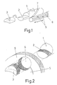
- Fig. 1 is a schematic diagram in perspective of the rotating action of a cylinder by means of the longitudinal displacement of an operating key, in accordance with the system forming the subject of the invention;
- Fig. 2 is an exploded diagram of the housing of the rotating cylinder and the complementary semi-cylindrical part in respect to the two concentric bodies between which blocking is brought about;
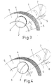
- Figs. 3 and 4 show details of the above-mentioned assembly of the rotating cylinder which can be operated by key and the concentric bodies which can be connected with the fixed and mobile parts of the lock, in the respective positions of unblocked and blocked between the above-mentioned concentric bodies;
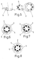
- Fig. 5 is an exploded diagram in perspective of a lock cylinder assembly with six blocking cylinders, only one of the cylinders having been illustrated;
- Figs. 6, 7 and 8 represent the schematic cross-section of a lock cylinder with six cylinders, in the unblocked positions of the rotating concentric bodies between the said bodies, and in a position in which one of the cylinders enclosed between the above-mentioned bodies causes blocking amongst the same, respectively;
- Fig. 9 corresponds to the schematic view of a longitudinal section of the above-mentioned lock cylinder with six cylinders.
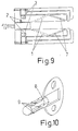
- Fig. 10 is a perspective of the corresponding key for the said lock cylinder with six cylinders;
- Fig. 11 is a schematic frontal view of a lock cylinder fitted with anassembly of eighteen cylinders divided into two groups of six and twelve respectively;
- Fig. 12 is an exploded diagram in perspective of the said lock cylinder with eighteen cylinders;
- Fig. 13 is the view of a transverse section of the said lock cylinder with eighteen cylinders, showing the area of blocking and unblocking of the respective concentric bodies;
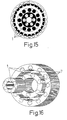
- Fig. 14 is a detail corresponding to a partial frontal schematic diagram of a lock cylinder with forty-two cylinders divided into three groups of six, twelve and twenty-four respectively;
- Fig. 15 is the view of a transverse section of the said with lock cylinder forty-two cylinders, showing the area of blocking and unblocking of the respective concentric bodies;
- Fig. 16 is an exploded diagram in perspective of the concentric bodies of the said lock cylinder with forty-two cylinders;
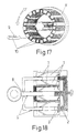
- Fig. 17 is a perspective of a key for the above-mentioned lock cylinder with forty-two cylinders, provided with interchangeable elements;
- Fig. 18 is a view of the longitudinal section of the said lock cylinder with forty-two cylinders, with the corresponding key partially introduced, and
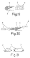
- Figs. 19, 20 and 21 show different variations in practical realisation of the cylinders which can be operated by key according to the system forming the subject of the invention;
-
- 1. - Cylinder
- 2. - blocking part
- 3. - Complementary blocking part
- 4. - Aperture
- 5. - External concentric body
- 6. - Internal concentric body
- 7. - Helical groove
- 8. - Operating key
- 9. - Projection
- 10. - Interchangeable parts
- 11. - Guide accessories
- The subject of the invention refers to a novel locking mechanism in which the elements for locking consist of a cylindrical rod (1), which has at its front end a first part (2), which is complemented by a corresponding independent part (3). The two complementary parts (2, 3) together form a cylinder, and the shear plane between them is arc shaped.
- The said end of cylinder (1), formed by the assembly of parts (2) and (3), is enclosed in a respective corresponding aperture (4), defined between each of concentric bodies (5) and (6), which are respectively connected with the fixed and moving parts of the corresponding lock, in such a way that, according to what can be seen from Figs. 3 and 4, when the assembly of parts (2) and (3) is arranged in such a way that its intermediate groove coincides with the division between bodies (5) and (6), rotation between the said bodies (5) and (6) and consequently operation of the lock becomes possible, whereas when this assembly of parts (2) and (3) are in any other rotating position, mobility between bodies (5) and (6) is blocked and operation of the lock is consequently blocked.
- Cylinder (1) is provided to that effect with a helical groove (7) defined along the same, such that the corresponding key (8) for operation of the lock is provided, in the corresponding correlating area of coincidence with the above-mentioned cylinder (1), with a projection (9) which is capable of being fitted by sliding into the above-mentioned groove (7).
- In this way, when key (8) is introduced into the lock cylinder, its own longitudinal displacement on introduction makes cylinder (1) rotate, with the effect that if the location of projection (9) over key (8) is sufficient for rotation of cylinder (1) to be effected precisely, which makes it locate itself at the assembly of semi-cylindrical parts (2) and (3) with their intermediate groove coinciding with the two bodies (5) and (6), the said introduction of key (8) brings about unblocking for the easy operation of the lock cylinder to which it is applied; so when the key itself (8) is withdrawn the positioning for the initial blocking occurs again.
- With such a realisation and operation, the number of possibilities of variations of the state of cylinder (1) in each case becomes great, since according to the longitudinal position in which projection (9) on key (8) is found, the rotation which is achieved by means of the introduction of the latter is different, and this enables a large number of different combinations to be obtained, varying this positioning of projection (9) on key (8) and the angular location of the assembly of parts (2) and (3) with respect to groove (7) of cylinder (1), so that when key (8) is introduced it determines the position of unblocking of concentric bodies (5) and (6) with respect to each other.
- Based on the said fundamental principal, the practical realisation of the assembly of a lock cylinder in accordance with this system can consist of two simple concentric bodies (5) and (6) and the inclusion of a set of multiple cylinders (1) for blocking and unblocking with respect to each other, in conformity with the views in Figs. 5 to 9, in such a way that the position of unblocking has to be accomplished with all the sets of parts (2) and (3) corresponding to the different cylinders (1), as can be seen in Fig. 6, so that rotation between concentric bodies (5) and (6) is achievable, as can be seen in Fig. 7; as long as any of the assemblies of parts (2) and (3) are not in the correct position, as can be seen in Fig. 8, blocking of bodies (5) and (6) with respect to each other will be established.
- Under the said conditions it is clear that all the assemblies of parts (2) and (3) have to be operated simultaneously to bring about unblocking, and for this a key (8) is provided, as shown in Fig. 10, provided with as many projections (9) as the lock cylinder contains cylinders (1) and situated adequately for each one of them to operate on one of the cylinders (1) of the lock cylinder, as well as positioned longitudinally in a precise way such that by means of them the respective cylinders (1) are positioned in the correct position for unblocking bodies (5) and (6) when the key is introduced into the lock cylinder.
- This in turn brings about a possibility of practically limitless combinations of key (8), with the additional peculiarity that it is necessary to know the precise position of introduction of the latter for the rotating operation to be carried out, given that only one of the six possible positions of introduction is effective.
- Underlying this aspect of multiple combinations which confer a greater level of security, the realisation of the lock cylinder can be carried out with a larger number of cylinders (1), such as for example with a total set of 18 cylinders (1) distributed in two concentric groups of 6 and 12 respectively, as shown in Figs. 11 to 13, in which case logically a tubular key (8) would be required with interior and exterior projections (9) to operate on all the cylinders (1).
- Even more complexity can be included, based on multiple associated lock cylinders, such as for example an assembly with a central lock cylinder with six cylinders (1), forming an integral part of a larger lock cylinder with two concentric groups of twelve and twenty-four cylinders (1) respectively, such as is the case in Figs. 14 to 16, in which case a total of forty-two blocking cylinders would result, with which clearly so complex a combination would be obtained that the security of inviolability would be practically total.
- In such a case the realisation of the corresponding key (8) would be as shown in Fig. 17, that is to say with a central nucleus and a tubular rim both provided with projections (9) on their surfaces to operate the different cylinders (1), the said key (8) being able to be realised with interchangeable parts (10) for better process of manufacture and to give the user great security in the case of loss of the same.
- Moreover, the said key (8) for such a complex combination would consist of two independent parts in such a way that, as can be seen in Fig. 18, the central nucleus of the same would be the operating part for the rotating operation and the external rim would only be to position the corresponding cylinders (1) for unblocking, both parts being able to rotate with respect to each other when the lock cylinder is operated; this in turn gives a total guarantee of security, even including using the key, given that its many ways of introduction and withdrawal mean that only the proprietor, knowing the appropriate position, can use it correctly.
- In effect, in the case of the afore-mentioned lock cylinder with forty-two cylinders (1), the key (8) only operates rotation in one single position, but however its introduction can be carried out in seventy-two different positions (6) with respect to the central part and twelve with respect to the external rim); inasmuch as withdrawal can be carried out in six different positions (which correspond to the six positions of the central part), this gives such diverse possibilities that only that person who knows the effective position can use the key with efficacy.
- In any case, the blocking parts formed by the assemblies of parts (2) and (3) are totally inaccessible from outside, and even if the corresponding cylinders (1) were broken, blocking of concentric bodies (5) and (6) with respect to each other would continue, without the lock being able to be operated.
- The possibilities of realisation of lock cylinders with multiple cylinders (1) are however not limited to the examples described, since in the same way other different possibilities exist, as there could be, in addition to those already indicated, a lock cylinder with twelve cylinders (1) in one single circular group, a lock cylinder with twenty-four cylinders (1) also in one single circular group, a lock cylinder with thirty cylinders (1) distributed in two concentric groups of six and twenty-four respectively, a lock cylinder with thirty-six cylinders (1) distributed in two concentric groups of twelve and twenty-four respectively, as well as any other possible combination imaginable.
- In another case, the cylinders (1) to realise this system could be formed by one single part, the corresponding structure (2) for blocking being formed at its end, or consist of two complementary parts which can be connected together such as is shown in Fig. 21; the said cylinders (1) can also be hollow, as shown in Figs. 19 and 20, the corresponding key (8), being able in another case to include the internal and/or external parts for operating on the said cylinders (1), and be included in combination with complementary guide accessories (11).
- The invention thus provides a simple but effective locking mechanism.
Claims (1)
- A locking mechanism and key, comprising one or more blocking elements each consisting of two complementary parts (2,3) together forming a cylinder snugly located in a correspondingly cylindrically shaped aperture (4) defined partly in a cylindrical surface of the first (5), and partly in a cylindrical surface of the second (6) of two concentric bodies (5,6) forming lock parts, which are lockable together, one of the complementary parts (2,3) being adapted to be operatively coupled to a key (8) to permit rotation of the two complementary parts (2,3), whereby the two complementary parts (2,3) can be rotated between a position in which they prevent movement of the two lock parts (5,6) and a position in which the arc shaped shear planes between the complementary parts (2,3) of all blocking elements coincide with said cylindrical surfaces of the two concentric bodies (5,6) thereby permitting their relative movement, characterised in that one of the complementary parts (2) of each blocking element is integral with an axially stationary generally cylindrical rotatable member (1) formed in its cylindrical surface with a helical groove (7), and in that the key (8) is formed with a projection (9) adapted to slide in said groove (7) such that when the key (8) is introduced the longitudinal displacement of the key (8) results in rotation of the rotatable member, and the locking mechanism being free from springs such that the positioning of the blocking elements is achieved by the movement of the key only.
Applications Claiming Priority (2)
| Application Number | Priority Date | Filing Date | Title |
|---|---|---|---|
| ES9102807A ES2058000B1 (en) | 1991-12-18 | 1991-12-18 | MECHANICAL LOCKING SYSTEM FOR LOCK BULBS AND THE LIKE. |
| ES9102807 | 1991-12-18 |
Publications (2)
| Publication Number | Publication Date |
|---|---|
| EP0547883A1 EP0547883A1 (en) | 1993-06-23 |
| EP0547883B1 true EP0547883B1 (en) | 1997-02-19 |
Family
ID=8274519
Family Applications (1)
| Application Number | Title | Priority Date | Filing Date |
|---|---|---|---|
| EP19920311489 Expired - Lifetime EP0547883B1 (en) | 1991-12-18 | 1992-12-16 | Cylinder lock with twisting tumblers |
Country Status (6)
| Country | Link |
|---|---|
| US (1) | US5351514A (en) |
| EP (1) | EP0547883B1 (en) |
| JP (1) | JP2794370B2 (en) |
| CA (1) | CA2085450A1 (en) |
| DE (1) | DE69217543T2 (en) |
| ES (1) | ES2058000B1 (en) |
Families Citing this family (7)
| Publication number | Priority date | Publication date | Assignee | Title |
|---|---|---|---|---|
| IT1302951B1 (en) * | 1998-12-28 | 2000-10-10 | Stefano Ficco | THREE-DIMENSIONAL KEY SECURITY LOCK WITH ORIENTED PINS. |
| JP4566991B2 (en) * | 2003-06-16 | 2010-10-20 | カムウェア、ホールディングス、プロプライエタリ、リミテッド | Rotary lock and key |
| NL1026291C2 (en) * | 2004-05-28 | 2005-11-30 | Alcumbrella Holding B V | Security locking system. |
| EP1635012A3 (en) * | 2004-09-01 | 2009-06-17 | Alpha Corporation | Cylinder lock device |
| US20090293563A1 (en) * | 2008-05-28 | 2009-12-03 | Bing-Huei Jeng | Lock with multiply circled cylinder |
| US8763435B2 (en) * | 2009-09-02 | 2014-07-01 | Camlock Systems Limited | Locking device |
| US20110192202A1 (en) * | 2010-02-09 | 2011-08-11 | Li-Jen Chang | Tubular lock safety structure |
Family Cites Families (16)
| Publication number | Priority date | Publication date | Assignee | Title |
|---|---|---|---|---|
| DE264352C (en) * | ||||
| US1067017A (en) * | 1912-11-16 | 1913-07-08 | Anton Frederiksen | Safety-lock. |
| US1154499A (en) * | 1914-09-02 | 1915-09-21 | John A Fischer | Lock. |
| US1589256A (en) * | 1922-03-13 | 1926-06-15 | Spruth Hans | Lock |
| GB421550A (en) * | 1933-06-21 | 1934-12-24 | Thomas Dudson | Improvements in and relating to locks and the like |
| US2060978A (en) * | 1934-04-23 | 1936-11-17 | Marshall William Deutsch | Adjustable tumbler lock |
| US2098249A (en) * | 1935-09-18 | 1937-11-09 | Kistner Lock And Appliance Com | Universal bolt lock |
| FR2212844A5 (en) * | 1972-12-29 | 1974-07-26 | Frank Roger | |
| DE2806072A1 (en) * | 1978-02-14 | 1979-08-16 | Perkut B R | Key and combination lock with axial tumbler pins - have additional transversely offset stop faces to activate different pins |
| GB2073302B (en) * | 1980-04-02 | 1984-03-14 | Multikey Ltd | Revolving cylinder locks |
| US4541260A (en) * | 1980-05-07 | 1985-09-17 | Edward Rubinstein | Guard plate and alarm |
| FR2488315A1 (en) * | 1980-08-05 | 1982-02-12 | Fichet Bauche | PUMP OR POCKET LOCK |
| US4534195A (en) * | 1982-02-19 | 1985-08-13 | Gretag Aktiengesellschaft | Mechanical lock having a variable key |
| EP0190916B1 (en) * | 1985-02-05 | 1991-03-20 | Titon Hardware Limited | Latch operating means |
| US4934164A (en) * | 1989-06-12 | 1990-06-19 | Shew Ming Chwan | Cylinder lock |
| US4996856A (en) * | 1990-04-16 | 1991-03-05 | Lin Peir Kuen | Structure of cylinder lock |
-
1991
- 1991-12-18 ES ES9102807A patent/ES2058000B1/en not_active Expired - Lifetime
-
1992
- 1992-12-15 CA CA 2085450 patent/CA2085450A1/en not_active Abandoned
- 1992-12-16 EP EP19920311489 patent/EP0547883B1/en not_active Expired - Lifetime
- 1992-12-16 DE DE1992617543 patent/DE69217543T2/en not_active Expired - Fee Related
- 1992-12-16 US US07/991,255 patent/US5351514A/en not_active Expired - Fee Related
- 1992-12-18 JP JP35583592A patent/JP2794370B2/en not_active Expired - Lifetime
Also Published As
| Publication number | Publication date |
|---|---|
| EP0547883A1 (en) | 1993-06-23 |
| JP2794370B2 (en) | 1998-09-03 |
| JPH06207483A (en) | 1994-07-26 |
| DE69217543D1 (en) | 1997-03-27 |
| ES2058000A2 (en) | 1994-10-16 |
| CA2085450A1 (en) | 1993-06-19 |
| ES2058000R (en) | 1996-03-01 |
| ES2058000B1 (en) | 1996-09-01 |
| US5351514A (en) | 1994-10-04 |
| DE69217543T2 (en) | 1997-07-24 |
Similar Documents
| Publication | Publication Date | Title |
|---|---|---|
| US4103526A (en) | Pin tumbler lock | |
| US4424693A (en) | Key-removable lock core | |
| CA1161656A (en) | Resettable lock assembly | |
| US5490405A (en) | Cylinder lock--key--combination | |
| CA2439151C (en) | High security cylinder lock and key | |
| US5421179A (en) | Cylinder lock provided with an exchangeable lock-cylinder | |
| JPS62156483A (en) | Cylinder lock with exchangable key | |
| PL192598B1 (en) | Combination: cylinder lock & key | |
| EP1019601A1 (en) | Cylinder lock | |
| AU2002245512A1 (en) | High security cylinder lock and key | |
| EP0547883B1 (en) | Cylinder lock with twisting tumblers | |
| US20230366242A1 (en) | Padlock basic assembly kit and padlock system | |
| US4866964A (en) | Removable core lock | |
| US4393672A (en) | Cylinder lock and key assembly | |
| JPH045114B2 (en) | ||
| US20190106905A1 (en) | Cylinder lock core for a cylinder lock unit | |
| US4838060A (en) | Tubular key and corresponding lock housing key entry construction | |
| US2807158A (en) | Multiple shear line lock with breech lock assembly means | |
| GB2073302A (en) | Revolving cylinder locks | |
| US1819853A (en) | Key operated combination lock | |
| US3868838A (en) | Cylindrical lock combination changer | |
| EP0162158A1 (en) | Cylinder lock and key | |
| US4458513A (en) | Lock and key set and key therefor | |
| EP2593622B1 (en) | An arrangement for a lock | |
| GB2217771A (en) | A manually rearrangable permutation lock set |
Legal Events
| Date | Code | Title | Description |
|---|---|---|---|
| PUAI | Public reference made under article 153(3) epc to a published international application that has entered the european phase |
Free format text: ORIGINAL CODE: 0009012 |
|
| AK | Designated contracting states |
Kind code of ref document: A1 Designated state(s): BE CH DE FR GB IT LI SE |
|
| 17P | Request for examination filed |
Effective date: 19931005 |
|
| 17Q | First examination report despatched |
Effective date: 19931125 |
|
| GRAG | Despatch of communication of intention to grant |
Free format text: ORIGINAL CODE: EPIDOS AGRA |
|
| GRAH | Despatch of communication of intention to grant a patent |
Free format text: ORIGINAL CODE: EPIDOS IGRA |
|
| GRAH | Despatch of communication of intention to grant a patent |
Free format text: ORIGINAL CODE: EPIDOS IGRA |
|
| GRAA | (expected) grant |
Free format text: ORIGINAL CODE: 0009210 |
|
| AK | Designated contracting states |
Kind code of ref document: B1 Designated state(s): BE CH DE FR GB IT LI SE |
|
| REG | Reference to a national code |
Ref country code: CH Ref legal event code: EP |
|
| REF | Corresponds to: |
Ref document number: 69217543 Country of ref document: DE Date of ref document: 19970327 |
|
| REG | Reference to a national code |
Ref country code: CH Ref legal event code: NV Representative=s name: KELLER & PARTNER PATENTANWAELTE AG |
|
| ITF | It: translation for a ep patent filed |
Owner name: 0508;10RMFFIAMMENGHI - DOMENIGHETTI |
|
| ET | Fr: translation filed | ||
| PGFP | Annual fee paid to national office [announced via postgrant information from national office to epo] |
Ref country code: GB Payment date: 19971201 Year of fee payment: 6 |
|
| PGFP | Annual fee paid to national office [announced via postgrant information from national office to epo] |
Ref country code: SE Payment date: 19971203 Year of fee payment: 6 |
|
| PGFP | Annual fee paid to national office [announced via postgrant information from national office to epo] |
Ref country code: BE Payment date: 19971212 Year of fee payment: 6 |
|
| PGFP | Annual fee paid to national office [announced via postgrant information from national office to epo] |
Ref country code: DE Payment date: 19971222 Year of fee payment: 6 |
|
| PGFP | Annual fee paid to national office [announced via postgrant information from national office to epo] |
Ref country code: FR Payment date: 19971224 Year of fee payment: 6 |
|
| PLBE | No opposition filed within time limit |
Free format text: ORIGINAL CODE: 0009261 |
|
| STAA | Information on the status of an ep patent application or granted ep patent |
Free format text: STATUS: NO OPPOSITION FILED WITHIN TIME LIMIT |
|
| PGFP | Annual fee paid to national office [announced via postgrant information from national office to epo] |
Ref country code: CH Payment date: 19971230 Year of fee payment: 6 |
|
| 26N | No opposition filed | ||
| PG25 | Lapsed in a contracting state [announced via postgrant information from national office to epo] |
Ref country code: GB Free format text: LAPSE BECAUSE OF NON-PAYMENT OF DUE FEES Effective date: 19981216 |
|
| PG25 | Lapsed in a contracting state [announced via postgrant information from national office to epo] |
Ref country code: SE Free format text: LAPSE BECAUSE OF NON-PAYMENT OF DUE FEES Effective date: 19981217 |
|
| PG25 | Lapsed in a contracting state [announced via postgrant information from national office to epo] |
Ref country code: LI Free format text: LAPSE BECAUSE OF NON-PAYMENT OF DUE FEES Effective date: 19981231 Ref country code: CH Free format text: LAPSE BECAUSE OF NON-PAYMENT OF DUE FEES Effective date: 19981231 Ref country code: BE Free format text: LAPSE BECAUSE OF NON-PAYMENT OF DUE FEES Effective date: 19981231 |
|
| BERE | Be: lapsed |
Owner name: REY RECIO ALBERTO Effective date: 19981231 |
|
| GBPC | Gb: european patent ceased through non-payment of renewal fee |
Effective date: 19981216 |
|
| REG | Reference to a national code |
Ref country code: CH Ref legal event code: PL |
|
| PG25 | Lapsed in a contracting state [announced via postgrant information from national office to epo] |
Ref country code: FR Free format text: LAPSE BECAUSE OF NON-PAYMENT OF DUE FEES Effective date: 19990831 |
|
| REG | Reference to a national code |
Ref country code: FR Ref legal event code: ST |
|
| PG25 | Lapsed in a contracting state [announced via postgrant information from national office to epo] |
Ref country code: DE Free format text: LAPSE BECAUSE OF NON-PAYMENT OF DUE FEES Effective date: 19991001 |
|
| PG25 | Lapsed in a contracting state [announced via postgrant information from national office to epo] |
Ref country code: IT Free format text: LAPSE BECAUSE OF NON-PAYMENT OF DUE FEES;WARNING: LAPSES OF ITALIAN PATENTS WITH EFFECTIVE DATE BEFORE 2007 MAY HAVE OCCURRED AT ANY TIME BEFORE 2007. THE CORRECT EFFECTIVE DATE MAY BE DIFFERENT FROM THE ONE RECORDED. Effective date: 20051216 |