EP0547820B1 - A magnetic recording disk having an improved protective overcoat - Google Patents
A magnetic recording disk having an improved protective overcoat Download PDFInfo
- Publication number
- EP0547820B1 EP0547820B1 EP92311134A EP92311134A EP0547820B1 EP 0547820 B1 EP0547820 B1 EP 0547820B1 EP 92311134 A EP92311134 A EP 92311134A EP 92311134 A EP92311134 A EP 92311134A EP 0547820 B1 EP0547820 B1 EP 0547820B1
- Authority
- EP
- European Patent Office
- Prior art keywords
- disk
- overcoat
- nitrogen
- approximately
- carbon
- Prior art date
- Legal status (The legal status is an assumption and is not a legal conclusion. Google has not performed a legal analysis and makes no representation as to the accuracy of the status listed.)
- Expired - Lifetime
Links
Images

Classifications
-
- G—PHYSICS
- G11—INFORMATION STORAGE
- G11B—INFORMATION STORAGE BASED ON RELATIVE MOVEMENT BETWEEN RECORD CARRIER AND TRANSDUCER
- G11B5/00—Recording by magnetisation or demagnetisation of a record carrier; Reproducing by magnetic means; Record carriers therefor
- G11B5/62—Record carriers characterised by the selection of the material
- G11B5/72—Protective coatings, e.g. anti-static or antifriction
- G11B5/727—Inorganic carbon protective coating, e.g. graphite, diamond like carbon or doped carbon
-
- G—PHYSICS
- G11—INFORMATION STORAGE
- G11B—INFORMATION STORAGE BASED ON RELATIVE MOVEMENT BETWEEN RECORD CARRIER AND TRANSDUCER
- G11B5/00—Recording by magnetisation or demagnetisation of a record carrier; Reproducing by magnetic means; Record carriers therefor
- G11B5/84—Processes or apparatus specially adapted for manufacturing record carriers
Definitions
- This invention relates to a thin film metal alloy magnetic recording disk having a protective carbon overcoat which contains nitrogen.
- each of the read/write transducers is supported on a carrier (or slider) which rides on a cushion or bearing of air above the surface of its associated disk when the disk is rotating at its operating speed.
- the slider is connected to a linear or rotary actuator by means of a relatively fragile suspension.
- a thin film metal alloy disk which typically comprises a substrate, such as an aluminium-magnesium (AlMg) alloy with a nickel-phosphorous (NiP) surface coating, a cobalt-based alloy, such as a CoPt or CoNi alloy, sputter deposited as the magnetic layer on the substrate, and a protective overcoat, such as a sputter-deposited amorphous carbon film, formed on the magnetic layer.
- a substrate such as an aluminium-magnesium (AlMg) alloy with a nickel-phosphorous (NiP) surface coating
- a cobalt-based alloy such as a CoPt or CoNi alloy
- sputter deposited as the magnetic layer on the substrate and a protective overcoat, such as a sputter-deposited amorphous carbon film, formed on the magnetic layer.
- thin film disks may also include a sputter-deposited underlayer, such as a layer of chromium (Cr), chromium-vanadium (CrV) or tungsten (W), between the substrate and the magnetic layer and a sputter deposited adhesion layer, such as a Cr, W or titanium (Ti) layer, between the magnetic layer and the protective overcoat.
- a sputter-deposited underlayer such as a layer of chromium (Cr), chromium-vanadium (CrV) or tungsten (W)
- Cr chromium-vanadium
- W tungsten
- DE-A-3 519 383 discloses a magnetic recording medium having a thin layer of magnetic material which is protected by a protective layer of carbon nitride having a thickness of between 20 and 150 nm (200 and 1500 Angstroms).
- Protective carbon overcoats for thin film metal alloy disks are well known. They are typically formed by sputter deposition from a graphite target, and are generally referred to merely as protective carbon overcoats, sputtered carbon overcoats, "diamondlike” carbon overcoats, amorphous carbon overcoats, or, in the case of those overcoats formed by sputter deposition in the presence of a hydrogen containing gas, hydrogenated carbon overcoats.
- 4,778,582 describes a protective hydrogenated carbon overcoat formed by sputtering a graphite target in the presence of argon and hydrogen (H 2 ).
- the incorporation of hydrogen into amorphous carbon films increases the hardness and electrical resistivity of the films.
- US 4880687 and US 5069967 disclose a magnetic recording medium having a plasma-polymerised film and a fluorine topcoat, preferably with a carbon film disposed between the two.
- the plasma-polymerised film has a thickness from 0.3-30 nm, and comprises carbon and hydrogen, plus optionally nitrogen, oxygen, silicon, sulphur, phosphorus or boron (or mixtures thereof).
- US 4804590 discloses an abrasion resistant magnetic recording member having a carbonaceous protective film comprising a soft upper layer and a harder lower layer.
- the lower layer is formed of sputtered carbon or plasma enhanced chemical vapour deposition (PCVD) carbon
- the upper layer is formed by PCVD and contains hydrogen and/or fluorine.
- PCVD plasma enhanced chemical vapour deposition
- One of the problems associated with protective disk overcoats is that, due to their inherent thickness required for the wear and corrosion resistance of the underlying magnetic layer, the spacing between the head and the magnetic layer is necessarily increased. Since the strength of the signal required to write data onto the magnetic layer with the write head and the strength of the signal read back from the magnetic layer by the read head are directly proportional to the spacing between the head and the magnetic layer, it is desirable to minimise this spacing.
- the minimum thickness of protective amorphous carbon or amorphous hydrogenated carbon overcoats in commercially available magnetic recording disks is in the range of 20-25nm (200-250 ⁇ ). However, it has been found experimentally that the minimum film thickness before loss of protection occurs is in the range of approximately 12.5nm (125 ⁇ ).
- a thin film magnetic recording disk comprising a substrate, a magnetic alloy layer formed over the substrate, a protective overcoat comprising carbon, hydrogen and nitrogen, the carbon in the overcoat being in essentially amorphous form, and characterised by the overcoat being formed directly on the magnetic layer and having a thickness of less than 20nm (200 Angstroms).
- a thin film metal alloy magnetic recording disk having a protective carbon overcoat which contains nitrogen.
- the nitrogen present in the overcoat substantially reduces the film stress. Due to the low stress of the film there is significantly less likelihood that the overcoat will delaminate, buckle, or otherwise wear away from the underlying magnetic layer during operation of the disk file. This allows for significantly reduced overcoat thickness, thus reducing the head-disk spacing in the disk file.
- the overcoat even though significantly thinner than prior art carbon overcoats, exhibits better wear and corrosion resistance than carbon overcoats without nitrogen.
- the overcoat is a hydrogenated carbon film, the presence of the nitrogen increases the hardness of the film if present within a range dependent on the amount of hydrogen added to the film.
- the effect of nitrogen on the properties of amorphous hydrogenated carbon films used as protective disk overcoats was observed for overcoats made by both plasma enhanced chemical vapour deposition (CVD) and sputter deposition.
- the nitrogen-containing hydrogenated carbon films were formed on thin film disks and on single crystal semiconductor grade silicon wafers and compared with comparable films formed without nitrogen.
- the thin film metal alloy magnetic disks onto which the overcoats were formed comprised an AlMg substrate with a NiP surface coating and a CoPtCr magnetic layer of approximately 30nm (300A) thickness.
- the deposition pressure was maintained at 0.8Pa (6 mTorr) and deposition of the hydrogenated carbon film was accomplished by introducing hydrocarbon gas (cyclo-pentane) into the plasma.
- hydrocarbon gas cyclo-pentane
- Other hydrocarbon gases e.g. methane, ethylene or benzene, could also be used.
- the partial pressure of the hydrocarbon gas was held at 0.07Pa (0.5 mTorr).
- the plasma was ignited using low frequency RF (300 KHz) at 400 watts.
- the substrates were biased at -300 volts DC. It has been determined experimentally that a substrate bias, in the range of approximately -200 to -600 volts DC, is important to achieve a film of sufficient hardness.
- a carrier gas with a one-to-one ratio of argon and nitrogen was utilised for the deposition of the nitrogen-containing hydrogenated carbon films.
- Deposition time was nominally 45 seconds.
- Total overcoat thickness was nominally 7.5nm (75 ⁇ ).
- sputtering was accomplished by DC magnetron by use of a high-purity hard pressed graphite target using a DC source at 1.5 kilowatts.
- the substrates were biased at 650 watts with a low frequency power supply operating at 300 KHz. While the addition of substrate bias has been found experimentally to improve the wear resistance of the films, it is possible to make adequate films without the use of substrate bias.
- the carrier gas was argon plus 4 percent hydrogen for the disk overcoats formed without nitrogen, and argon with 4 percent hydrogen plus 50 percent nitrogen for the disk overcoats with nitrogen. Measurements made by RBS demonstrated that the nitrogen-containing hydrogenated carbon films contained about 14 at.% nitrogen and approximately 11 at.% hydrogen. The films made without added nitrogen contained approximately 20 at.% hydrogen and no detectable nitrogen. Films with varying amounts of hydrogen and nitrogen were made by varying the amount of hydrogen and nitrogen gases introduced into the sputtering chamber.
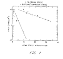
- Fig. 1 This unexpected reduction in film stress as a function of the addition of nitrogen is illustrated graphically in Fig. 1 for films formed on silicon wafers by both processes.
- the internal stress of the films was measured with a wafer deflection gauge made by Ionic Systems.
- the films used for the stress measurement were formed to a nominal thickness of 200 nm (2000 ⁇ ) on 7.6 cm (3 inch) diameter silicon wafers .
- the wafers were then placed in the gauge with the film side facing away from the light sensor.
- the principle behind the stress measurement is that when the film is formed on the silicon wafer it will introduce an amount of deflection or bow to the wafer. The accurate measurement of this bow allows computation of the film's stress.
- the stress of the film as.a protective disk overcoat is directly related to its ability to adhere to the underlying magnetic layer on the thin film disk. It is desirable that the overcoat exhibit zero stress, which would indicate its maximum adhesion to the magnetic layer, and thus a low probability that it would delaminate, buckle, or otherwise wear away from the magnetic layer during operation of the disk file.
- the curve for the overcoat with 5 at.% hydrogen indicates that the overcoat is made harder if nitrogen is present in an amount up to approximately 25 CTRL at.%.
- the data illustrated in Fig. 2 thus suggests some type of synergistic effect between the hydrogen and nitrogen in the overcoats.
- the addition of nitrogen to amorphous hydrogenated carbon films enables protective overcoats to be formed for thin film disks to a thickness significantly below both the previously achievable commercially available film thickness of 20 nm (200 ⁇ ) and the experimentally observed 12.5 nm (125 ⁇ ) thickness. This is achievable as a result of the discovery of the significant film stress reduction caused by the addition of nitrogen, and the discovery that such thinner films provide greater wear resistance, corrosion resistance, and hardness than conventional hydrogenated carbon films.
Landscapes
- Chemical & Material Sciences (AREA)
- Inorganic Chemistry (AREA)
- Magnetic Record Carriers (AREA)
- Manufacturing Of Magnetic Record Carriers (AREA)
Description
Claims (13)
- A thin film magnetic recording disk comprising a substrate, a magnetic alloy layer formed over the substrate, a protective overcoat comprising carbon, hydrogen and nitrogen, the carbon in the overcoat being in essentially amorphous form, and characterised by the overcoat being formed directly on the magnetic layer and having a thickness of less than 20nm (200 Angstroms).
- A disk as claimed in claim 1 wherein the magnetic alloy is cobalt based.
- A disk as claimed in claim 1 or 2, wherein the overcoat contains hydrogen in an amount between approximately 5 and 25 atomic percent.
- A disk as claimed in claim 3 wherein the overcoat contains nitrogen in an amount less than approximately 25 atomic percent.
- A disk as claimed in any preceding claim wherein hydrogen is present in an amount less than approximately 25 percent and the nitrogen is present in an amount less than approximately 15 atomic percent.
- A disk as claimed in claim 1 or 2, wherein the hydrogen is present in an amount less than approximately 5 atomic percent and the nitrogen is present in an amount less than approximately 25 percent.
- A disk as claimed in any preceding claim, wherein the overcoat is sputter deposited.
- A disk as claimed in any preceding claim, wherein the overcoat is deposited by chemical vapour deposition.
- A disk as claimed in any preceding claim, wherein the thickness of the overcoat is less than 12.5nm (125 Angstroms).
- A disk as claimed in claim 9, wherein the thickness of the overcoat is approximately 7.5nm (75 Angstroms).
- A disk as claimed in any preceding claim, further including a layer of lubricant on top of the overcoat.
- A disk as claimed in any preceding claim, wherein the substrate is single crystal silicon.
- A disk as claimed in any of claims 1 to 12, wherein the substrate is an aluminium alloy disk having an NiP surface coating.
Priority Applications (1)
| Application Number | Priority Date | Filing Date | Title |
|---|---|---|---|
| EP98101435A EP0844603A1 (en) | 1991-12-16 | 1992-12-07 | A magnetic recording disk having an improved protective overcoat |
Applications Claiming Priority (2)
| Application Number | Priority Date | Filing Date | Title |
|---|---|---|---|
| US80833891A | 1991-12-16 | 1991-12-16 | |
| US808338 | 1991-12-16 |
Related Child Applications (1)
| Application Number | Title | Priority Date | Filing Date |
|---|---|---|---|
| EP98101435A Division EP0844603A1 (en) | 1991-12-16 | 1992-12-07 | A magnetic recording disk having an improved protective overcoat |
Publications (2)
| Publication Number | Publication Date |
|---|---|
| EP0547820A1 EP0547820A1 (en) | 1993-06-23 |
| EP0547820B1 true EP0547820B1 (en) | 1998-09-16 |
Family
ID=25198504
Family Applications (2)
| Application Number | Title | Priority Date | Filing Date |
|---|---|---|---|
| EP98101435A Withdrawn EP0844603A1 (en) | 1991-12-16 | 1992-12-07 | A magnetic recording disk having an improved protective overcoat |
| EP92311134A Expired - Lifetime EP0547820B1 (en) | 1991-12-16 | 1992-12-07 | A magnetic recording disk having an improved protective overcoat |
Family Applications Before (1)
| Application Number | Title | Priority Date | Filing Date |
|---|---|---|---|
| EP98101435A Withdrawn EP0844603A1 (en) | 1991-12-16 | 1992-12-07 | A magnetic recording disk having an improved protective overcoat |
Country Status (7)
| Country | Link |
|---|---|
| EP (2) | EP0844603A1 (en) |
| JP (1) | JPH05225556A (en) |
| KR (1) | KR960011788B1 (en) |
| BR (1) | BR9204634A (en) |
| DE (1) | DE69227013T2 (en) |
| SG (1) | SG47386A1 (en) |
| TW (1) | TW210391B (en) |
Families Citing this family (7)
| Publication number | Priority date | Publication date | Assignee | Title |
|---|---|---|---|---|
| US5521781A (en) * | 1992-10-30 | 1996-05-28 | Shin-Etsu Chemical Co., Ltd. | Substrate for magnetic recording medium |
| JPH06333231A (en) * | 1993-05-21 | 1994-12-02 | Nec Corp | Magnetic recording medium and its production |
| EP0637821B1 (en) * | 1993-07-31 | 1999-05-06 | Shin-Etsu Chemical Co., Ltd. | Method for the preparation of a substrate for magnetic recording medium |
| JP3058066B2 (en) * | 1995-11-06 | 2000-07-04 | 富士電機株式会社 | Magnetic recording medium and method of manufacturing the same |
| US6403194B1 (en) | 1998-09-03 | 2002-06-11 | Hitachi, Ltd. | Magnetic recording medium, process for producing same and magnetic disc apparatus |
| US6565719B1 (en) | 2000-06-27 | 2003-05-20 | Komag, Inc. | Magnetic disk comprising a first carbon overcoat having a high SP3 content and a second carbon overcoat having a low SP3 content |
| JP2010250929A (en) | 2009-03-27 | 2010-11-04 | Wd Media Singapore Pte Ltd | Lubricant compound for magnetic disk, magnetic disk and manufacturing method thereof |
Family Cites Families (5)
| Publication number | Priority date | Publication date | Assignee | Title |
|---|---|---|---|---|
| JPS60253021A (en) * | 1984-05-30 | 1985-12-13 | Victor Co Of Japan Ltd | Magnetic recording medium |
| DE3578017D1 (en) * | 1985-11-19 | 1990-07-05 | Ibm | METHOD AND DEVICE FOR REGULATING THE HEIGHT OF THE HEAD IN A MAGNETIC MEMORY. |
| JPS6486312A (en) * | 1986-05-09 | 1989-03-31 | Tdk Corp | Magnetic recording medium |
| US4880687A (en) * | 1986-05-09 | 1989-11-14 | Tdk Corporation | Magnetic recording medium |
| US5285343A (en) * | 1989-10-13 | 1994-02-08 | Hitachi, Ltd. | Magnetic disk with surface protective layer having convex portions and magnetic disk apparatus including such a magnetic disk |
-
1992
- 1992-11-16 JP JP4305108A patent/JPH05225556A/en active Pending
- 1992-11-17 KR KR1019920021539A patent/KR960011788B1/en not_active Expired - Fee Related
- 1992-12-01 BR BR9204634A patent/BR9204634A/en not_active Application Discontinuation
- 1992-12-07 DE DE69227013T patent/DE69227013T2/en not_active Expired - Fee Related
- 1992-12-07 EP EP98101435A patent/EP0844603A1/en not_active Withdrawn
- 1992-12-07 EP EP92311134A patent/EP0547820B1/en not_active Expired - Lifetime
- 1992-12-07 SG SG1996000407A patent/SG47386A1/en unknown
-
1993
- 1993-01-11 TW TW082100122A patent/TW210391B/zh active
Also Published As
| Publication number | Publication date |
|---|---|
| DE69227013D1 (en) | 1998-10-22 |
| EP0844603A1 (en) | 1998-05-27 |
| KR960011788B1 (en) | 1996-08-30 |
| TW210391B (en) | 1993-08-01 |
| KR930014316A (en) | 1993-07-22 |
| EP0547820A1 (en) | 1993-06-23 |
| BR9204634A (en) | 1993-06-22 |
| DE69227013T2 (en) | 1999-06-02 |
| JPH05225556A (en) | 1993-09-03 |
| SG47386A1 (en) | 1998-04-17 |
Similar Documents
| Publication | Publication Date | Title |
|---|---|---|
| JP3157006B2 (en) | Carbon film forming method, magnetic memory structure, and magnetic disk manufacturing method | |
| US6146737A (en) | Magnetic recording medium having a nitrogen-containing barrier layer | |
| US6682807B2 (en) | Magnetic disk comprising a first carbon overcoat having a high SP3 content and a second carbon overcoat having a low SP3 content | |
| EP0221309B1 (en) | Metallic magnetic recording medium | |
| EP0293662B1 (en) | A process for making a thin film metal alloy magnetic recording disk with a hydrogenated carbon overcoat | |
| US5942317A (en) | Hydrogenated carbon thin films | |
| US4840844A (en) | Magnetic recording medium | |
| US4804590A (en) | Abrasion resistant magnetic recording member | |
| US5897931A (en) | Magnetic disk with boron carbide overcoat layer | |
| EP0844603A1 (en) | A magnetic recording disk having an improved protective overcoat | |
| US6238780B1 (en) | Magnetic recording medium comprising multilayered carbon-containing protective overcoats | |
| US6136421A (en) | Magneto-resistance recording media comprising multilayered protective overcoats | |
| US6537686B1 (en) | Magneto-resistance recording media comprising a silicon nitride corrosion barrier layer and a C-overcoat | |
| US6824836B1 (en) | Protection overcoat for recording media | |
| EP0026496B1 (en) | Magnetic recording disc and method for forming a protective overcoating thereon | |
| US5981018A (en) | Magnetic recording media used in a high-density hard disk drive | |
| JPH07161034A (en) | Magnetic recording medium | |
| US6764757B1 (en) | Recording medium with a lubricating layer having increased thermal stability | |
| US6517956B1 (en) | Magneto-resistance recording media comprising aluminum nitride corrosion barrier layer and a c-overcoat | |
| JP2535410B2 (en) | Magnetic recording medium and manufacturing method thereof | |
| JP2008276912A (en) | Vertical magnetic recording medium and its manufacturing method | |
| US6340521B1 (en) | Magnetic recording medium with protective barrier layer | |
| Novotny et al. | Tin oxide overcoats for thin film magnetic recording media | |
| EP1271483B1 (en) | Metallic thin film type magnetic recording medium and method of manufacturing thereof | |
| Chiba et al. | A highly durable structure of carbon protective layer |
Legal Events
| Date | Code | Title | Description |
|---|---|---|---|
| PUAI | Public reference made under article 153(3) epc to a published international application that has entered the european phase |
Free format text: ORIGINAL CODE: 0009012 |
|
| AK | Designated contracting states |
Kind code of ref document: A1 Designated state(s): DE FR GB |
|
| 17P | Request for examination filed |
Effective date: 19931021 |
|
| 17Q | First examination report despatched |
Effective date: 19950508 |
|
| GRAG | Despatch of communication of intention to grant |
Free format text: ORIGINAL CODE: EPIDOS AGRA |
|
| GRAG | Despatch of communication of intention to grant |
Free format text: ORIGINAL CODE: EPIDOS AGRA |
|
| GRAG | Despatch of communication of intention to grant |
Free format text: ORIGINAL CODE: EPIDOS AGRA |
|
| GRAH | Despatch of communication of intention to grant a patent |
Free format text: ORIGINAL CODE: EPIDOS IGRA |
|
| GRAH | Despatch of communication of intention to grant a patent |
Free format text: ORIGINAL CODE: EPIDOS IGRA |
|
| GRAA | (expected) grant |
Free format text: ORIGINAL CODE: 0009210 |
|
| AK | Designated contracting states |
Kind code of ref document: B1 Designated state(s): DE FR GB |
|
| REF | Corresponds to: |
Ref document number: 69227013 Country of ref document: DE Date of ref document: 19981022 |
|
| ET | Fr: translation filed | ||
| PLBE | No opposition filed within time limit |
Free format text: ORIGINAL CODE: 0009261 |
|
| 26N | No opposition filed | ||
| PGFP | Annual fee paid to national office [announced via postgrant information from national office to epo] |
Ref country code: GB Payment date: 20011210 Year of fee payment: 10 |
|
| PGFP | Annual fee paid to national office [announced via postgrant information from national office to epo] |
Ref country code: DE Payment date: 20011211 Year of fee payment: 10 |
|
| PGFP | Annual fee paid to national office [announced via postgrant information from national office to epo] |
Ref country code: FR Payment date: 20011218 Year of fee payment: 10 |
|
| REG | Reference to a national code |
Ref country code: GB Ref legal event code: IF02 |
|
| PG25 | Lapsed in a contracting state [announced via postgrant information from national office to epo] |
Ref country code: GB Free format text: LAPSE BECAUSE OF NON-PAYMENT OF DUE FEES Effective date: 20021207 |
|
| PG25 | Lapsed in a contracting state [announced via postgrant information from national office to epo] |
Ref country code: DE Free format text: LAPSE BECAUSE OF NON-PAYMENT OF DUE FEES Effective date: 20030701 |
|
| GBPC | Gb: european patent ceased through non-payment of renewal fee | ||
| PG25 | Lapsed in a contracting state [announced via postgrant information from national office to epo] |
Ref country code: FR Free format text: LAPSE BECAUSE OF NON-PAYMENT OF DUE FEES Effective date: 20030901 |
|
| REG | Reference to a national code |
Ref country code: FR Ref legal event code: ST |