EP0547348A2 - Electrophotographic color printer and method - Google Patents
Electrophotographic color printer and method Download PDFInfo
- Publication number
- EP0547348A2 EP0547348A2 EP92118744A EP92118744A EP0547348A2 EP 0547348 A2 EP0547348 A2 EP 0547348A2 EP 92118744 A EP92118744 A EP 92118744A EP 92118744 A EP92118744 A EP 92118744A EP 0547348 A2 EP0547348 A2 EP 0547348A2
- Authority
- EP
- European Patent Office
- Prior art keywords
- color
- photoconductive drum
- toners
- magenta
- cyan
- Prior art date
- Legal status (The legal status is an assumption and is not a legal conclusion. Google has not performed a legal analysis and makes no representation as to the accuracy of the status listed.)
- Granted
Links
Images

Classifications
-
- G—PHYSICS
- G03—PHOTOGRAPHY; CINEMATOGRAPHY; ANALOGOUS TECHNIQUES USING WAVES OTHER THAN OPTICAL WAVES; ELECTROGRAPHY; HOLOGRAPHY
- G03G—ELECTROGRAPHY; ELECTROPHOTOGRAPHY; MAGNETOGRAPHY
- G03G15/00—Apparatus for electrographic processes using a charge pattern
- G03G15/01—Apparatus for electrographic processes using a charge pattern for producing multicoloured copies
- G03G15/0105—Details of unit
- G03G15/0126—Details of unit using a solid developer
-
- G—PHYSICS
- G03—PHOTOGRAPHY; CINEMATOGRAPHY; ANALOGOUS TECHNIQUES USING WAVES OTHER THAN OPTICAL WAVES; ELECTROGRAPHY; HOLOGRAPHY
- G03G—ELECTROGRAPHY; ELECTROPHOTOGRAPHY; MAGNETOGRAPHY
- G03G15/00—Apparatus for electrographic processes using a charge pattern
- G03G15/01—Apparatus for electrographic processes using a charge pattern for producing multicoloured copies
- G03G15/0142—Structure of complete machines
- G03G15/0147—Structure of complete machines using a single reusable electrographic recording member
- G03G15/0152—Structure of complete machines using a single reusable electrographic recording member onto which the monocolour toner images are superposed before common transfer from the recording member
- G03G15/0163—Structure of complete machines using a single reusable electrographic recording member onto which the monocolour toner images are superposed before common transfer from the recording member primary transfer to the final recording medium
Abstract
Description
- This invention related generally to electrophotographic color printers, also known as laser printers, and more particularly to a projection type of electrophotographic color printer using stationary positioned developer rollers.
- In the field of electrophotographic color printing, it is known to move cyan, yellow, magenta, and black developer rollers into and out of contact with an adjacent photoconductive drum in order to provide the surface of the photoconductive drum with cyan, yellow, magenta, and black color toners. These color toners are selectively applied to the surface of the photoconductive drum and there developed to thus produce color images on the surface of the photoconductive drum which are subsequently transferred in series to an adjacent print medium.
- One disadvantage of these prior color development systems which move the developer rollers into and out of contact with the surface of the photoconductive drum is that either motor driven cams or the like are required to control the physical motion of the developer rollers or a rotating carousel is required to successively bring the cyan, magenta, yellow, and black rollers into contact with the photoconductive drum. In either case, there are attendant mechanical disadvantages associated with the mechanical precision and high cost required for imparting highly controlled motion to these developer rollers. Accordingly, it is the solution to the above problems to which the present invention is directed.
- The general purpose and principal object of the present invention is to provide a new and improved projection type of electrophotographic color printer which has been constructed in a novel manner to utilize stationary positioned development rollers adjacent to the surface of a photoconductive drum. In this manner, no mechanical motion other than rotational motion need be imparted to these rollers, and this approach overcomes the above described disadvantages associated with prior art carousel and cam driven developer rollers in a color printing system.
- Another object of this invention is to provide a new and improved electrophotographic color printer of the type described which is relatively straightforward and economical in construction, reliable in operation and requires a minimum of moving parts and maintenance.
- Another object of this invention is to provide a new and improved printer and method of the type described where the position and shape of the photoconductive drum is not critical, since each color plane will be deposited accurately relative to one another.
- To accomplish this purpose and objects, there is disclosed and claimed herein an improved electrophotographic color printer and method of operation which comprises, among other things, providing color toners of cyan, yellow magenta, and black adjacent to the surface of a photoconductive drum; providing cyan, yellow, magenta, and black development rollers at fixed locations between these color toners and the photoconductive surface of the drum and at a predetermined distance from the surface of the photoconductive drum; and selectively driving the development rollers with both AC and DC signals while simultaneously rotating these development rollers within adjacent color toner compartments to thereby selectively and electrostatically project the toners from the surfaces of the development rollers onto the adjacent surface of the photoconductive drum. Using this approach, the selectively projected color toners of cyan, yellow, magenta, and black are then developed in series on the surface of the photoconductive drum, which has been selectively discharged by the use of a laser light beam or an equivalent image development source. The developed images in each color plane are then transferred in series to the surface of a print medium which is passed between the surface of the photoconductive drum and an adjacent transfer roller.
- The above brief summary of the invention, together with its novel features and attendant advantages, will become better understood from the following description of a preferred embodiment of the invention shown schematically in the accompanying drawing.
- Figure 1 is a schematic cross section view of a color development system constructed in accordance with a preferred embodiment of the invention.
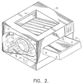
- Figure 2 is an abbreviated isometric view which shows how the development system of Figure 1 will be positioned and operated within the housing of a color laser printer.
- Referring now to Figure 1, the color printer development system shown therein is designated generally as 10 and includes a fixed position or non-rotating
carousel 12 having a plurality ofcolor toner compartments color toner compartments single developer roller openings tapered compartments - Each of the
developer rollers central axes separate voltage source voltage sources roller surface 48 of thephotoconductive drum 50. These voltage settings will therefore drive the negativelycharged toner photoconductive drum 50. Additionally, the AC voltage of about 200 Hertz and 1000 Vpp is also added to enhance image development as explained in more detail by Takahaski et al in an article entitled "Mechanism of Canon Toner Projection Development", Photographic Science and Engineering,Volume 26, No. 5, September/October 1982, incorporated herein by reference. - Each of the
developer rollers surface 48 of thephotoconductive drum 50 by a distance slightly greater than twice the thickness of the toner layers to be projected onto theouter surface 48 of thephotoconductive drum 50. The height of the toner on thedeveloper rollers doctor blades toner compartments developer rollers developer roller 22 and thephotoconductive drum 50, the color toner which has been developed on the photoconductor surface is not disturbed as it passes beneath the next developer station. Thus, this approach is applicable to the projection development systems used in Hewlett Packard's Laser Jet printers where the toner is projected across a gap by the use of externally applied electric fields. - Using this approach, the colored toners are magnetically and eletrostatically attracted to the surfaces of the
developer rollers compartments surface 48 of thephotoconductive drum 50 only upon the selective application of an AC and DC signal to a desired one of these developer rollers. In this manner, the individual colored toners may be selectively projected onto the surface of thephotoconductive drum 50 where latent images produced by abeam 52 of light from a laser source (not shown) are developed into color images. An example of such a projection type of development system is disclosed in the above-identified Takahaski et al article and developed by Canon of Japan. - The color development system shown in Figure 1 will also include rotatable toner stirring
blades K compartments developer rollers charging roller 56 for providing a desired level of electrostatic charge on the surface of thephotoconductive drum 50 and for providing the desired level of electrostatic attraction for the individually projected color toners. Theprojection system 10 in Figure 1 will further include atransfer roller 58 rotatably mounted about acentral axis 60 and positioned as shown immediately adjacent to thesurface 48 of thephotoconductive drum 50 at a location through which theprint medium 62 or other suitable intermediate transfer member (ITM-not shown) will pass. - Therefore, in operation, the
print medium 62 will traverse a 360° path for the transfer of each of the cyan, magenta, yellow, and black developed images in series from the surface of thephotoconductive drum 50 to themedium 62. Theprint medium 62 will be guided on each successive pass between thefuser rollers 90 and 92 shown in Figure 2 described below where the composite color image is fixed on the surface of theprint medium 62 before being finally passed into an output paper collection tray or bin using well known paper motion and control techniques. Suitable media control techniques for controlling paper motion during the above color printing process are disclosed in my above identified co-pending applications which are incorporated herein by reference. - Referring now to Figure 2, there is shown a color
electrophotographic printer housing 80 which includes aninput paper tray 82 and an outputpaper collection bin 84 of the type currently used, for example, in Hewlett Packard's LaserJet Printers. Thenear side wall 86 of the printer housing is shown with asection 88 thereof cut-away so that the general location of the color development system of Figure 1 therein can be seen in relation to the paper guide mechanisms used for controlling the paper motion. These paper guide mechanisms include, of course, the previously describedphotoconductive drum 50 which is mounted adjacent to thetransfer roller 58 and between which thepaper 62 passes four successive times as it receives color toner from the AC and DC operatedcolor projection rollers - The paper guide system shown in Figure 2 will further include a pair of
output fuser rollers 90 and 92 which are operative in a well known manner to serially fuse the cyan, yellow, magenta, and black color images into thepaper 62 on each of four successive passes of thepaper 62 along a 360° path, first around the interior surface of a first contoured paper guide member 94, then through a first pair of lowerpaper guide rollers paper guide rollers paper guide member 104. When thepaper 62 has made three successive 360° passes around this 360⁰ path, the media is caused to traverse over the surface of the upwardly facing paper deflection member 106 in the direction of arrow 108 and then out of thepaper exit port 110 at the far end of thepaper receiving bin 84. - Various modifications may be made in/to the above described embodiment without departing from the spirit and scope of this invention. The color development system shown in an abbreviated form and schematically in Figures 1 and 2 is intended to illustrate broad principles of color image development operation without being specifically limited to any particular hardware, design or to the use with only the subtractive colors of cyan, yellow, magenta, and black. Thus, for this reason, the preferred embodiment described herein has been illustrated in abbreviated schematic diagram form and is not limited to any particular constructional hardware, the selection and variations of which may be made by designers and engineers skilled in the art. Accordingly, many mechanical design variations in Figures 1 and 2 may be made by those skilled in the art without departing from the scope of the following appended claims.
Claims (6)
- A process for electrophotographic color printing which includes the steps of:a. providing color toners (29, 31, 33, 35) of cyan, yellow, magenta, and black,b. providing cyan, yellow, magenta, and black developer rollers (22, 24, 26, 28) at a fixed location between said toners (29, 31, 33, 35) and said surface (48) of said photoconductive drum (50) and at a predetermined distance from the surface of said photoconductive drum, andc. selectively driving said developer rollers (22, 24, 26, 28) with separate AC and DC signals (45, 47, 49, 51) while simultaneously rotating said developer rollers (22, 24, 26, 28) to attract charged color toners to the surface thereof to thereby selectively project said color toners (29, 31, 33, 35) onto the surface of said photoconductive drum (50) in preparation of color image development thereon.
- The process defined in claim 1 which also includes serially transferring developed color images from the surface of said photoconductive drum (50) to the surface of an adjacent print media (62) which passes between said drum (50) and a transfer roller (58).
- An electrophotographic color printer which includes:a. means for providing color toners (29, 31, 33, 35) of cyan, yellow, magenta, and black, andb. cyan, yellow, magenta, and black developer rollers (22, 24, 26, 28) disposed at a fixed location between said toners and the surface of a photoconductive drum (50) and at a predetermined distance from said surface of said photoconductive drum (50),c. said developer rollers being selectively driven with AC and DC signals (45, 47, 49, 51) while being simultaneously rotated to deliver charged color toners to the surface thereof to thereby selectively and electrostatically project said color toners onto the surface of said photoconductive drum (50).
- The printer defined in claim 3 further including means for serially transferring developed color images from said surface of said drum (50) to an adjacent print media (62) which passes between said drum surface (48) and an adjacent transfer roller (58).
- The printer defined in claims 3 or 4 further including a height adjustment doctor blade (68, 70, 72, 74) positioned adjacent to each of said developer rollers (22, 24, 26, 28) for controlling the amounts of color toner (29, 31, 33, 35) transferred to said photoconductive drum (50).
- The printer defined in claims 3, 4, or 5 further including a print media-feed path (50, 58, 90, 92, 96, 98, 100, 102) for passing said print media (62) over a 360⁰ path for the serial transfer of each color image thereon and for guiding a developed composite color image on said print media past a fuser roller (90, 92) to an output paper collection tray or bin (84).
Applications Claiming Priority (2)
| Application Number | Priority Date | Filing Date | Title |
|---|---|---|---|
| US81223691A | 1991-12-17 | 1991-12-17 | |
| US812236 | 2001-03-19 |
Publications (3)
| Publication Number | Publication Date |
|---|---|
| EP0547348A2 true EP0547348A2 (en) | 1993-06-23 |
| EP0547348A3 EP0547348A3 (en) | 1993-09-15 |
| EP0547348B1 EP0547348B1 (en) | 1997-07-09 |
Family
ID=25208957
Family Applications (1)
| Application Number | Title | Priority Date | Filing Date |
|---|---|---|---|
| EP92118744A Expired - Lifetime EP0547348B1 (en) | 1991-12-17 | 1992-11-02 | Electrophotographic color printer and method |
Country Status (3)
| Country | Link |
|---|---|
| EP (1) | EP0547348B1 (en) |
| JP (1) | JPH05307310A (en) |
| DE (1) | DE69220764T2 (en) |
Cited By (2)
| Publication number | Priority date | Publication date | Assignee | Title |
|---|---|---|---|---|
| EP0867781A1 (en) * | 1997-03-24 | 1998-09-30 | Hewlett-Packard Company | Compact electrophotographic color developer module |
| US6768880B2 (en) | 2001-12-20 | 2004-07-27 | Seiko Epson Corporation | Image forming apparatus |
Families Citing this family (1)
| Publication number | Priority date | Publication date | Assignee | Title |
|---|---|---|---|---|
| JP2004240407A (en) | 2003-01-08 | 2004-08-26 | Seiko Epson Corp | Image forming apparatus |
Citations (7)
| Publication number | Priority date | Publication date | Assignee | Title |
|---|---|---|---|---|
| EP0153038A2 (en) * | 1984-01-30 | 1985-08-28 | Konica Corporation | Method of forming images |
| EP0326941A2 (en) * | 1988-01-29 | 1989-08-09 | Konica Corporation | Image forming apparatus |
| EP0357384A2 (en) * | 1988-08-31 | 1990-03-07 | Canon Kabushiki Kaisha | An image forming apparatus |
| EP0370455A2 (en) * | 1988-11-21 | 1990-05-30 | Konica Corporation | Color copy machine with detachable process cartridge |
| EP0420217A2 (en) * | 1989-09-29 | 1991-04-03 | Mita Industrial Co., Ltd. | Image forming apparatus |
| US5047804A (en) * | 1987-07-27 | 1991-09-10 | Minolta Camera Kabushiki Kaisha | Image forming apparatus having a toner replenishment control system |
| US5063410A (en) * | 1989-02-10 | 1991-11-05 | Minolta Camera Kabushiki Kaisha | Image forming apparatus having a plurality of removable developing devices |
-
1992
- 1992-11-02 EP EP92118744A patent/EP0547348B1/en not_active Expired - Lifetime
- 1992-11-02 DE DE1992620764 patent/DE69220764T2/en not_active Expired - Fee Related
- 1992-12-17 JP JP4354995A patent/JPH05307310A/en active Pending
Patent Citations (7)
| Publication number | Priority date | Publication date | Assignee | Title |
|---|---|---|---|---|
| EP0153038A2 (en) * | 1984-01-30 | 1985-08-28 | Konica Corporation | Method of forming images |
| US5047804A (en) * | 1987-07-27 | 1991-09-10 | Minolta Camera Kabushiki Kaisha | Image forming apparatus having a toner replenishment control system |
| EP0326941A2 (en) * | 1988-01-29 | 1989-08-09 | Konica Corporation | Image forming apparatus |
| EP0357384A2 (en) * | 1988-08-31 | 1990-03-07 | Canon Kabushiki Kaisha | An image forming apparatus |
| EP0370455A2 (en) * | 1988-11-21 | 1990-05-30 | Konica Corporation | Color copy machine with detachable process cartridge |
| US5063410A (en) * | 1989-02-10 | 1991-11-05 | Minolta Camera Kabushiki Kaisha | Image forming apparatus having a plurality of removable developing devices |
| EP0420217A2 (en) * | 1989-09-29 | 1991-04-03 | Mita Industrial Co., Ltd. | Image forming apparatus |
Non-Patent Citations (1)
| Title |
|---|
| PHOTOGRAPHING SCIENCE AND ENGINEERING vol. 26, no. 5, September 1982, WASHINGTON pages 254 - 261 TAKAHASHI ET AL. 'Mechanism of Canon Toner Projection Development' * |
Cited By (2)
| Publication number | Priority date | Publication date | Assignee | Title |
|---|---|---|---|---|
| EP0867781A1 (en) * | 1997-03-24 | 1998-09-30 | Hewlett-Packard Company | Compact electrophotographic color developer module |
| US6768880B2 (en) | 2001-12-20 | 2004-07-27 | Seiko Epson Corporation | Image forming apparatus |
Also Published As
| Publication number | Publication date |
|---|---|
| DE69220764T2 (en) | 1997-11-06 |
| EP0547348B1 (en) | 1997-07-09 |
| JPH05307310A (en) | 1993-11-19 |
| DE69220764D1 (en) | 1997-08-14 |
| EP0547348A3 (en) | 1993-09-15 |
Similar Documents
| Publication | Publication Date | Title |
|---|---|---|
| US4660059A (en) | Color printing machine | |
| US5587783A (en) | Color electrophotographic apparatus having an intermediate transfer belt variable in speed | |
| US5303018A (en) | Color electrophotographic apparatus | |
| US4810604A (en) | Combination xerographic and direct electrostatic printing apparatus for highlight color imaging | |
| US5282012A (en) | Color electronic photographic apparatus with multiple image forming units | |
| EP0488793B1 (en) | Method and apparatus for color printing | |
| CN100421035C (en) | Image forming apparatus | |
| EP0547348B1 (en) | Electrophotographic color printer and method | |
| US4888621A (en) | Multiple image forming apparatus with charger to prevent disturbance of already-transferred images | |
| US5212532A (en) | Electrophotographic color printer using grit wheels for imparting linear motion to the printed media | |
| US5598255A (en) | Electrostatographic printer for forming a toner image onto a receptor web adapted to reduce smudging | |
| EP0901048B1 (en) | Integrated multi-toner dispensing system | |
| JPH04148962A (en) | Image recording apparatus | |
| EP0677792A1 (en) | Electrostatographic copying or printing apparatus | |
| JP2876902B2 (en) | Color electrophotographic equipment | |
| JPH0667546A (en) | Developing device | |
| CA1037105A (en) | Self-leveling control apparatus | |
| JPH0792813A (en) | Developing device | |
| JPH08286511A (en) | Toner recovering device | |
| JP2878323B2 (en) | Image forming device | |
| EP1454196B1 (en) | Method and apparatus for a non-contact direct transfer imaging system | |
| EP0381751B1 (en) | Electrophotographic method | |
| JPH0784430A (en) | Color electrophotographic device | |
| EP0671668B1 (en) | An electrostatographic printer for forming a toner image onto a receptor element web | |
| JPH0619270A (en) | Color electrophotographic device |
Legal Events
| Date | Code | Title | Description |
|---|---|---|---|
| PUAI | Public reference made under article 153(3) epc to a published international application that has entered the european phase |
Free format text: ORIGINAL CODE: 0009012 |
|
| AK | Designated contracting states |
Kind code of ref document: A2 Designated state(s): DE FR GB IT |
|
| PUAL | Search report despatched |
Free format text: ORIGINAL CODE: 0009013 |
|
| AK | Designated contracting states |
Kind code of ref document: A3 Designated state(s): DE FR GB IT |
|
| 17P | Request for examination filed |
Effective date: 19940304 |
|
| 17Q | First examination report despatched |
Effective date: 19950831 |
|
| GRAH | Despatch of communication of intention to grant a patent |
Free format text: ORIGINAL CODE: EPIDOS IGRA |
|
| GRAG | Despatch of communication of intention to grant |
Free format text: ORIGINAL CODE: EPIDOS AGRA |
|
| GRAH | Despatch of communication of intention to grant a patent |
Free format text: ORIGINAL CODE: EPIDOS IGRA |
|
| GRAH | Despatch of communication of intention to grant a patent |
Free format text: ORIGINAL CODE: EPIDOS IGRA |
|
| GRAA | (expected) grant |
Free format text: ORIGINAL CODE: 0009210 |
|
| AK | Designated contracting states |
Kind code of ref document: B1 Designated state(s): DE FR GB IT |
|
| REF | Corresponds to: |
Ref document number: 69220764 Country of ref document: DE Date of ref document: 19970814 |
|
| ET | Fr: translation filed | ||
| ITF | It: translation for a ep patent filed |
Owner name: SOCIETA' ITALIANA BREVETTI S.P.A. |
|
| PLBE | No opposition filed within time limit |
Free format text: ORIGINAL CODE: 0009261 |
|
| STAA | Information on the status of an ep patent application or granted ep patent |
Free format text: STATUS: NO OPPOSITION FILED WITHIN TIME LIMIT |
|
| 26N | No opposition filed | ||
| REG | Reference to a national code |
Ref country code: GB Ref legal event code: 732E |
|
| REG | Reference to a national code |
Ref country code: FR Ref legal event code: TP |
|
| REG | Reference to a national code |
Ref country code: GB Ref legal event code: IF02 |
|
| PGFP | Annual fee paid to national office [announced via postgrant information from national office to epo] |
Ref country code: IT Payment date: 20061130 Year of fee payment: 15 |
|
| PGFP | Annual fee paid to national office [announced via postgrant information from national office to epo] |
Ref country code: DE Payment date: 20070228 Year of fee payment: 15 |
|
| PGFP | Annual fee paid to national office [announced via postgrant information from national office to epo] |
Ref country code: FR Payment date: 20070207 Year of fee payment: 15 |
|
| PG25 | Lapsed in a contracting state [announced via postgrant information from national office to epo] |
Ref country code: DE Free format text: LAPSE BECAUSE OF NON-PAYMENT OF DUE FEES Effective date: 20080603 |
|
| REG | Reference to a national code |
Ref country code: FR Ref legal event code: ST Effective date: 20080930 |
|
| PG25 | Lapsed in a contracting state [announced via postgrant information from national office to epo] |
Ref country code: FR Free format text: LAPSE BECAUSE OF NON-PAYMENT OF DUE FEES Effective date: 20071130 |
|
| PG25 | Lapsed in a contracting state [announced via postgrant information from national office to epo] |
Ref country code: IT Free format text: LAPSE BECAUSE OF NON-PAYMENT OF DUE FEES Effective date: 20071102 |
|
| PGFP | Annual fee paid to national office [announced via postgrant information from national office to epo] |
Ref country code: GB Payment date: 20101124 Year of fee payment: 19 |
|
| REG | Reference to a national code |
Ref country code: GB Ref legal event code: 732E Free format text: REGISTERED BETWEEN 20120329 AND 20120404 |
|
| REG | Reference to a national code |
Ref country code: GB Ref legal event code: PE20 Expiry date: 20121101 |
|
| PG25 | Lapsed in a contracting state [announced via postgrant information from national office to epo] |
Ref country code: GB Free format text: LAPSE BECAUSE OF EXPIRATION OF PROTECTION Effective date: 20121101 |