EP0547267A1 - Device connectable to liquid aspiration units for cleaning flat surfaces - Google Patents
Device connectable to liquid aspiration units for cleaning flat surfaces Download PDFInfo
- Publication number
- EP0547267A1 EP0547267A1 EP91121816A EP91121816A EP0547267A1 EP 0547267 A1 EP0547267 A1 EP 0547267A1 EP 91121816 A EP91121816 A EP 91121816A EP 91121816 A EP91121816 A EP 91121816A EP 0547267 A1 EP0547267 A1 EP 0547267A1
- Authority
- EP
- European Patent Office
- Prior art keywords
- blade
- aspiration
- intakes
- rubber
- ridges
- Prior art date
- Legal status (The legal status is an assumption and is not a legal conclusion. Google has not performed a legal analysis and makes no representation as to the accuracy of the status listed.)
- Withdrawn
Links
- 239000007788 liquid Substances 0.000 title claims abstract description 14
- 238000004140 cleaning Methods 0.000 title claims description 9
- 230000008878 coupling Effects 0.000 claims description 5
- 238000010168 coupling process Methods 0.000 claims description 5
- 238000005859 coupling reaction Methods 0.000 claims description 5
- 238000000605 extraction Methods 0.000 claims description 5
- 239000011521 glass Substances 0.000 claims description 3
- 238000004519 manufacturing process Methods 0.000 description 2
- 239000000243 solution Substances 0.000 description 2
- 239000012815 thermoplastic material Substances 0.000 description 2
- 244000007853 Sarothamnus scoparius Species 0.000 description 1
- 239000000919 ceramic Substances 0.000 description 1
- 238000001746 injection moulding Methods 0.000 description 1
- 238000003780 insertion Methods 0.000 description 1
- 230000037431 insertion Effects 0.000 description 1
- 238000007689 inspection Methods 0.000 description 1
- 230000000670 limiting effect Effects 0.000 description 1
- 238000012423 maintenance Methods 0.000 description 1
- 239000000463 material Substances 0.000 description 1
- 238000012986 modification Methods 0.000 description 1
- 230000004048 modification Effects 0.000 description 1
- 238000000926 separation method Methods 0.000 description 1
- 238000005406 washing Methods 0.000 description 1
Images


Classifications
-
- A—HUMAN NECESSITIES
- A47—FURNITURE; DOMESTIC ARTICLES OR APPLIANCES; COFFEE MILLS; SPICE MILLS; SUCTION CLEANERS IN GENERAL
- A47L—DOMESTIC WASHING OR CLEANING; SUCTION CLEANERS IN GENERAL
- A47L7/00—Suction cleaners adapted for additional purposes; Tables with suction openings for cleaning purposes; Containers for cleaning articles by suction; Suction cleaners adapted to cleaning of brushes; Suction cleaners adapted to taking-up liquids
- A47L7/0004—Suction cleaners adapted to take up liquids, e.g. wet or dry vacuum cleaners
- A47L7/0009—Suction cleaners adapted to take up liquids, e.g. wet or dry vacuum cleaners with means mounted on the nozzle; nozzles specially adapted for the recovery of liquid
-
- A—HUMAN NECESSITIES
- A47—FURNITURE; DOMESTIC ARTICLES OR APPLIANCES; COFFEE MILLS; SPICE MILLS; SUCTION CLEANERS IN GENERAL
- A47L—DOMESTIC WASHING OR CLEANING; SUCTION CLEANERS IN GENERAL
- A47L7/00—Suction cleaners adapted for additional purposes; Tables with suction openings for cleaning purposes; Containers for cleaning articles by suction; Suction cleaners adapted to cleaning of brushes; Suction cleaners adapted to taking-up liquids
- A47L7/0004—Suction cleaners adapted to take up liquids, e.g. wet or dry vacuum cleaners
- A47L7/0042—Gaskets; Sealing means
-
- A—HUMAN NECESSITIES
- A47—FURNITURE; DOMESTIC ARTICLES OR APPLIANCES; COFFEE MILLS; SPICE MILLS; SUCTION CLEANERS IN GENERAL
- A47L—DOMESTIC WASHING OR CLEANING; SUCTION CLEANERS IN GENERAL
- A47L9/00—Details or accessories of suction cleaners, e.g. mechanical means for controlling the suction or for effecting pulsating action; Storing devices specially adapted to suction cleaners or parts thereof; Carrying-vehicles specially adapted for suction cleaners
- A47L9/02—Nozzles
Definitions
- the present invention relates to a device which is connectable to a known liquid aspiration unit for cleaning flat surfaces such as glass panes, ceramic tiles, ceilings, walls, floors etc., by aspirating the washing liquid so that it is collected in an appropriate container of the aspiration unit.
- devices which have an aspirating region arranged between two flexible rubber blades, both of which slide on the surface to be cleaned.
- One of said blades has notches or discontinuities so that the collected liquid can flow toward said aspiration region.
- the aim of the invention is to overcome the disadvantages encountered in the use of the known devices connectable to aspiration units for cleaning flat surfaces.
- an object of the present invention is to reduce or to halve the work time, the effort of the operator and the power required for the operation of the aspiration unit.
- the present invention provides a device which is active in two opposite directions of motion by virtue of a particularly effective and original solution which consists in providing, in the body of the device, two parallel rows of aspiration openings or intakes separated by a known rubber blade the elastic flexing whereof, assisting in both directions the movement of the accessory on the surface to be cleaned.
- the blade causes, each time, the temporary closure of one row of intakes, whereby to allow aspiration only through the opposite row, which is on the rake side of the blade and above the region for collecting the liquid to be removed.
- the device according to the invention similarly to other accessories for vacuum cleaners and liquid aspiration units, is shaped so as to define a chamber which is suitable for conveying toward the tubular handle, connected to the unit, all of the flows of material arriving from the aspiration intakes which are arranged, on the two sides of the rubber blade, along the entire operating front of the device.
- the device is composed of:
- the rubber blade A which is identical to those already mounted in glass-cleaning implements and liquid aspiration machines, has a toroidal enlarged edge for securing in the blade holder element B and, more specifically, between the internal recesses or ridges 1 which delimit, together with said blade, the individual aspiration intakes.
- Said recesses or ridges 1 are shaped so as to prevent the downward extraction of the blade A, since said blade, which is inserted longitudinally in the blade holder, is secured thereat by the pressure of the blade presser C which is in turn pushed by the cover D.
- the blade holder B has, inside it, two conical or cylindrical raised portions 4 which are preferably provided with a threaded metallic bush and are in any case suitable for receiving the screws 6 which fix the cover D to the blade holder B.
- the element C or blade presser which extends along the entire length of the blade holder B, has:
- the cover D is advantageously defined monolithically, together with the tubular handle 7 which, as in known vacuum cleaner accessories, acts as short handle and is also complete with couplings for insertion on rigid or flexible tubes which connect the device to the aspiration unit.
- Said cover has an edge shaped so as to provide a sealed coupling with the blade holder B.
- the cover is provided, in an upward position, with the holes 5 for the screws 6 for fixing to the blade-holder and with a series of seats 3.
- the seats 3 are through holes or blind holes and are in any case shaped for accommodating the conical raised portions 2 of the blade presser C.
- the blade presser C is maintained in the correct position by the engagement of the raised portions 2 in the seats 3, and by the ridges 1 of the blade holder B, between which it wedges.
- the shape imparted to the three elements B, C and D is also a function of manufacturing requirements, since they are advantageously manufactured by injection molding in ABS, PVC or another thermoplastic material.
- the entire device can be easily inspected and cleaned after removing the only two assembly screws 6, whereas in order to longitudinally extract or insert the blade A it is sufficient to loosen said screws without disassembling the entire device.
- the upper element F is manufactured monolithically together with the tubular handle 15 which, complete with appropriate known couplings, can be inserted in a rigid or flexible duct for connection to the liquid aspiration unit.
- the loosening of the screws 14 allows the longitudinal extraction and replacement of the blade A, whereas the complete removal of said screws and the consequent separation of the two elements allows the inspection and complete cleaning of the device.
- the rubber blade is rigidly associated exclusively in its toroidal region, since its entire planar portion, or most of it, is free to flex, in one direction or the other, depending on the sliding for cleaning and until it rests against one of the two rows of intakes.
- the mounting of the rubber blade furthermore allows said blade to protrude, at the two ends of the device, enough to pass so as to lightly contact the raised edges which delimit a glass pane or other surface to be cleaned.
- the device according to the invention is susceptible to modifications or variations, also in relation to the dimensions.
Landscapes
- Engineering & Computer Science (AREA)
- Mechanical Engineering (AREA)
- Cleaning Implements For Floors, Carpets, Furniture, Walls, And The Like (AREA)
Abstract
The device has a tubular handle (7) connectable to a liquid aspiration unit, and a rubber blade (A) which is arranged so as to separate two rows of aspiration intakes which are formed by the internal recesses or ridges 1 of the blade holder (B). The ridges (1) and a blade presser (C) rigidly associate the rubber (A), securing a toroidal portion thereof, when the blade holder (B) and the cover (D), complete with the handle, are joined by means of the screws (6). The remaining planar portion of the rubber blade (A) can thus flex in both directions, assisting, in each instance, the sliding imposed by the operator and closing the intakes located on the side opposite to the rake side of the blade (A), which is the side for collecting the liquid to be aspirated.
Description
- The present invention relates to a device which is connectable to a known liquid aspiration unit for cleaning flat surfaces such as glass panes, ceramic tiles, ceilings, walls, floors etc., by aspirating the washing liquid so that it is collected in an appropriate container of the aspiration unit.
- Currently, devices are known which have an aspirating region arranged between two flexible rubber blades, both of which slide on the surface to be cleaned. One of said blades has notches or discontinuities so that the collected liquid can flow toward said aspiration region.
- This naturally makes the device active in a single direction of use.
- The same is observed in smaller devices having a single rubber blade arranged proximate to the aspiration intakes, which are provided in the body of the unit facing towards the rake side of the blade, i.e. the side which collects the liquid to be removed.
- Since all of the known devices remove liquids only if they are moved in a given direction, the operation of the device requires a manual movement which is similar to the use of a broom, i.e. it entails a double advancement and return motion, since it is necessary to return the device to its operating position at the end of every stroke or translation.
- The aim of the invention is to overcome the disadvantages encountered in the use of the known devices connectable to aspiration units for cleaning flat surfaces.
- Within the above-mentioned aim, an object of the present invention is to reduce or to halve the work time, the effort of the operator and the power required for the operation of the aspiration unit.
- This aim and object, as well as other objects of the invention which will become apparent hereinafter, are achieved by a device as defined in the appended claims.
- The present invention provides a device which is active in two opposite directions of motion by virtue of a particularly effective and original solution which consists in providing, in the body of the device, two parallel rows of aspiration openings or intakes separated by a known rubber blade the elastic flexing whereof, assisting in both directions the movement of the accessory on the surface to be cleaned. The blade causes, each time, the temporary closure of one row of intakes, whereby to allow aspiration only through the opposite row, which is on the rake side of the blade and above the region for collecting the liquid to be removed.
- On the basis of this new inventive concept, there may be many solutions, diversified according to the requirements of production, use and maintenance.
- Therefore, the two preferred embodiments, described hereinafter with the aid of the accompanying drawings, are exclusively exemplifying and non-limitative, since they demonstrate the feasibility and functionality of the invention without excluding further possible variations within the scope of the same inventive concept.
- The accompanying explanatory drawings comprise:
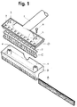
- figure 1, which is an exploded perspective view of the device according to a first embodiment of the invention;
- figures 2 is a perspective view of the device of figure 1;
- figure 3 is a transverse sectional view of the device of figure 1 in operating conditions thereof;
- figures 4 is a partially sectional top view of the device according to a second embodiment of the invention, and
- figure 5 is a transverse sectional view, taken along the plane X-X of the device of figure 4, illustrating the operating conditions thereof.
- From the accompanying drawings, it can be seen that the device according to the invention, similarly to other accessories for vacuum cleaners and liquid aspiration units, is shaped so as to define a chamber which is suitable for conveying toward the tubular handle, connected to the unit, all of the flows of material arriving from the aspiration intakes which are arranged, on the two sides of the rubber blade, along the entire operating front of the device.
- With reference to the first embodiment illustrated in greater detail in figures 1 and 2, it can be seen that the device is composed of:
- a rubber blade A;
- a blade holder B;
- a blade presser C;
- a cover D complete with a tubular handle to be gripped and inserted in a rigid or flexible intake duct.
- The rubber blade A, which is identical to those already mounted in glass-cleaning implements and liquid aspiration machines, has a toroidal enlarged edge for securing in the blade holder element B and, more specifically, between the internal recesses or
ridges 1 which delimit, together with said blade, the individual aspiration intakes. - Said recesses or
ridges 1 are shaped so as to prevent the downward extraction of the blade A, since said blade, which is inserted longitudinally in the blade holder, is secured thereat by the pressure of the blade presser C which is in turn pushed by the cover D. - Besides the above-mentioned
ridges 1 located on the two sides of the lower intake, the blade holder B has, inside it, two conical or cylindrical raisedportions 4 which are preferably provided with a threaded metallic bush and are in any case suitable for receiving thescrews 6 which fix the cover D to the blade holder B. - The element C or blade presser, which extends along the entire length of the blade holder B, has:
- a grid-like configuration, along its entire length, for the transverse passage of the aspiration flows arriving from the front intakes;
- a series of conical raised
portions 2 which protrude from the upper edge and are intended to be inserted into thecorresponding seats 3 of the cover D; - a series of transverse raised portions provided in the lower edge to cooperate with the
ridges 1 of the blade holder B in preventing the longitudinal extraction of the rubber A. - The cover D is advantageously defined monolithically, together with the
tubular handle 7 which, as in known vacuum cleaner accessories, acts as short handle and is also complete with couplings for insertion on rigid or flexible tubes which connect the device to the aspiration unit. - Said cover has an edge shaped so as to provide a sealed coupling with the blade holder B. The cover is provided, in an upward position, with the
holes 5 for thescrews 6 for fixing to the blade-holder and with a series ofseats 3. Theseats 3 are through holes or blind holes and are in any case shaped for accommodating the conical raisedportions 2 of the blade presser C. The blade presser C is maintained in the correct position by the engagement of the raisedportions 2 in theseats 3, and by theridges 1 of the blade holder B, between which it wedges. - The shape imparted to the three elements B, C and D is also a function of manufacturing requirements, since they are advantageously manufactured by injection molding in ABS, PVC or another thermoplastic material.
- It should be furthermore noted that the entire device can be easily inspected and cleaned after removing the only two
assembly screws 6, whereas in order to longitudinally extract or insert the blade A it is sufficient to loosen said screws without disassembling the entire device. - With reference to the second embodiment of the invention, illustrated in
drawing number 3, only the elements E and F are expediently made of thermoplastic material, since their assembly, by means of a pair ofscrews 14 screwed in theseats 13, allows to rigidly associate the torus of the rubber blade A between the recesses orridges - In this case, too, the upper element F is manufactured monolithically together with the
tubular handle 15 which, complete with appropriate known couplings, can be inserted in a rigid or flexible duct for connection to the liquid aspiration unit. - As in the preceding version, the loosening of the
screws 14 allows the longitudinal extraction and replacement of the blade A, whereas the complete removal of said screws and the consequent separation of the two elements allows the inspection and complete cleaning of the device. - It should be noted that in both of the described embodiments the rubber blade is rigidly associated exclusively in its toroidal region, since its entire planar portion, or most of it, is free to flex, in one direction or the other, depending on the sliding for cleaning and until it rests against one of the two rows of intakes.
- The mounting of the rubber blade furthermore allows said blade to protrude, at the two ends of the device, enough to pass so as to lightly contact the raised edges which delimit a glass pane or other surface to be cleaned.
- As already mentioned, the device according to the invention, without varying the described general characteristics, is susceptible to modifications or variations, also in relation to the dimensions.
- In this regard, the sizes which have a particularly wide cleaning front, are assembled with an adequate number of screws.
- Where technical features mentioned in any claim are followed by reference signs, those reference signs have been included for the sole purpose of increasing the intelligibility of the claims and accordingly such reference signs do not have any limiting effect on the scope of each element identified by way of example by such reference signs.
Claims (7)
- Device connectable to liquid aspiration units for cleaning glass panes and other flat surfaces, consisting of a tool which is active in two opposite directions of motion, is characterized in that comprises a blade holder having at least two parallel rows of aspiration openings or intakes which are separated by a rubber blade, of a known type, the elastic yielding whereof, in one direction or the other and according to the sliding imposed by the operator on the surface to be cleaned, determines the closure of one row of intakes and allows aspiration through the other row which is on the rake side of the rubber and consequently above the region for collecting the liquid to be aspirated.
- Device according to claim 1, characterized in that the rubber blade, which is of a known type and has such dimensions as to protrude at the two ends of the device, is rigidly associated exclusively in its own toroidal region so that its entire flat portion, or most of it, can flex freely, in one direction or the other, assisting its cleaning movement and until it rests against the row of intakes to be covered.
- Device according to the preceding claims, characterized in that it can be executed according to the embodiment of figures 1-2-3, which has the two rows of aspiration intakes arranged in a blade holder element B the internal recesses or ridges 1 whereof keep the torus of the rubber blade A centered and prevent its downward extraction despite the pressure from above of the blade presser element C, pushed by the cover D which, coupled to the blade holder B with screws or other equivalent means, delimits above the chamber which is connected to the tubular handle 7 to be connected to the aspiration unit by means of the coupling, in succession, of a possible rigid extension and of a flexible duct.
- Device according to the preceding claims, characterized in that the blade presser C, which is intended to act on the torus of the rubber A so that it protrudes uniformly from the blade holder B, has a series of openings for the transverse passage of the aspiration flows arriving from the front intakes of the device.
- Device according to the preceding claims, characterized in that the blade presser C, which is provided, in a downward position, with transverse ridges which cooperate with the ridges 1 of the blade holder so as to act on the torus of the rubber blade A, preventing its longitudinal extraction, is provided, in an upward position, with a series of conical teeth or raised portions 2 to be inserted in the corresponding through or blind seats 3 of the cover D so as to further secure the blade presser which is already wedged between the ridges 1.
- Device according to claims 1 and 2, characterized in that it can be executed according to the embodiment of figures 4 and 5, which has each of the two rows of aspiration intakes defined in one of the two elements E and F which, joined by screws or other equivalent means, secure the torus of the rubber blade A between the respective ridges 11 and 12 which form said intakes.
- Device according to claim 6, characterized in that the chamber formed by the two elements E and F is connected to the aspiration unit through the tubular handle 15 of F which is appropriately preset for the coupling of a possible rigid extension or of a flexible duct.
Priority Applications (1)
| Application Number | Priority Date | Filing Date | Title |
|---|---|---|---|
| EP91121816A EP0547267A1 (en) | 1991-12-19 | 1991-12-19 | Device connectable to liquid aspiration units for cleaning flat surfaces |
Applications Claiming Priority (1)
| Application Number | Priority Date | Filing Date | Title |
|---|---|---|---|
| EP91121816A EP0547267A1 (en) | 1991-12-19 | 1991-12-19 | Device connectable to liquid aspiration units for cleaning flat surfaces |
Publications (1)
| Publication Number | Publication Date |
|---|---|
| EP0547267A1 true EP0547267A1 (en) | 1993-06-23 |
Family
ID=8207452
Family Applications (1)
| Application Number | Title | Priority Date | Filing Date |
|---|---|---|---|
| EP91121816A Withdrawn EP0547267A1 (en) | 1991-12-19 | 1991-12-19 | Device connectable to liquid aspiration units for cleaning flat surfaces |
Country Status (1)
| Country | Link |
|---|---|
| EP (1) | EP0547267A1 (en) |
Cited By (7)
| Publication number | Priority date | Publication date | Assignee | Title |
|---|---|---|---|---|
| US5819365A (en) * | 1995-09-08 | 1998-10-13 | Bissell Inc. | Window washing accessory cleaning tool for use with water extraction cleaning machine |
| FR2768716A1 (en) * | 1997-09-22 | 1999-03-26 | Gilles Dominique Oberti | Extractor for dregs from liquid tank |
| EP1623764A2 (en) | 1998-05-01 | 2006-02-08 | Gen-Probe Incorporated | Automated process for isolating and amplifying a target nucleic acid sequence |
| EP2322940A1 (en) | 2005-03-10 | 2011-05-18 | Gen-Probe Incorporated | Systems amd methods to perform assays for detecting or quantifing analytes within samples |
| EP2348320A2 (en) | 2005-03-10 | 2011-07-27 | Gen-Probe Incorporated | Systems and methods for detecting multiple optical signals |
| EP3549503B1 (en) * | 2016-12-02 | 2023-03-08 | Skybest Electric Appliance (Suzhou) Co., Ltd. | Water absorption brush head and wet/dry vacuum cleaner with same |
| JP2023173750A (en) * | 2022-05-26 | 2023-12-07 | 工機ホールディングス株式会社 | Nozzles and implements |
Citations (7)
| Publication number | Priority date | Publication date | Assignee | Title |
|---|---|---|---|---|
| US2218595A (en) * | 1939-03-01 | 1940-10-22 | Kent Company Inc | Water pickup tool |
| US3072951A (en) * | 1961-05-16 | 1963-01-15 | Fabmagic Inc | Vacuum cleaner pickup head |
| US3210792A (en) * | 1964-01-17 | 1965-10-12 | Gen Floorcraft Inc | Vacuum mopping device |
| DE1931968U (en) * | 1965-11-10 | 1966-02-03 | Electrostar G M B H | DUESE FOR VACUUM CLEANER. |
| DE6906522U (en) * | 1968-02-20 | 1969-10-16 | Hoover Ltd | VACUUM CLEANER WET RECEPTION NOZZLE |
| DE2139157A1 (en) * | 1971-08-05 | 1973-02-15 | Andrae P Kg | Sucker mouthpiece |
| EP0128608A1 (en) * | 1983-06-13 | 1984-12-19 | Shop-Vac Corporation | Shoe attachment for wet/dry electric vacuum cleaner |
-
1991
- 1991-12-19 EP EP91121816A patent/EP0547267A1/en not_active Withdrawn
Patent Citations (7)
| Publication number | Priority date | Publication date | Assignee | Title |
|---|---|---|---|---|
| US2218595A (en) * | 1939-03-01 | 1940-10-22 | Kent Company Inc | Water pickup tool |
| US3072951A (en) * | 1961-05-16 | 1963-01-15 | Fabmagic Inc | Vacuum cleaner pickup head |
| US3210792A (en) * | 1964-01-17 | 1965-10-12 | Gen Floorcraft Inc | Vacuum mopping device |
| DE1931968U (en) * | 1965-11-10 | 1966-02-03 | Electrostar G M B H | DUESE FOR VACUUM CLEANER. |
| DE6906522U (en) * | 1968-02-20 | 1969-10-16 | Hoover Ltd | VACUUM CLEANER WET RECEPTION NOZZLE |
| DE2139157A1 (en) * | 1971-08-05 | 1973-02-15 | Andrae P Kg | Sucker mouthpiece |
| EP0128608A1 (en) * | 1983-06-13 | 1984-12-19 | Shop-Vac Corporation | Shoe attachment for wet/dry electric vacuum cleaner |
Cited By (16)
| Publication number | Priority date | Publication date | Assignee | Title |
|---|---|---|---|---|
| US5819365A (en) * | 1995-09-08 | 1998-10-13 | Bissell Inc. | Window washing accessory cleaning tool for use with water extraction cleaning machine |
| FR2768716A1 (en) * | 1997-09-22 | 1999-03-26 | Gilles Dominique Oberti | Extractor for dregs from liquid tank |
| EP1623764A2 (en) | 1998-05-01 | 2006-02-08 | Gen-Probe Incorporated | Automated process for isolating and amplifying a target nucleic acid sequence |
| EP1925367A1 (en) | 1998-05-01 | 2008-05-28 | Gen-Probe Incorporated | System for agitating the contents of a container |
| EP2082806A2 (en) | 1998-05-01 | 2009-07-29 | Gen-Probe Incorporated | Automated diagnostic analyzer and method |
| EP2156891A2 (en) | 1998-05-01 | 2010-02-24 | Gen-Probe Incorporated | System and method for incubating the contents of a reaction receptacle |
| EP2295144A2 (en) | 1998-05-01 | 2011-03-16 | Gen-Probe Incorporated | System and method for incubating the contents of a reaction receptacle |
| EP2316570A2 (en) | 1998-05-01 | 2011-05-04 | Gen-Probe Incorporated | Automated diagnostic analyzer and method |
| EP2316571A2 (en) | 1998-05-01 | 2011-05-04 | Gen-Probe Incorporated | Automated diagnostic analyzer and method |
| EP2316572A2 (en) | 1998-05-01 | 2011-05-04 | Gen-Probe Incorporated | Automated diagnostic analyzer and method |
| EP2322940A1 (en) | 2005-03-10 | 2011-05-18 | Gen-Probe Incorporated | Systems amd methods to perform assays for detecting or quantifing analytes within samples |
| EP2333561A2 (en) | 2005-03-10 | 2011-06-15 | Gen-Probe Incorporated | System for performing multi-formatted assays |
| EP2348320A2 (en) | 2005-03-10 | 2011-07-27 | Gen-Probe Incorporated | Systems and methods for detecting multiple optical signals |
| EP2348321A2 (en) | 2005-03-10 | 2011-07-27 | Gen-Probe Incorporated | System and methods to perform assays for detecting or quantifying analytes within samples |
| EP3549503B1 (en) * | 2016-12-02 | 2023-03-08 | Skybest Electric Appliance (Suzhou) Co., Ltd. | Water absorption brush head and wet/dry vacuum cleaner with same |
| JP2023173750A (en) * | 2022-05-26 | 2023-12-07 | 工機ホールディングス株式会社 | Nozzles and implements |
Similar Documents
| Publication | Publication Date | Title |
|---|---|---|
| KR100392606B1 (en) | cyclone dust-collecting apparatus for vacuum cleaner | |
| US6023811A (en) | Modular tool to remove grout | |
| DK0422977T3 (en) | Vacuum cleaner with scraper for removing dirty water while cleaning certain surfaces | |
| US4557013A (en) | Vacuum coupled squeegee attachment | |
| EP0547267A1 (en) | Device connectable to liquid aspiration units for cleaning flat surfaces | |
| US4823431A (en) | Fan blade cleaning device | |
| EP3393320B1 (en) | Suction nozzle for a hard surface cleaning device and hard surface cleaning device having a suction nozzle of this type | |
| DE602004016813D1 (en) | Vacuum cleaner with a device for a flexible hose | |
| DE102019131614A1 (en) | Vacuum cleaner, dust bag and cleaning system | |
| US20170258283A1 (en) | Vacuum Attachment for Picking Up an Object | |
| KR100420168B1 (en) | Cyclone dust-collecting apparatus for vacuum cleaner | |
| KR20020028451A (en) | handle structure of vacuum cleaner | |
| IT9012018A1 (en) | ACCESSORY DEVICE TO BE CONNECTED TO VACUUM CLEANERS TO CLEAN GLASSES AND OTHER FLAT SURFACES. | |
| KR970000472Y1 (en) | Dust collection paper of vacuum cleaner | |
| KR100232561B1 (en) | A vacuum cleaner | |
| KR0117464Y1 (en) | Brush removal device of vacuum inlet | |
| KR101953739B1 (en) | push stick type cleaning apparatus | |
| JP3013946U (en) | Moss remover | |
| JP3034259U (en) | Filter cleaning device | |
| KR930005008Y1 (en) | Six season left and right interlock | |
| KR200155789Y1 (en) | Suction member flow device of vacuum cleaner | |
| KR960002520Y1 (en) | Inlet for cleaning corners of vacuum cleaners | |
| KR910002379Y1 (en) | A cleaning device combined with squeezing plates | |
| JPS6221265Y2 (en) | ||
| KR890000984Y1 (en) | Inlet of vacuum cleaner |
Legal Events
| Date | Code | Title | Description |
|---|---|---|---|
| PUAI | Public reference made under article 153(3) epc to a published international application that has entered the european phase |
Free format text: ORIGINAL CODE: 0009012 |
|
| AK | Designated contracting states |
Kind code of ref document: A1 Designated state(s): CH DE ES FR LI NL |
|
| RAP1 | Party data changed (applicant data changed or rights of an application transferred) |
Owner name: LOMBARDI CELSO AND SIMONCELLI LORIS, TRADING UNDER |
|
| 17P | Request for examination filed |
Effective date: 19931123 |
|
| 17Q | First examination report despatched |
Effective date: 19950206 |
|
| RAP1 | Party data changed (applicant data changed or rights of an application transferred) |
Owner name: LOMBARDI E SIMONCELLI SNC |
|
| STAA | Information on the status of an ep patent application or granted ep patent |
Free format text: STATUS: THE APPLICATION HAS BEEN WITHDRAWN |
|
| 18W | Application withdrawn |
Withdrawal date: 19960520 |