EP0545876B1 - Aktiver Annäherungszünder - Google Patents
Aktiver Annäherungszünder Download PDFInfo
- Publication number
- EP0545876B1 EP0545876B1 EP92850271A EP92850271A EP0545876B1 EP 0545876 B1 EP0545876 B1 EP 0545876B1 EP 92850271 A EP92850271 A EP 92850271A EP 92850271 A EP92850271 A EP 92850271A EP 0545876 B1 EP0545876 B1 EP 0545876B1
- Authority
- EP
- European Patent Office
- Prior art keywords
- electromagnetic radiation
- receiver
- proximity fuse
- radiation
- polarisation
- Prior art date
- Legal status (The legal status is an assumption and is not a legal conclusion. Google has not performed a legal analysis and makes no representation as to the accuracy of the status listed.)
- Expired - Lifetime
Links
Images
Classifications
-
- F—MECHANICAL ENGINEERING; LIGHTING; HEATING; WEAPONS; BLASTING
- F42—AMMUNITION; BLASTING
- F42C—AMMUNITION FUZES; ARMING OR SAFETY MEANS THEREFOR
- F42C13/00—Proximity fuzes; Fuzes for remote detonation
- F42C13/02—Proximity fuzes; Fuzes for remote detonation operated by intensity of light or similar radiation
- F42C13/023—Proximity fuzes; Fuzes for remote detonation operated by intensity of light or similar radiation using active distance measurement
-
- G—PHYSICS
- G01—MEASURING; TESTING
- G01S—RADIO DIRECTION-FINDING; RADIO NAVIGATION; DETERMINING DISTANCE OR VELOCITY BY USE OF RADIO WAVES; LOCATING OR PRESENCE-DETECTING BY USE OF THE REFLECTION OR RERADIATION OF RADIO WAVES; ANALOGOUS ARRANGEMENTS USING OTHER WAVES
- G01S7/00—Details of systems according to groups G01S13/00, G01S15/00, G01S17/00
- G01S7/48—Details of systems according to groups G01S13/00, G01S15/00, G01S17/00 of systems according to group G01S17/00
- G01S7/499—Details of systems according to groups G01S13/00, G01S15/00, G01S17/00 of systems according to group G01S17/00 using polarisation effects
Definitions
- the present invention relates to an active proximity fuse for a launchable unit such as a missile, rocket, projectile and so forth.
- the proximity fuse comprises a transmitter for transmitting linearly polarised electromagnetic radiation towards a target and a receiver for receiving the transmitted electromagnetic radiation which is reflected towards the receiver.
- electromagnetic radiation is meant preferably but not exclusively optical light.
- a reference plane is defined as the plane in which electromagnetic radiation emitted from the transmitter towards the target is transmitted between the transmitter and receiver.
- the receiver comprises a detector for detecting the electromagnetic radiation and signal-comparing elements.
- a proximity fuse according to the above is known from US-A-4 859 054.
- a linearly polarised electromagnetic radiation may be emitted if a laser with inherent polarisation is used as lighting source.
- the distance range is determined by comparing the reflected radiation with an internally delayed version of the radiation.
- the target or an area of the target is imaged as a spot on a detector in the receiver.
- An electrical signal is received at the detector output which varies as a function of the distance to the target and the capability of the target surface to reflect the electromagnetical radiation emitted by the transmitter.
- the electrical signal can be compared with a fixed reference level and when this is exceeded, the proximity fuse thereby delivers an output signal which can be utilised by the launchable unit for a weapon charge, as an example.
- Proximity fuses comparing the signals in accordance with the preceding paragraph are previously known, and in this connection reference can be made, for example, to EP-A-345 383.
- the operation of the proximity fuse can be disturbed by spherical particles which occur in the atmosphere. Examples of such particles are water drops in haze, fog, clouds. These particles reflect some of the electromagnetic radiation emitted by the transmitter of the proximity fuse towards the receiver of the proximity fuse. This makes it more difficult to distinguish the radiation reflected by the target and the accuracy is impaired.
- an active proximity fuse which is characterised by the fact that the transmitter is arranged to emit linearly polarized electromagnetic radiation in parallel with or orthogonally to the reference plane, that the receiver comprises elements for suppressing electromagnetic radiation received by the receiver with linear polarisation essentially coinciding with the linear polarisation direction of the emitted electromagnetic radiation, that the detector is arranged to detect the electromagnetic radiation remaining after suppression and that the signal-comparing elements are arranged to compare the level of the remaining electromagnetic radiation detected by said detector with a fixed reference level and to emit an output signal when an output signal of the detector exceeds said fixed reference level for starting up a weapon charge.
- the invention prevents radiation reflected from spherical particles from reaching the detector of the receiver. This follows from the natural laws.
- the direction of the electrical field vector of the radiation of linearly polarised radiation which is reflected from a homogeneous spherical particle remains unchanged relative to a reference plane which contains both incoming and outgoing ray, with the prerequisite that the direction of polarisation of the outgoing ray is orthogonal to or parallel with the reference plane.
- Linearly polarised radiation which reaches the target will, on the other hand be wholly or partially depolarised with the diffuse reflection from the target surface.
- the ratio between the useful signal, that is to say the radiation reflected by the target, and the useless signal, that is to say radiation reflected from spherical particles in the atmosphere, can thereby be improved.
- the proximity fuse can therefore operate with high accuracy regardless of the radiation which hits the receiver as a consequence of reflections of the emitted radiation from spherical particles in the atmosphere.
- a satisfactory operation of the proximity fuse is also obtained in difficult types of weather, since the received electromagnetic radiation with linear polarisation coinciding with the linear polarisation direction of the emitted radiation can be suppressed wholly or partially.
- a laser diode with linear polarisation is arranged for producing the electromagnetic radiation emitted by the transmitter.
- a linear polarized HeNe laser be used.
- the element in the receiver for suppressing the electromagnetic radiation essentially coinciding with the linear direction of polarisation of the emitted electromagnetic radiation consists of a polarisation filter.
- the polarisation filter can advantageously consist of a dichroic polariser or a GLAN prism.
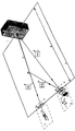
- the proximity fuse shown in basic diagrammatic form, comprises a transmitter (1) and a receiver (8).
- Transmitter (1) and receiver (8) of the proximity fuse are placed at a distance from one another and aligned in such a manner that the photons sent out from the transmitter, and which later reach the receiver after exactly one reflection, have travelled in an unambiguously defined plane, called reference plane (7) hereinafter.
- the transmitter (1) irradiates a target (3), which is present within the operating field (4) of the proximity fuse, with a narrow transmitting lobe (2).
- the electromagnetic radiation in the transmitting lobe is produced with the aid of a laser diode (5) with inbuilt linear polaristion.
- a linear polarized HeNe laser can be used with a wavelength of 540 nm.
- the laser diode (5) is oriented relative to the reference plane (7) in such a manner that the emitted radiation (6) is linearly polarised with the electrical field vector orthogonal to the reference plane (7).
- the emitted radiation can be linearly polarised with the electrical field vector parallel with the reference plane.
- a lens arrangement is arranged in the transmitter for finally shaping the transmitting lobe (2) for the radiation emitted by the laser diode (5).
- the receiver contains a lens arrangement (15) which focuses the radiation received at the receiver input on a detector (13). Between the lens arrangement (15) and the detector (13), the receiver is provided with a polarisation filter (12).
- the filter can consist of a polariser or a prism.
- a comparator (16) is arranged to compare the output signal from the detector (13) with a fixed reference level. An output signal is emitted when the detector output signal exceeds the fixed reference level.
- Radiation which is sent out by the transmitter (1) is reflected back to the receiver of the proximity fuse partially as useful radiation (9) after having been reflected from the target and partially as useless radiation (11) after having been reflected from atmospheric particles (10), for example spherical water droplets.
- the radiation which has been reflected from the target is wholly or partially depolarised, whilst the radiation which has been reflected from spherical particles is polarised in exactly the same way as the emitted radiation.
- the polarisation filter 12 is oriented in such a manner that radiation with the electrical field vector in the reference plane 7 is transmitted. Radiation with an electrical field vector orthogonal to the reference plane is stopped wholly or partially.
- the polarisation filter (12) thereby prevents the useless radiation from reaching the detector 13 at the same time as the filter passes the part of the useful radiation which is polarised orthogonally to the emitted radiation.
- a favourable ratio between useful and useless signals is obtained in the detector (13).
- the emitted radiation has been assumed to be linearly polarised with the electrical field vector orthogonal to the reference plane.
- the electrical field vector can be placed in the reference plane if, at the same time, the polarisation filter is turned by 90°.
Landscapes
- Engineering & Computer Science (AREA)
- General Engineering & Computer Science (AREA)
- Computer Networks & Wireless Communication (AREA)
- Physics & Mathematics (AREA)
- General Physics & Mathematics (AREA)
- Radar, Positioning & Navigation (AREA)
- Remote Sensing (AREA)
- Optical Radar Systems And Details Thereof (AREA)
- Geophysics And Detection Of Objects (AREA)
- Air Bags (AREA)
- Steering Controls (AREA)
- Techniques For Improving Reliability Of Storages (AREA)
- Design And Manufacture Of Integrated Circuits (AREA)
- Auxiliary Drives, Propulsion Controls, And Safety Devices (AREA)
- Switches Operated By Changes In Physical Conditions (AREA)
- Fire-Detection Mechanisms (AREA)
- Investigating Or Analysing Materials By Optical Means (AREA)
- Rigid Pipes And Flexible Pipes (AREA)
- Control Of Combustion (AREA)
- Display Devices Of Pinball Game Machines (AREA)
Claims (6)
- Aktiver Annäherungszünder für eine abschießbare Einheit wie Flugkörper, Rakete, Geschoß u. dgl., mit einem Sender (1) zum Aussenden von linear polarisierter elektromagnetischer Strahlung zu einem Ziel und einem Empfänger (3) zum Empfangen der emittierten elektromagnetischen Strahlung, die zum Empfänger reflektiert wird, wobei der Empfänger einen Detektor (13) zum Detektieren der elektromagnetischen Strahlung und Signalvergleichelemente aufweist, und wobei eine Bezugsebene (7) definiert ist als eine Ebene, in der vom Sender emittierte elektromagnetische Strahlung zwischen dem Sender und Empfänger übertragen wird,
dadurch gekennzeichnet, daß der Sender (1) so eingerichtet ist, daß er linear polarisierte elektromagnetische Strahlung parallel oder rechtwinklig zu der Bezugsebene (7) emittiert, daß der Empfänger (8) Elemente zum Unterdrücken von vom Empfänger empfangener elektromagnetischer Strahlung aufweist, deren lineare Polarisierung im wesentlichen mit der linearen Polarisationsrichtung der emittierten elektromagnetischen Strahlung zusammenfällt, daß der Detektor (13) so angeordnet ist, daß er die nach der Unterdrückung verbleibende elektromagnetische Strahlung detektiert, und daß die signalvergleichenden Elemente so angeordnet sind, daß sie den Pegel der vom Detektor detektierten verbleibenden elektromagnetischen Strahlung mit einem festen Bezugspegel vergleichen und ein Ausgangssignal emittieren, wenn ein Ausgangssignal des Detektors den festen Bezugspegel übersteigt, um eine Waffenladung auszulösen. - Annäherungszünder nach Anspruch 1,
dadurch gekennzeichnet, daß eine Laserdiode (5) mit linearer Polarisierung zum Erzeugen der vom Sender emittierten elektromagnetischen Strahlung vorgesehen ist. - Annäherungszünder nach Anspruch 1,
dadurch gekennzeichnet, daß ein linear polarisierter NENE-Laser zum Erzeugen der vom Sender (1) emittierten elektromagnetischen Strahlung vorgesehen ist. - Annäherungszünder nach einem der vorangehenden Ansprüche,
dadurch gekennzeichnet, daß das Element in dem Empfänger (8) zum Unterdrücken von elektromagnetischer Strahlung, die mit der linearen Polarisationsrichtung der emittierten elektromagnetischen Strahlung im wesentlichen übereinstimmt, aus einem Polarisationsfilter (10) besteht. - Annäherungszünder nach Anspruch 4,
dadurch gekennzeichnet, daß das Polarisationsfilter (12) aus einem dichroitischen Polarisator besteht. - Annäherungszünder nach Anspruch 4,
dadurch gekennzeichnet, daß das Polarisationsfilter (12) aus einem GLAN-Prisma besteht.
Applications Claiming Priority (2)
| Application Number | Priority Date | Filing Date | Title |
|---|---|---|---|
| SE9103602 | 1991-12-04 | ||
| SE9103602A SE9103602L (sv) | 1991-12-04 | 1991-12-04 | Anordning foer missil eller dyl |
Publications (2)
| Publication Number | Publication Date |
|---|---|
| EP0545876A1 EP0545876A1 (de) | 1993-06-09 |
| EP0545876B1 true EP0545876B1 (de) | 1997-01-08 |
Family
ID=20384524
Family Applications (1)
| Application Number | Title | Priority Date | Filing Date |
|---|---|---|---|
| EP92850271A Expired - Lifetime EP0545876B1 (de) | 1991-12-04 | 1992-11-17 | Aktiver Annäherungszünder |
Country Status (8)
| Country | Link |
|---|---|
| US (1) | US5322017A (de) |
| EP (1) | EP0545876B1 (de) |
| AT (1) | ATE147505T1 (de) |
| CA (1) | CA2084433C (de) |
| DE (1) | DE69216567T2 (de) |
| ES (1) | ES2095452T3 (de) |
| NO (1) | NO301301B1 (de) |
| SE (1) | SE9103602L (de) |
Families Citing this family (3)
| Publication number | Priority date | Publication date | Assignee | Title |
|---|---|---|---|---|
| DE10207923B4 (de) * | 2002-02-23 | 2005-09-22 | Diehl Bgt Defence Gmbh & Co. Kg | Annäherungssensor, insbesondere für die Zündauslösung des Gefechtskopfes einer Abwehrgranate gegen ein anfliegendes Projektil |
| US7525657B2 (en) * | 2007-03-07 | 2009-04-28 | Raytheon Company | System and method for active optical target detection with polarized receiver |
| US10935357B2 (en) | 2018-04-25 | 2021-03-02 | Bae Systems Information And Electronic Systems Integration Inc. | Proximity fuse having an E-field sensor |
Family Cites Families (8)
| Publication number | Priority date | Publication date | Assignee | Title |
|---|---|---|---|---|
| US3918059A (en) * | 1959-03-06 | 1975-11-04 | Us Navy | Chaff discrimination system |
| DE3114279C2 (de) * | 1981-04-09 | 1983-06-16 | Messerschmitt-Bölkow-Blohm GmbH, 8000 München | Zielsuchkopf für Flugkörper |
| US4752799A (en) * | 1986-07-07 | 1988-06-21 | Honeywell Inc. | Optical proximity sensing optics |
| SE458480B (sv) * | 1986-12-11 | 1989-04-03 | Bofors Ab | Anordning i zonroer foer uppskjutbar enhet, innefattande saendare och mottagare foer optisk straalning |
| US4733609A (en) * | 1987-04-03 | 1988-03-29 | Digital Signal Corporation | Laser proximity sensor |
| US4859054A (en) * | 1987-07-10 | 1989-08-22 | The United States Of America As Represented By The United States Department Of Energy | Proximity fuze |
| DE3930272A1 (de) * | 1988-10-05 | 1990-04-19 | Impulsphysik Gmbh | Lidar |
| DE4007646C2 (de) * | 1990-03-10 | 2003-08-07 | Daimler Chrysler Ag | Anordnung zur Verbesserung der Sicht in Fahrzeugen |
-
1991
- 1991-12-04 SE SE9103602A patent/SE9103602L/ not_active Application Discontinuation
-
1992
- 1992-11-17 AT AT92850271T patent/ATE147505T1/de not_active IP Right Cessation
- 1992-11-17 EP EP92850271A patent/EP0545876B1/de not_active Expired - Lifetime
- 1992-11-17 ES ES92850271T patent/ES2095452T3/es not_active Expired - Lifetime
- 1992-11-17 DE DE69216567T patent/DE69216567T2/de not_active Expired - Fee Related
- 1992-12-01 US US07/983,717 patent/US5322017A/en not_active Expired - Lifetime
- 1992-12-03 CA CA002084433A patent/CA2084433C/en not_active Expired - Fee Related
- 1992-12-03 NO NO924666A patent/NO301301B1/no not_active IP Right Cessation
Also Published As
| Publication number | Publication date |
|---|---|
| NO924666D0 (no) | 1992-12-03 |
| DE69216567D1 (de) | 1997-02-20 |
| ATE147505T1 (de) | 1997-01-15 |
| ES2095452T3 (es) | 1997-02-16 |
| EP0545876A1 (de) | 1993-06-09 |
| DE69216567T2 (de) | 1997-05-28 |
| NO924666L (no) | 1993-06-07 |
| CA2084433A1 (en) | 1993-06-05 |
| SE9103602L (sv) | 1993-06-05 |
| CA2084433C (en) | 2003-02-11 |
| NO301301B1 (no) | 1997-10-06 |
| US5322017A (en) | 1994-06-21 |
Similar Documents
| Publication | Publication Date | Title |
|---|---|---|
| US4763361A (en) | System and device for recognition or IFF use | |
| CN110487120B (zh) | 一种远距离照明的激光防御系统及方法 | |
| EP0005852B1 (de) | Reflektionslichtschranke geeignet für das Erkennen stark reflektierender Gegenstände | |
| US20240201329A1 (en) | Polarization sensitive lidar system | |
| CA2243752A1 (en) | Magic mirror hot spot tracker | |
| US20210011162A1 (en) | Polarization Filtering in LiDAR System | |
| US8169597B2 (en) | Method and apparatus for laser return characterization in a countermeasures system | |
| CA2084433C (en) | Active proximity fuse | |
| EP0345383A1 (de) | Empfänger für optische Strahlung | |
| US20050201096A1 (en) | Object detecting apparatus for vehicle | |
| WO2014174035A1 (en) | Seeker systems | |
| CA2255170A1 (en) | Adaptive focal plane for high contrast imaging | |
| US7599045B2 (en) | Method for eliminating internal reflection of range finding system and range finding system applying the same | |
| US6166803A (en) | Imaging simplified laser pointing (ISLAPS)--A system modification/improvement | |
| ATE147157T1 (de) | Aktiver optischer annäherungszünder | |
| US20190285731A1 (en) | Optical detection of an object in a turbid medium using an optical vortex | |
| US5040892A (en) | Method and apparatus for determining the direction to a laser beam source | |
| JP2557976B2 (ja) | 近接信管装置 | |
| RU2350889C2 (ru) | Двухканальное устройство обнаружения наземных объектов | |
| US20060181694A1 (en) | Method for eliminating internal reflection of range finding system and range finding system applying the same | |
| JP2557989B2 (ja) | 近接信管装置 | |
| JPH0227632A (ja) | 回帰反射型光電スイッチ | |
| JP2664509B2 (ja) | 近接信管装置 | |
| Vižintin | Angular Resolution in Laser Warning Devices | |
| Ballard | Auto-aligning laser boresight |
Legal Events
| Date | Code | Title | Description |
|---|---|---|---|
| PUAI | Public reference made under article 153(3) epc to a published international application that has entered the european phase |
Free format text: ORIGINAL CODE: 0009012 |
|
| AK | Designated contracting states |
Kind code of ref document: A1 Designated state(s): AT BE CH DE DK ES FR GB GR IT LI NL SE |
|
| 17P | Request for examination filed |
Effective date: 19931012 |
|
| 17Q | First examination report despatched |
Effective date: 19950322 |
|
| GRAG | Despatch of communication of intention to grant |
Free format text: ORIGINAL CODE: EPIDOS AGRA |
|
| GRAH | Despatch of communication of intention to grant a patent |
Free format text: ORIGINAL CODE: EPIDOS IGRA |
|
| GRAH | Despatch of communication of intention to grant a patent |
Free format text: ORIGINAL CODE: EPIDOS IGRA |
|
| GRAA | (expected) grant |
Free format text: ORIGINAL CODE: 0009210 |
|
| AK | Designated contracting states |
Kind code of ref document: B1 Designated state(s): AT BE CH DE DK ES FR GB GR IT LI NL SE |
|
| PG25 | Lapsed in a contracting state [announced via postgrant information from national office to epo] |
Ref country code: LI Effective date: 19970108 Ref country code: GR Free format text: LAPSE BECAUSE OF FAILURE TO SUBMIT A TRANSLATION OF THE DESCRIPTION OR TO PAY THE FEE WITHIN THE PRESCRIBED TIME-LIMIT Effective date: 19970108 Ref country code: DK Effective date: 19970108 Ref country code: CH Effective date: 19970108 Ref country code: AT Effective date: 19970108 |
|
| REF | Corresponds to: |
Ref document number: 147505 Country of ref document: AT Date of ref document: 19970115 Kind code of ref document: T |
|
| ITF | It: translation for a ep patent filed | ||
| REG | Reference to a national code |
Ref country code: CH Ref legal event code: EP |
|
| ET | Fr: translation filed | ||
| REG | Reference to a national code |
Ref country code: ES Ref legal event code: FG2A Ref document number: 2095452 Country of ref document: ES Kind code of ref document: T3 |
|
| REF | Corresponds to: |
Ref document number: 69216567 Country of ref document: DE Date of ref document: 19970220 |
|
| REG | Reference to a national code |
Ref country code: CH Ref legal event code: PL |
|
| K1C1 | Correction of patent application (title page) published |
Effective date: 19930609 |
|
| PLBE | No opposition filed within time limit |
Free format text: ORIGINAL CODE: 0009261 |
|
| 26N | No opposition filed | ||
| REG | Reference to a national code |
Ref country code: GB Ref legal event code: IF02 |
|
| PGFP | Annual fee paid to national office [announced via postgrant information from national office to epo] |
Ref country code: ES Payment date: 20031209 Year of fee payment: 12 |
|
| PGFP | Annual fee paid to national office [announced via postgrant information from national office to epo] |
Ref country code: BE Payment date: 20040121 Year of fee payment: 12 |
|
| PG25 | Lapsed in a contracting state [announced via postgrant information from national office to epo] |
Ref country code: ES Free format text: LAPSE BECAUSE OF NON-PAYMENT OF DUE FEES Effective date: 20041118 |
|
| PG25 | Lapsed in a contracting state [announced via postgrant information from national office to epo] |
Ref country code: BE Free format text: LAPSE BECAUSE OF NON-PAYMENT OF DUE FEES Effective date: 20041130 |
|
| BERE | Be: lapsed |
Owner name: *BOFORS A.B. Effective date: 20041130 |
|
| REG | Reference to a national code |
Ref country code: ES Ref legal event code: FD2A Effective date: 20041118 |
|
| BERE | Be: lapsed |
Owner name: *BOFORS A.B. Effective date: 20041130 |
|
| REG | Reference to a national code |
Ref country code: GB Ref legal event code: 732E |
|
| NLS | Nl: assignments of ep-patents |
Owner name: SAAB AB Effective date: 20080421 |
|
| NLT1 | Nl: modifications of names registered in virtue of documents presented to the patent office pursuant to art. 16 a, paragraph 1 |
Owner name: SAAB BOFORS AKTIEBOLAG |
|
| REG | Reference to a national code |
Ref country code: FR Ref legal event code: TP |
|
| PGFP | Annual fee paid to national office [announced via postgrant information from national office to epo] |
Ref country code: NL Payment date: 20081103 Year of fee payment: 17 Ref country code: DE Payment date: 20081114 Year of fee payment: 17 |
|
| PGFP | Annual fee paid to national office [announced via postgrant information from national office to epo] |
Ref country code: SE Payment date: 20081107 Year of fee payment: 17 Ref country code: IT Payment date: 20081126 Year of fee payment: 17 |
|
| PGFP | Annual fee paid to national office [announced via postgrant information from national office to epo] |
Ref country code: FR Payment date: 20081112 Year of fee payment: 17 |
|
| PGFP | Annual fee paid to national office [announced via postgrant information from national office to epo] |
Ref country code: GB Payment date: 20081112 Year of fee payment: 17 |
|
| REG | Reference to a national code |
Ref country code: NL Ref legal event code: V1 Effective date: 20100601 |
|
| EUG | Se: european patent has lapsed | ||
| GBPC | Gb: european patent ceased through non-payment of renewal fee |
Effective date: 20091117 |
|
| REG | Reference to a national code |
Ref country code: FR Ref legal event code: ST Effective date: 20100730 |
|
| PG25 | Lapsed in a contracting state [announced via postgrant information from national office to epo] |
Ref country code: NL Free format text: LAPSE BECAUSE OF NON-PAYMENT OF DUE FEES Effective date: 20100601 Ref country code: FR Free format text: LAPSE BECAUSE OF NON-PAYMENT OF DUE FEES Effective date: 20091130 |
|
| PG25 | Lapsed in a contracting state [announced via postgrant information from national office to epo] |
Ref country code: DE Free format text: LAPSE BECAUSE OF NON-PAYMENT OF DUE FEES Effective date: 20100601 |
|
| PG25 | Lapsed in a contracting state [announced via postgrant information from national office to epo] |
Ref country code: GB Free format text: LAPSE BECAUSE OF NON-PAYMENT OF DUE FEES Effective date: 20091117 |
|
| PG25 | Lapsed in a contracting state [announced via postgrant information from national office to epo] |
Ref country code: IT Free format text: LAPSE BECAUSE OF NON-PAYMENT OF DUE FEES Effective date: 20091117 |
|
| PG25 | Lapsed in a contracting state [announced via postgrant information from national office to epo] |
Ref country code: SE Free format text: LAPSE BECAUSE OF NON-PAYMENT OF DUE FEES Effective date: 20091118 |