EP0545534A1 - Stabilisation à long terme du mode d'un laser de type réflecteur de Bragg distribué - Google Patents
Stabilisation à long terme du mode d'un laser de type réflecteur de Bragg distribué Download PDFInfo
- Publication number
- EP0545534A1 EP0545534A1 EP92309618A EP92309618A EP0545534A1 EP 0545534 A1 EP0545534 A1 EP 0545534A1 EP 92309618 A EP92309618 A EP 92309618A EP 92309618 A EP92309618 A EP 92309618A EP 0545534 A1 EP0545534 A1 EP 0545534A1
- Authority
- EP
- European Patent Office
- Prior art keywords
- bragg
- bragg section
- section
- laser
- current
- Prior art date
- Legal status (The legal status is an assumption and is not a legal conclusion. Google has not performed a legal analysis and makes no representation as to the accuracy of the status listed.)
- Granted
Links
Images


Classifications
-
- H—ELECTRICITY
- H01—ELECTRIC ELEMENTS
- H01S—DEVICES USING THE PROCESS OF LIGHT AMPLIFICATION BY STIMULATED EMISSION OF RADIATION [LASER] TO AMPLIFY OR GENERATE LIGHT; DEVICES USING STIMULATED EMISSION OF ELECTROMAGNETIC RADIATION IN WAVE RANGES OTHER THAN OPTICAL
- H01S5/00—Semiconductor lasers
- H01S5/06—Arrangements for controlling the laser output parameters, e.g. by operating on the active medium
- H01S5/068—Stabilisation of laser output parameters
- H01S5/0683—Stabilisation of laser output parameters by monitoring the optical output parameters
- H01S5/0687—Stabilising the frequency of the laser
-
- H—ELECTRICITY
- H04—ELECTRIC COMMUNICATION TECHNIQUE
- H04B—TRANSMISSION
- H04B10/00—Transmission systems employing electromagnetic waves other than radio-waves, e.g. infrared, visible or ultraviolet light, or employing corpuscular radiation, e.g. quantum communication
- H04B10/50—Transmitters
- H04B10/501—Structural aspects
- H04B10/503—Laser transmitters
-
- H—ELECTRICITY
- H04—ELECTRIC COMMUNICATION TECHNIQUE
- H04B—TRANSMISSION
- H04B10/00—Transmission systems employing electromagnetic waves other than radio-waves, e.g. infrared, visible or ultraviolet light, or employing corpuscular radiation, e.g. quantum communication
- H04B10/50—Transmitters
- H04B10/572—Wavelength control
-
- H—ELECTRICITY
- H01—ELECTRIC ELEMENTS
- H01S—DEVICES USING THE PROCESS OF LIGHT AMPLIFICATION BY STIMULATED EMISSION OF RADIATION [LASER] TO AMPLIFY OR GENERATE LIGHT; DEVICES USING STIMULATED EMISSION OF ELECTROMAGNETIC RADIATION IN WAVE RANGES OTHER THAN OPTICAL
- H01S5/00—Semiconductor lasers
- H01S5/02—Structural details or components not essential to laser action
- H01S5/026—Monolithically integrated components, e.g. waveguides, monitoring photo-detectors, drivers
- H01S5/0262—Photo-diodes, e.g. transceiver devices, bidirectional devices
- H01S5/0264—Photo-diodes, e.g. transceiver devices, bidirectional devices for monitoring the laser-output
-
- H—ELECTRICITY
- H01—ELECTRIC ELEMENTS
- H01S—DEVICES USING THE PROCESS OF LIGHT AMPLIFICATION BY STIMULATED EMISSION OF RADIATION [LASER] TO AMPLIFY OR GENERATE LIGHT; DEVICES USING STIMULATED EMISSION OF ELECTROMAGNETIC RADIATION IN WAVE RANGES OTHER THAN OPTICAL
- H01S5/00—Semiconductor lasers
- H01S5/06—Arrangements for controlling the laser output parameters, e.g. by operating on the active medium
- H01S5/062—Arrangements for controlling the laser output parameters, e.g. by operating on the active medium by varying the potential of the electrodes
- H01S5/0625—Arrangements for controlling the laser output parameters, e.g. by operating on the active medium by varying the potential of the electrodes in multi-section lasers
- H01S5/06255—Controlling the frequency of the radiation
- H01S5/06256—Controlling the frequency of the radiation with DBR-structure
Definitions
- This invention relates to semiconductor lasers and, more particularly, to arrangements for stabilizing a semiconductor laser to maintain a single frequency or, alternatively, a single Fabry-Perot mode output.
- Wavelength division multiplexing permits transmission of a large number of different optical channels in a lightwave communication system.
- Tunable single frequency (wavelength) lasers such as distributed feedback and distributed Bragg reflector lasers are sufficiently versatile to meet the requirements necessary for being light sources in a wavelength division multiplexed lightwave communication system. For example, see IEEE J. of Quantum Elec ., Vol. QE-23, No.6, pp. 903-8 (1987).
- Tunable distributed Bragg reflector (DBR) lasers have electrically isolated contacts so that one current can be applied to the Bragg section while a separate current can be independently applied to the gain section.
- DBR distributed Bragg reflector
- the devices degrade in performance because of aging and material defects.
- the Bragg reflection characteristic drifts in wavelength.
- the effective period for the Bragg grating drifts or changes.
- the wavelength drift of the grating can be large enough to cause a "mode hop" to occur wherein the originally lasing longitudinal mode is discriminated against by the Bragg grating in favor of another mode which was formerly a side longitudinal mode of the original lasing mode. In the wavelength division multiplexing application, this would cause a channel experiencing a mode hop to appear at a wavelength, and therefore a different longitudinal mode, from that originally assigned.
- Wavelength drift resulting from aging and defects and mode hopping are substantially eliminated for a distributed Bragg reflector laser by monitoring back facet light output from the Bragg section of the laser and, in response to the monitored light output, controllably adjusting the effective period of the Bragg grating in the Bragg section of the laser so that single mode operation at a substantially constant wavelength.
- Controllable adjustment of the Bragg period is achieved in an exemplary embodiment by measuring a characteristic of the monitored light output with respect to the Bragg section current and adjusting the Bragg section current in response to the measured characteristic to maintain single longitudinal mode operation of the liner at a substantially constant wavelength during long-term operation.
- a feedback control circuit which detects light output from a tunable distributed Bragg reflector laser and controllably adjusts the effective period of the diffraction grating in the Bragg section of the laser insures single wavelength operation of the laser in a predetermined longitudinal mode.
- the feedback control circuit When the feedback control circuit is operational, the laser output is substantially single wavelength and mode hopping of the laser is substantially eliminated.
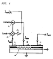
- the exemplary feedback control circuit shown in FIG. 1 uses no external optics.
- An error signal is derived from a photodetector integrated with the laser. The photodetector measures the light transmitted though the Bragg section of the laser, that is, the back facet light output of the laser. The error signal is used to control the current supplied to the Bragg section of the laser.
- the period of the Bragg grating is adjusted causing the Bragg wavelength to coincide with a predetermined longitudinal or Fabry-Perot mode of the laser.
- the laser output exhibits a maximum sidemode suppression ratio.
- FIG. 1 shows a simplified schematic diagram of a tunable, multi-section distributed Bragg reflector laser together with an exemplary feedback control circuit.
- the distributed Bragg reflector laser includes Bragg section 10, gain section 11, and integrated photodiode section 14.
- Bragg section 10 includes diffraction grating (Bragg grating) 16 and metallic contact 12.
- Gain section 13 employs a multiple quantum well stack in the active region which is controlled via contact 13. Detected photocurrent is output by photodiode 14 via contact 15. Details concerning the realization and fabrication of this type of tunable distributed Bragg reflector laser are well known in the art and have been described in Applied Physics Letters , Vol. 58, pp. 1239-40 (1991).
- the current to the Bragg section (I dbr ) is biased so that the feedback operation cannot inadvertently reverse bias the Bragg section of the laser.
- a high speed dither signal is applied by oscillator 21 to lock-in amplifier circuit element 20.
- the high speed dither signal is combined with the detected photocurrent (I det ) from photodiode 14 to permit detection by the lock-in amplifier. Following detection, this signal is amplified and fed back to the Bragg section as an element of the applied Bragg current.
- the dc bias of the Bragg section is supplied as current I dbr,DC .
- the operation of the circuit is as follows.
- a small ac current approximately 0.2mA (peak-to-peak) at a frequency of approximately 100kHz from oscillator 21, is applied to the Bragg section of the laser.
- the output power is Bragg section 10 is detected by the integrated photodiode 14.
- the signal from the photodiode is applied directly to lock-in amplifier element 20.
- the first derivative of the light output with respect to the current applied to the Bragg section (I dbr ) is obtained by detecting the 100kHz component of the output power using lock-in amplifier element 20.
- the means for measuring at least one characteristic of the light output from the Bragg section of the laser comprises photodiode 14 and lock-in amplifier element 20.
- the amplifier output is fed back to the Bragg section of the laser thereby closing the feedback loop.
- the feedback means comprises lock-in amplifier 20, amplifier 22, and oscillator 21. Operation and construction on the individual components of the feedback control circuit are known and understood by those skilled in the art and are not discussed below in further detail.
- FIG. 2 shows an exemplary plot of the variation of the Bragg wavelength as a function of the Bragg current.
- the Bragg wavelength is a center wavelength for the reflectivity characteristic of Bragg grating 16.
- One such reflectivity characteristic is shown in FIG. 3 as curve 300.
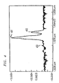
- the sidemode suppression ratio is maximum when the desired longitudinal mode of the laser is at or near the center of the Bragg reflectivity characteristic or Bragg band. It can be seen in FIG. 3 that this occurs when the main mode is at the Bragg wavelength corresponding to point 301 on the reflectivity characteristic and when the side longitudinal modes are at wavelengths corresponding to points 302 and 303 on the reflectivity characteristic. As shown in FIG. 5, the main longitudinal mode 501 far exceeds side longitudinal modes 502 and 503, both of which appear with substantially equal power levels. In contrast, the sidemode suppression ratio for the laser is degraded when the main longitudinal mode is not centered at the Bragg wavelength. This condition is shown by points 301', 302', and 303' on the reflectivity characteristic curve 300. The degraded sidemode suppression ratio is further shown in FIG. 4 wherein output spectra 400 shows a main longitudinal mode 401 and an extremely high side longitudinal mode 402. This imbalance of mode powers seriously degrades the sidemode suppression ratio of the laser.
- the reflectivity of grating 16 in the Bragg section is a maximum at the Bragg wavelength so that, when operating at the Bragg wavelength, a smaller fraction of light is transmitted through the Bragg section toward photodiode 14.
- the feedback control circuit shown in FIG. 1 adjusts the Bragg section current in a controllable manner so that the amount of light transmitted through the Bragg section is minimized which, in turn, causes the desired operating wavelength of the laser to be simultaneously adjusted close to the center of the Bragg band at or near the Bragg wavelength.
- the sidemode suppression ratio of the laser approaches its maximum.
- the dc bias of the laser was set to approximately 10mA resulting in a sidemode suppression ratio of 36.6dB for a desired operating wavelength at 1.528 m without any feedback control.
- the Bragg section current changed to 14.7mA. This corresponded to a point where the light detected by photodiode 14 was minimized.
- the sidemode suppression ratio at this Bragg section current rose to 53.2dB.
- the operating wavelength of the laser was shifted by 0.6 ⁇ . This type of operation with the feedback control circuit on and off is exemplified in FIG. 3 by the viewing the modes being pulled to positions 301, 302, and 303 in the Bragg band where the main longitudinal mode of the laser is a point 301.
- the strength of the grating relative to the strength of the facet reflector on the active or gain section of the laser is believed to affect the performance of the mode stabilization apparatus.
- the lock-in amplifier will be unable to detect any points where the first derivative of I det is zero.
- FIG. 7 One particular example fitting there conditions occurred in experimental practice and is shown in FIG. 7.
- the grating strength of Bragg grating 16 was kL dbr ⁇ 1. It can be seen from curve 701 that the current from photodiode 14 does not have a point at which its first derivative is equal to zero. As such, the feedback control circuit is unable to find a suitable wavelength on which to lock.
- the example depicted in FIG. 6 is for a moderately strong grating where kL dbr is approximately greater than 1 (for the example in FIG. 6, the grating strength is approximately 1.3) and where the facet reflectivity is approximately 32%.
- the mirror losses are dominated by the front facet and tuning of the grating has negligible effect on the total mirror loss.
- Output power of the laser does not depend strongly on the tuning operation.
- the desired operating wavelength of the laser is simultaneously adjusted to be close to the center of the Bragg band, that is, at or near the Bragg wavelength. This implies that the sidemode suppression ratio of the laser is close to a maxumium.
- minima that is, points at which the first derivative are zero, for curve 601 corresponds to maxima for the sidemode suppression ratio.
Applications Claiming Priority (2)
| Application Number | Priority Date | Filing Date | Title |
|---|---|---|---|
| US07/786,480 US5220578A (en) | 1991-11-01 | 1991-11-01 | Long term mode stabilization for distributed bragg reflector laser |
| US786480 | 1991-11-01 |
Publications (2)
| Publication Number | Publication Date |
|---|---|
| EP0545534A1 true EP0545534A1 (fr) | 1993-06-09 |
| EP0545534B1 EP0545534B1 (fr) | 1998-06-17 |
Family
ID=25138721
Family Applications (1)
| Application Number | Title | Priority Date | Filing Date |
|---|---|---|---|
| EP92309618A Expired - Lifetime EP0545534B1 (fr) | 1991-11-01 | 1992-10-21 | Stabilisation à long terme du mode d'un laser de type réflecteur de Bragg distribué |
Country Status (3)
| Country | Link |
|---|---|
| US (1) | US5220578A (fr) |
| EP (1) | EP0545534B1 (fr) |
| JP (1) | JPH06291403A (fr) |
Cited By (6)
| Publication number | Priority date | Publication date | Assignee | Title |
|---|---|---|---|---|
| WO2001076028A1 (fr) * | 2000-04-05 | 2001-10-11 | Altitun Ab | Procede de stabilisation de la frequence et du mode d'un laser accordable |
| EP1195861A2 (fr) * | 2000-09-22 | 2002-04-10 | Agere Systems Optoelectronics Guardian Corporation | Vieillissement dans lasers à semi-conducteur accordables |
| WO2003088438A2 (fr) * | 2002-04-18 | 2003-10-23 | Alcatel | Procede de stabilisation pour source laser a reflecteur distribue |
| US6826206B1 (en) | 1999-02-17 | 2004-11-30 | Adc Telecommunications, Inc. | Method of characterizing a tuneable laser |
| WO2005101596A1 (fr) * | 2004-04-15 | 2005-10-27 | Cambridge University Technical Services | Controle de la longueur d'ondes d'une lumiere laser |
| GB2554652B (en) * | 2016-09-30 | 2022-08-10 | Lumentum Tech Uk Limited | Active mode centre control |
Families Citing this family (13)
| Publication number | Priority date | Publication date | Assignee | Title |
|---|---|---|---|---|
| US5418802A (en) * | 1993-11-12 | 1995-05-23 | Eastman Kodak Company | Frequency tunable waveguide extended cavity laser |
| US6222861B1 (en) * | 1998-09-03 | 2001-04-24 | Photonic Solutions, Inc. | Method and apparatus for controlling the wavelength of a laser |
| US6327402B1 (en) | 1999-02-04 | 2001-12-04 | Lucent Technologies, Inc. | Lightwave transmission system having wide pump wavebands |
| US6064681A (en) * | 1999-06-11 | 2000-05-16 | Lucent Technologies Inc. | Wavelength stabilized, tunable optical transmitter with high SMSR |
| JP2002043698A (ja) * | 1999-12-22 | 2002-02-08 | Yokogawa Electric Corp | Shgレーザ光源及びshgレーザ光源の変調方法 |
| US6993050B2 (en) | 2001-03-14 | 2006-01-31 | At&T Corp. | Transmit and receive system for cable data service |
| GB0124217D0 (en) * | 2001-10-09 | 2001-11-28 | Denselight Semiconductors Pte | Two-section distributed bragg reflector laser |
| US7242701B2 (en) * | 2005-02-15 | 2007-07-10 | Lucent Technologies Inc. | Laser wavelength control arrangement and method |
| US7483458B2 (en) * | 2006-10-16 | 2009-01-27 | Corning Incorporated | Wavelength control in semiconductor lasers |
| US7586960B2 (en) * | 2007-01-23 | 2009-09-08 | Corning Incorporated | Forced wavelength chirping in semiconductor lasers |
| US7505492B2 (en) * | 2007-05-11 | 2009-03-17 | Corning Incorporated | Alignment of lasing wavelength with wavelength conversion peak using modulated wavelength control signal |
| US8204091B2 (en) * | 2008-07-03 | 2012-06-19 | Corning Incorporated | Wavelength normalization in phase section of semiconductor lasers |
| US20160134080A1 (en) * | 2014-11-10 | 2016-05-12 | Pd-Ld, Inc. | Single longitudinal mode laser diode system |
Family Cites Families (3)
| Publication number | Priority date | Publication date | Assignee | Title |
|---|---|---|---|---|
| US4785454A (en) * | 1983-05-13 | 1988-11-15 | American Telephone And Telegraph Company, At&T Bell Laboratories | Stabilized cleaved-coupled cavity laser |
| JP2532632B2 (ja) * | 1988-12-23 | 1996-09-11 | 松下電器産業株式会社 | 半導体レ―ザ装置と半導体光検出器及びその製造方法 |
| CA2018928C (fr) * | 1989-06-14 | 1994-07-26 | Akihiko Oka | Laser a semiconducteur |
-
1991
- 1991-11-01 US US07/786,480 patent/US5220578A/en not_active Expired - Lifetime
-
1992
- 1992-10-21 EP EP92309618A patent/EP0545534B1/fr not_active Expired - Lifetime
- 1992-11-02 JP JP4315629A patent/JPH06291403A/ja active Pending
Non-Patent Citations (7)
| Title |
|---|
| IEEE PHOTONICS TECHNOLOGY LETTERS vol. 1, no. 12, December 1989, NEW YORK US pages 452 - 454 OSAMU ISHIDA ET AL. '0.04 Hz relative optical-frequency stability in a 1.5mum distributed-bragg-reflector (DBR) laser' * |
| IEEE PHOTONICS TECHNOLOGY LETTERS vol. 2, no. 1, January 1990, NEW YORK US pages 63 - 65 C.R. GILES ET AL. 'Method for setting the absolute frequency of a tunable, 1.5 mum two-section DBR laser' * |
| IEEE PHOTONICS TECHNOLOGY LETTERS vol. 2, no. 12, December 1990, NEW YORK US pages 854 - 856 S.L. WOODWARD ET AL. 'The side-mode-suppression ratio of a tunable DBR laser' * |
| IEEE PHOTONICS TECHNOLOGY LETTERS vol. 4, no. 5, May 1992, NEW YORK US pages 417 - 419 S.L. WOODWARD ET AL. 'A control loop which ensures high side-mode-suppression ratio in a tunable DBR laser' * |
| JOURNAL OF LIGHTWAVE TECHNOLOGY. vol. 2, no. 1, 1 February 1984, NEW YORK US pages 49 - 51 N. ANDERS OLSSON ET AL. 'Active spectral stabilization of cleaved-coupled-cavity (C3) lasers' * |
| PATENT ABSTRACTS OF JAPAN vol. 12, no. 348 (E-659)19 September 1988 & JP-A-63 104 492 ( NEC CORP. ) * |
| PATENT ABSTRACTS OF JAPAN vol. 7, no. 36 (E-158)(1181) 15 February 1983 & JP-A-57 190 384 ( TOKYO SHIBAURA DENKI K.K. ) * |
Cited By (11)
| Publication number | Priority date | Publication date | Assignee | Title |
|---|---|---|---|---|
| US6826206B1 (en) | 1999-02-17 | 2004-11-30 | Adc Telecommunications, Inc. | Method of characterizing a tuneable laser |
| WO2001076028A1 (fr) * | 2000-04-05 | 2001-10-11 | Altitun Ab | Procede de stabilisation de la frequence et du mode d'un laser accordable |
| US6888858B2 (en) | 2000-04-05 | 2005-05-03 | Adc Telecommunications, Inc. | Method for frequency and mode stabilization of a tuneable laser |
| EP1195861A2 (fr) * | 2000-09-22 | 2002-04-10 | Agere Systems Optoelectronics Guardian Corporation | Vieillissement dans lasers à semi-conducteur accordables |
| EP1195861A3 (fr) * | 2000-09-22 | 2005-01-05 | TriQuint Technology Holding Co | Vieillissement dans lasers à semi-conducteur accordables |
| WO2003088438A2 (fr) * | 2002-04-18 | 2003-10-23 | Alcatel | Procede de stabilisation pour source laser a reflecteur distribue |
| FR2838877A1 (fr) * | 2002-04-18 | 2003-10-24 | Cit Alcatel | Procede de stabilisation pour source laser a reflecteur distribue |
| EP1363366A1 (fr) * | 2002-04-18 | 2003-11-19 | Alcatel | Procedé de stabilisation pour source laser à reflecteur distribué |
| WO2003088438A3 (fr) * | 2002-04-18 | 2004-05-13 | Cit Alcatel | Procede de stabilisation pour source laser a reflecteur distribue |
| WO2005101596A1 (fr) * | 2004-04-15 | 2005-10-27 | Cambridge University Technical Services | Controle de la longueur d'ondes d'une lumiere laser |
| GB2554652B (en) * | 2016-09-30 | 2022-08-10 | Lumentum Tech Uk Limited | Active mode centre control |
Also Published As
| Publication number | Publication date |
|---|---|
| JPH06291403A (ja) | 1994-10-18 |
| EP0545534B1 (fr) | 1998-06-17 |
| US5220578A (en) | 1993-06-15 |
Similar Documents
| Publication | Publication Date | Title |
|---|---|---|
| EP0545534B1 (fr) | Stabilisation à long terme du mode d'un laser de type réflecteur de Bragg distribué | |
| EP1059745B1 (fr) | Emetteur optique accordable stabilisé en longueur d'onde à rapport de suppression des modes latèrales élevé | |
| US6371662B1 (en) | Spatially variable filter laser wavelength monitoring/control | |
| US4622672A (en) | Self-stabilized semiconductor lasers | |
| US7505490B2 (en) | Phase-control in an external-cavity tuneable laser | |
| US6928092B2 (en) | Method and apparatus for active numeric temperature compensation of an etalon in a wavelength stabilized laser | |
| US5943152A (en) | Laser wavelength control device | |
| US4926429A (en) | Lightwave communication system having sources independently synchronized to an absolute frequency standard | |
| WO1984000857A1 (fr) | Laser stabilise spectralement | |
| US7209498B1 (en) | Method and apparatus for tuning a laser | |
| US6518563B1 (en) | Detecting aging of optical components | |
| WO2005091451A1 (fr) | Etalonnage, controle et commande d'un laser | |
| Jang et al. | A cold-start WDM system using a synchronized etalon filter | |
| US6327064B1 (en) | Frequency stabilized and crosstalk-free signal sources for optical communication systems | |
| US6804273B1 (en) | Method and system for compensating a frequency stabilized optical source | |
| JP2003218461A (ja) | Wdm光通信システムにおける光チャネルの波長/光出力の安定化方法及びそのシステム | |
| JP3237499B2 (ja) | 周波数安定化光源 | |
| GB2380058A (en) | Telecommunication laser transmitter systems and methods of operating such systems | |
| Nielsen et al. | Linewidth stabilization of semiconductor lasers in an external cavity | |
| Ackerman et al. | Wavelength, modal and power stabilization of tunable electro-absorption modulated, distributed Bragg reflector lasers | |
| KR19990001406A (ko) | 파장 분할 다중방식 광전송 시스템을 위한 광원 안정화 시스템 | |
| DeCusatis et al. | Wavelength locked loops for optical communication networks | |
| Seeds et al. | Advanced techniques for the optical generation of microwave signals | |
| GB2382461A (en) | A coolerless fixed wavelength laser diode | |
| KR20060067971A (ko) | 외부공동 가변파장 레이저에서의 위상제어 |
Legal Events
| Date | Code | Title | Description |
|---|---|---|---|
| PUAI | Public reference made under article 153(3) epc to a published international application that has entered the european phase |
Free format text: ORIGINAL CODE: 0009012 |
|
| AK | Designated contracting states |
Kind code of ref document: A1 Designated state(s): FR GB |
|
| 17P | Request for examination filed |
Effective date: 19931125 |
|
| RAP3 | Party data changed (applicant data changed or rights of an application transferred) |
Owner name: AT&T CORP. |
|
| 17Q | First examination report despatched |
Effective date: 19961212 |
|
| GRAG | Despatch of communication of intention to grant |
Free format text: ORIGINAL CODE: EPIDOS AGRA |
|
| GRAG | Despatch of communication of intention to grant |
Free format text: ORIGINAL CODE: EPIDOS AGRA |
|
| GRAH | Despatch of communication of intention to grant a patent |
Free format text: ORIGINAL CODE: EPIDOS IGRA |
|
| GRAH | Despatch of communication of intention to grant a patent |
Free format text: ORIGINAL CODE: EPIDOS IGRA |
|
| GRAA | (expected) grant |
Free format text: ORIGINAL CODE: 0009210 |
|
| AK | Designated contracting states |
Kind code of ref document: B1 Designated state(s): FR GB |
|
| ET | Fr: translation filed | ||
| PLBE | No opposition filed within time limit |
Free format text: ORIGINAL CODE: 0009261 |
|
| STAA | Information on the status of an ep patent application or granted ep patent |
Free format text: STATUS: NO OPPOSITION FILED WITHIN TIME LIMIT |
|
| 26N | No opposition filed | ||
| REG | Reference to a national code |
Ref country code: GB Ref legal event code: IF02 |
|
| PGFP | Annual fee paid to national office [announced via postgrant information from national office to epo] |
Ref country code: GB Payment date: 20101021 Year of fee payment: 19 |
|
| PGFP | Annual fee paid to national office [announced via postgrant information from national office to epo] |
Ref country code: FR Payment date: 20111103 Year of fee payment: 20 |
|
| REG | Reference to a national code |
Ref country code: GB Ref legal event code: PE20 Expiry date: 20121020 |
|
| PG25 | Lapsed in a contracting state [announced via postgrant information from national office to epo] |
Ref country code: GB Free format text: LAPSE BECAUSE OF EXPIRATION OF PROTECTION Effective date: 20121020 |