US4622672A - Self-stabilized semiconductor lasers - Google Patents
Self-stabilized semiconductor lasers Download PDFInfo
- Publication number
- US4622672A US4622672A US06/572,682 US57268284A US4622672A US 4622672 A US4622672 A US 4622672A US 57268284 A US57268284 A US 57268284A US 4622672 A US4622672 A US 4622672A
- Authority
- US
- United States
- Prior art keywords
- laser
- cavity
- etalon
- recited
- current
- Prior art date
- Legal status (The legal status is an assumption and is not a legal conclusion. Google has not performed a legal analysis and makes no representation as to the accuracy of the status listed.)
- Expired - Fee Related
Links
Images
Classifications
-
- H—ELECTRICITY
- H01—ELECTRIC ELEMENTS
- H01S—DEVICES USING THE PROCESS OF LIGHT AMPLIFICATION BY STIMULATED EMISSION OF RADIATION [LASER] TO AMPLIFY OR GENERATE LIGHT; DEVICES USING STIMULATED EMISSION OF ELECTROMAGNETIC RADIATION IN WAVE RANGES OTHER THAN OPTICAL
- H01S5/00—Semiconductor lasers
- H01S5/10—Construction or shape of the optical resonator, e.g. extended or external cavity, coupled cavities, bent-guide, varying width, thickness or composition of the active region
- H01S5/1021—Coupled cavities
-
- H—ELECTRICITY
- H01—ELECTRIC ELEMENTS
- H01S—DEVICES USING THE PROCESS OF LIGHT AMPLIFICATION BY STIMULATED EMISSION OF RADIATION [LASER] TO AMPLIFY OR GENERATE LIGHT; DEVICES USING STIMULATED EMISSION OF ELECTROMAGNETIC RADIATION IN WAVE RANGES OTHER THAN OPTICAL
- H01S5/00—Semiconductor lasers
- H01S5/0014—Measuring characteristics or properties thereof
- H01S5/0028—Laser diodes used as detectors
-
- H—ELECTRICITY
- H01—ELECTRIC ELEMENTS
- H01S—DEVICES USING THE PROCESS OF LIGHT AMPLIFICATION BY STIMULATED EMISSION OF RADIATION [LASER] TO AMPLIFY OR GENERATE LIGHT; DEVICES USING STIMULATED EMISSION OF ELECTROMAGNETIC RADIATION IN WAVE RANGES OTHER THAN OPTICAL
- H01S5/00—Semiconductor lasers
- H01S5/06—Arrangements for controlling the laser output parameters, e.g. by operating on the active medium
- H01S5/068—Stabilisation of laser output parameters
- H01S5/06808—Stabilisation of laser output parameters by monitoring the electrical laser parameters, e.g. voltage or current
-
- H—ELECTRICITY
- H01—ELECTRIC ELEMENTS
- H01S—DEVICES USING THE PROCESS OF LIGHT AMPLIFICATION BY STIMULATED EMISSION OF RADIATION [LASER] TO AMPLIFY OR GENERATE LIGHT; DEVICES USING STIMULATED EMISSION OF ELECTROMAGNETIC RADIATION IN WAVE RANGES OTHER THAN OPTICAL
- H01S5/00—Semiconductor lasers
- H01S5/06—Arrangements for controlling the laser output parameters, e.g. by operating on the active medium
- H01S5/068—Stabilisation of laser output parameters
- H01S5/0683—Stabilisation of laser output parameters by monitoring the optical output parameters
- H01S5/0687—Stabilising the frequency of the laser
Definitions
- This invention relates generally to semiconductor lasers and particularly to such lasers that operate stably with a single longitudinal mode output.
- Optical communications systems as presently contemplated and constructed use a light source, such as a semiconductor laser or light emitting diode, which is optically coupled to a photodetector through a glass transmission line.
- the transmission line is commonly referred to as an "optical fiber.”
- Either amplitude or frequency modulation may be used to convey information. If amplitude modulation is used, the information is transmitted as a bit stream of 1's and 0's with the bits being both transmitted and detected within predetermined time intervals.
- Such systems presently operate at wavelengths between approximately 0.8 ⁇ m and approximately 1.6 ⁇ m with the longer wavelengths, that is, the wavelengths greater than appoximately 1.2 ⁇ m, presently being considered most desirable for many systems applications because optical fibers presently used exhibit minimum loss and dispersion within this wavelength range. These characteristics facilitate design of optical communications systems having desirable properties such as high transmission rates, long distances between repeaters. etc.
- the light source should not only emit radiation within this wavelength range but should also have its output concentrated in a narrow spectral range.
- the light source should be a semiconductor laser emitting output of a single longitudinal mode.
- a single longitudinal mode is narrow enough in spectral width that it may be thought of as being a single frequency.
- the output contains unwanted secondary modes but these are greatly suppressed in intensity with respect to the wanted primary mode.
- the requirement that the output be a single longitudinal mode is easily understood by considering that a finite width pulse will spread, i.e., broaden, because of the dispersion properties of the fiber. If the spread becomes large enough, adjacent pulses will overlap and recovery of the transmitted information by the receiver will be impossible; i.e., the bits will not arrive at the photodetector within the proper time interval.
- DFB distributed feedback
- Semiconductor lasers operating with an external cavity to produce single mode operation have been reported.
- coupled cavity lasers have been developed and have been shown to produce single longitudinal mode output even under high speed modulation. See for example, Electronics Letters, 18, pp. 901-902, Oct. 14, 1982, and Applied Physics Letters, 42, pp. 650-652, Apr. 15, 1983.
- a coupled cavity laser has two cavities which are optically coupled to each other. Each cavity has separate electrical contacts, i.e., the laser is a three-terminal device. One cavity operates as an oscillator while the other cavity acts as an etalon and provides mode selection. That the laser produces a single mode output is understood, for the case of gap widths approximately n ⁇ /2, where n is an integer and ⁇ is the wavelength of the radiation, by considering that the mode of the coupled cavity laser must satisfy Fabry-Perot mode conditions in both cavities.
- modes are enhanced at local loss minima because of the constructive interference of optical energy reflected from the gap with that fed back from the other cavity, i.e., the etalon. This may occur near resonance or anti-resonance of the etalon as well as intermediate points. This is possible only for a limited number of discrete frequencies.
- Variation of the etalon current permits tuning of the wavelength across the gain profile of the laser.
- a large number of mode hops may occur as the etalon current is increased from zero to values above threshold.
- the mode hop boundaries as a function of etalon current, vary with temperature and also perhaps with device aging.
- Mode hops are undesirable because they may cause information to be lost because, for example, bits are not transmitted as desired or they are lost because they are not received within the proper time interval.
- techniques to maintain single mode operation at a desired wavelength are desirable.
- Wavelength stabilization techniques have been previously developed for both coupled cavity lasers as well as various other types of lasers such as semiconductor lasers operating with an external cavity.
- a common element of these prior art schemes is the requirement of an external optical element, such as either a photodetector or a spectrometer, to monitor the light output from, e.g., the laser.
- Feedback loops are then used to adjust, for example, the laser current or a property of the external cavity such as its length if it is a passive cavity.
- wavelength stabilization of a semiconductor laser having two cavities optically coupled to each other may be obtained by using the lasing cavity as a photodetector to provide a discrimination signal for a feedback control circuit.
- the feedback control circuit comprises means for measuring the voltage variation across the laser cavity, means for comparing the measured voltage to a reference characteristic, and means for varying a property of a second cavity by an amount determined by said comparing step.
- the laser is a coupled cavity laser and the circuit comprises a dc blocking circuit, a phase-sensitive detector which is electrically connected to the laser cavity, and a reference oscillator electrically connected to both the blocking circuit and the phase-sensitive detector.
- the output from the phase-sensitive detector goes to an amplifier where it is compared to a reference value.
- the outputs from the amplifier which is a function of the difference between the measured and references voltages, and blocking circuit are superimposed on the etalon current.
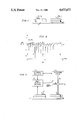
- FIG. 1 is a schematic representation of a coupled cavity semiconductor laser
- FIG. 2 plots a typical differential voltage (laser)/current (etalon) characteristic, i.e., dV L /dI E , vertically versus the etalon current horizontally in units of mA; and
- FIG. 3 is a schematic representation of a wavelength stabilized coupled cavity semiconductor laser according to our invention.
- the laser comprises laser cavity 1, etalon 3, electrode 5, laser electrode 7, and etalon electrode 9.
- Electrode 5 is a common electrode and contacts both the laser cavity and the etalon. Both cavities comprise a narrow active stripe 11 where electron hole recombination takes place when the laser cavity and etalon are forward biased.
- the laser and etalon cavities are spaced from each other but are optically coupled to each other. The space between the cavities may be formed by, for example, etching or cleaving a unitary structure.
- the details of exemplary laser and etalon cavities, as well as their fabrication, are well known to those skilled in the art and need not be further described in detail.
- control circuit will be better understood if the operation and light output characteristics of the coupled cavity laser are first explained by assuming that a constant current, I L , which is above threshold, flows through the lasing section. If the magnitude of the etalon current is now varied, the changes, dI E , of the etalon current cause variations of the light distribution within the coupled cavity system. These variations also lead to variations, dV L , of the lasing junction voltage as a consequence of the internal photoeffect. These variations are typically extremely small.
- FIG. 2 shows a typical differential signal, dV L /dI E , plotted vertically in arbitrary units as a function of the etalon current plotted horizontally in units of mA.
- the laser was an InGaAsP/InP buried crescent coupled cavity laser emitting at 1.3 ⁇ m. The lengths of the two cavities were 222.0 and 191.0 ⁇ m and the space between them was less than 1.0 ⁇ m. The current through the lasing section was 20 mA above threshold. The laser produces stable single mode output when the etalon current is above 3 mA.
- the etalon current increases, mode hops occur to neighboring modes as well as across the entire gain profile of the semiconductor laser.
- the arrows indicate mode hops across the entire gain profile. It was found that a mode hop results in a sudden decrease in the differential signal with an abrupt mode hop producing a sharp negative peak while a more gradual mode transition produces a comparatively smooth step. Between successive mode transitions, the differential signal usually increases as the etalon current increases.
- the behavior of the junction voltage, V L is a function of the etalon current, I E , and may be used to detect mode hopping.
- the points of maximum suppression, with respect to the primary mode, of the unwanted secondary modes are indicated by the solid circles. These circles generally lie approximately in the center of each single mode regime.
- the dV L /dI E slope may therefore be used as a discriminating signal.
- the wavelength stabilization circuit of this invention tracks the etalon current to the point of optimum mode suppression and maintains the current at that point by adding the amplified discriminating signal to the preset etalon bias current. If the etalon current is preset before the feedback loop is turned on, the desired mode can be maintained.
- FIG. 3 is a schematic representation of our wavelength stabilization circuit.
- the stabilization circuit further comprises a phase-sensitive detector 31, a reference oscillator 33, a dc blocking circuit 35, and an amplifier 37.
- the output from the reference oscillator goes to both the dc blocking circuit and the phase-sensitive detector.
- the phase-sensitive detector is connected to the laser cavity and to an amplifier which also has a reference input, ⁇ ref .
- the amplifier output is a function of the difference between the signal from the phase-sensitive detector and ⁇ ref .
- the output of the amplifier, dc blocking circuit, and the etalon current, I E are combined and sent to the etalon cavity.
- Each of these elements is well known to those skilled in the art and need not be described in further detail.
- the laser cavity is driven above threshold and a small dither signal from the dc blocking circuit is superimposed on the etalon current.
- a typical amplitude is 10 ⁇ A and a typical frequency is 1 kHz.
- the corresponding ac voltage change at the lasing cavity is detected with the phase-sensitive detector. If the measured ac signal deviates from a reference value, indicated as ⁇ ref , required for optimum suppression of the unwanted secondary modes, a dc correction current is fed from the amplifier to the etalon thereby forcing the overall etalon current to the optimum value.
- the temperature was then varied and the output spectra recorded. With the wavelength control circuit on, the emission stayed in the same mode over the temperature range between 14 degrees C. and 26 degrees C. while several mode hops occurred with the circuit off.
- our circuit may be used with other types of lasers.
- the feedback circuit may be used to adjust the length of the external cavity used with a semiconductor laser.
Abstract
Description
Claims (12)
Priority Applications (1)
| Application Number | Priority Date | Filing Date | Title |
|---|---|---|---|
| US06/572,682 US4622672A (en) | 1984-01-20 | 1984-01-20 | Self-stabilized semiconductor lasers |
Applications Claiming Priority (1)
| Application Number | Priority Date | Filing Date | Title |
|---|---|---|---|
| US06/572,682 US4622672A (en) | 1984-01-20 | 1984-01-20 | Self-stabilized semiconductor lasers |
Publications (1)
| Publication Number | Publication Date |
|---|---|
| US4622672A true US4622672A (en) | 1986-11-11 |
Family
ID=24288895
Family Applications (1)
| Application Number | Title | Priority Date | Filing Date |
|---|---|---|---|
| US06/572,682 Expired - Fee Related US4622672A (en) | 1984-01-20 | 1984-01-20 | Self-stabilized semiconductor lasers |
Country Status (1)
| Country | Link |
|---|---|
| US (1) | US4622672A (en) |
Cited By (37)
| Publication number | Priority date | Publication date | Assignee | Title |
|---|---|---|---|---|
| US4807992A (en) * | 1986-02-24 | 1989-02-28 | Fuji Photo Film Co., Ltd. | Method of detecting semiconductor laser mode hopping and semiconductor laser beam source apparatus |
| US4873989A (en) * | 1984-03-08 | 1989-10-17 | Optical Technologies, Inc. | Fluid flow sensing apparatus for in vivo and industrial applications employing novel optical fiber pressure sensors |
| WO1991006141A1 (en) * | 1989-10-13 | 1991-05-02 | Hans Martin | Apparatus for stabilizing the wavelength of a signal-modulated light beam |
| US5161165A (en) * | 1991-09-26 | 1992-11-03 | Hewlett-Packard Company | Multimode stabilized external cavity laser |
| US5222070A (en) * | 1990-12-12 | 1993-06-22 | Advantest Corporation | Optical pulse oscillator and light frequency measuring apparatus using the same |
| US5629954A (en) * | 1994-10-25 | 1997-05-13 | Trw Inc. | Semiconductor laser diode with integrated etalon |
| US5646763A (en) * | 1994-12-20 | 1997-07-08 | Fujitsu Limited | Optical transmitter and laser diode module for use in the optical transmitter |
| US6222860B1 (en) * | 1999-01-07 | 2001-04-24 | Hewlett-Packard Company | Laser system tolerating disturbances using multiple modes |
| WO2002003515A2 (en) * | 2000-06-29 | 2002-01-10 | Agility Communications, Inc. | Gain voltage control of sampled grating distributed bragg reflector lasers |
| US20020061047A1 (en) * | 2000-06-09 | 2002-05-23 | Fish Gregory A. | Manufacturable sampled grating mirrors |
| WO2002093701A1 (en) * | 2001-05-15 | 2002-11-21 | Agility Communications, Inc. | Controller calibration for small form factor sampled grating distributed bragg reflector laser |
| WO2002093695A2 (en) * | 2001-05-15 | 2002-11-21 | Agility Communications, Inc. | Sampled grating distributed bragg reflector laser controller |
| US6590924B2 (en) | 2000-05-04 | 2003-07-08 | Agility Communications, Inc. | Mirror and cavity designs for sampled grating distributed bragg reflector lasers |
| US20030156611A1 (en) * | 2002-02-21 | 2003-08-21 | Hoki Kwon | GaAs/Al(Ga)As distributed bragg reflector on InP |
| US6690693B1 (en) | 2000-05-04 | 2004-02-10 | Agility Communications, Inc. | Power and wavelength control of sampled grating distributed Bragg reflector lasers |
| US6747742B1 (en) * | 2001-06-22 | 2004-06-08 | Tanner Research, Inc. | Microspectrometer based on a tunable fabry-perot interferometer and microsphere cavities |
| US6788719B2 (en) | 2000-05-04 | 2004-09-07 | Agility Communications, Inc. | Open loop control of SGDBR lasers |
| US20050094680A1 (en) * | 2003-10-30 | 2005-05-05 | Fujitsu Limited | Wavelength tunable laser and method of controlling the same |
| US20050100065A1 (en) * | 2000-06-29 | 2005-05-12 | Coldren Larry A. | Controller calibration for small form factor sampled grating distributed bragg reflector laser |
| US20050123015A1 (en) * | 1998-12-21 | 2005-06-09 | Johnson Ralph H. | Use of GaAs extended barrier layers between active regions containing nitrogen and AlGaAs confining layers |
| US20050129078A1 (en) * | 1998-12-21 | 2005-06-16 | Johnson Ralph H. | Multicomponent barrier layers in quantum well active regions to enhance confinement and speed |
| US6909734B2 (en) | 1999-09-02 | 2005-06-21 | Agility Communications, Inc. | High-power, manufacturable sampled grating distributed Bragg reflector lasers |
| US20050142683A1 (en) * | 1998-12-21 | 2005-06-30 | Honeywell International | System for developing a nitrogen-containing active region |
| US6922426B2 (en) | 2001-12-20 | 2005-07-26 | Finisar Corporation | Vertical cavity surface emitting laser including indium in the active region |
| US6975660B2 (en) | 2001-12-27 | 2005-12-13 | Finisar Corporation | Vertical cavity surface emitting laser including indium and antimony in the active region |
| US7058112B2 (en) | 2001-12-27 | 2006-06-06 | Finisar Corporation | Indium free vertical cavity surface emitting laser |
| US7095770B2 (en) | 2001-12-20 | 2006-08-22 | Finisar Corporation | Vertical cavity surface emitting laser including indium, antimony and nitrogen in the active region |
| US20060246700A1 (en) * | 1998-12-21 | 2006-11-02 | Johnson Ralph H | Migration enhanced epitaxy fabrication of active regions having quantum wells |
| US7286585B2 (en) | 1998-12-21 | 2007-10-23 | Finisar Corporation | Low temperature grown layers with migration enhanced epitaxy adjacent to an InGaAsN(Sb) based active region |
| US7295586B2 (en) | 2002-02-21 | 2007-11-13 | Finisar Corporation | Carbon doped GaAsSb suitable for use in tunnel junctions of long-wavelength VCSELs |
| US7408964B2 (en) | 2001-12-20 | 2008-08-05 | Finisar Corporation | Vertical cavity surface emitting laser including indium and nitrogen in the active region |
| WO2010097751A3 (en) * | 2009-02-25 | 2010-11-04 | Philips Intellectual Property & Standards Gmbh | Output power stabilization for laser diodes using the photon-cooling dependent laser voltage |
| US20100303476A1 (en) * | 2009-05-28 | 2010-12-02 | Freedom Photonics, Llc | Monolithic widely-tunable coherent receiver |
| US8168456B2 (en) | 2004-10-01 | 2012-05-01 | Finisar Corporation | Vertical cavity surface emitting laser with undoped top mirror |
| US8451875B2 (en) | 2004-10-01 | 2013-05-28 | Finisar Corporation | Vertical cavity surface emitting laser having strain reduced quantum wells |
| US9344196B1 (en) | 2009-05-28 | 2016-05-17 | Freedom Photonics, Llc. | Integrated interferometric optical transmitter |
| US11251584B2 (en) | 2017-03-28 | 2022-02-15 | Freedom Photonics Llc | Tunable laser |
-
1984
- 1984-01-20 US US06/572,682 patent/US4622672A/en not_active Expired - Fee Related
Non-Patent Citations (10)
| Title |
|---|
| H. Kogelnik and C. V. Shank, "Stimulated Emission in a Periodic Structure", Applied Physics Letters, vol. 18, No. 4, (1971), pp. 152-154. |
| H. Kogelnik and C. V. Shank, Stimulated Emission in a Periodic Structure , Applied Physics Letters, vol. 18, No. 4, (1971), pp. 152 154. * |
| K. J. Ebeling, L. A. Coldren, B. I. Miller and J. A. Rentschler, "Generation of Single-Longitudinal-Mode Subnanosecond Light Pulses by High-Speed Current Modulation of Monolithic Two-Section Semiconductor Lasers", Electronics Letters, vol. 18, No. 21, (1982), pp. 901-902. |
| K. J. Ebeling, L. A. Coldren, B. I. Miller and J. A. Rentschler, Generation of Single Longitudinal Mode Subnanosecond Light Pulses by High Speed Current Modulation of Monolithic Two Section Semiconductor Lasers , Electronics Letters, vol. 18, No. 21, (1982), pp. 901 902. * |
| K. R. Preston, "Simple Spectral Control Technique for External Cavity Laser Transmitters", Electronics Letters, vol. 18, No. 25, (1982), pp. 1092-1094. |
| K. R. Preston, Simple Spectral Control Technique for External Cavity Laser Transmitters , Electronics Letters, vol. 18, No. 25, (1982), pp. 1092 1094. * |
| W. Bludau et al, "Characterization of Laser-to-Fiber Coupling Techniques by their Optical Feedback", Applied Optics, vol. 21, No. 11, Jun. 1982, pp. 1933-1939. |
| W. Bludau et al, Characterization of Laser to Fiber Coupling Techniques by their Optical Feedback , Applied Optics, vol. 21, No. 11, Jun. 1982, pp. 1933 1939. * |
| W. Tsang, N. A. Olsson and R. A. Logan, "High-Speed Direct Single-Frequency Modulation with Large Tuning Rate and Frequency Excursion in Cleaved-Coupled-Cavity Semiconductor Lasers", Applied Physics Letters, vol. 42, No. 8, (1983), pp. 650-652. |
| W. Tsang, N. A. Olsson and R. A. Logan, High Speed Direct Single Frequency Modulation with Large Tuning Rate and Frequency Excursion in Cleaved Coupled Cavity Semiconductor Lasers , Applied Physics Letters, vol. 42, No. 8, (1983), pp. 650 652. * |
Cited By (65)
| Publication number | Priority date | Publication date | Assignee | Title |
|---|---|---|---|---|
| US4873989A (en) * | 1984-03-08 | 1989-10-17 | Optical Technologies, Inc. | Fluid flow sensing apparatus for in vivo and industrial applications employing novel optical fiber pressure sensors |
| US4807992A (en) * | 1986-02-24 | 1989-02-28 | Fuji Photo Film Co., Ltd. | Method of detecting semiconductor laser mode hopping and semiconductor laser beam source apparatus |
| WO1991006141A1 (en) * | 1989-10-13 | 1991-05-02 | Hans Martin | Apparatus for stabilizing the wavelength of a signal-modulated light beam |
| US5222070A (en) * | 1990-12-12 | 1993-06-22 | Advantest Corporation | Optical pulse oscillator and light frequency measuring apparatus using the same |
| US5161165A (en) * | 1991-09-26 | 1992-11-03 | Hewlett-Packard Company | Multimode stabilized external cavity laser |
| US5629954A (en) * | 1994-10-25 | 1997-05-13 | Trw Inc. | Semiconductor laser diode with integrated etalon |
| US5646763A (en) * | 1994-12-20 | 1997-07-08 | Fujitsu Limited | Optical transmitter and laser diode module for use in the optical transmitter |
| US7286585B2 (en) | 1998-12-21 | 2007-10-23 | Finisar Corporation | Low temperature grown layers with migration enhanced epitaxy adjacent to an InGaAsN(Sb) based active region |
| US7435660B2 (en) | 1998-12-21 | 2008-10-14 | Finisar Corporation | Migration enhanced epitaxy fabrication of active regions having quantum wells |
| US7257143B2 (en) | 1998-12-21 | 2007-08-14 | Finisar Corporation | Multicomponent barrier layers in quantum well active regions to enhance confinement and speed |
| US20050129078A1 (en) * | 1998-12-21 | 2005-06-16 | Johnson Ralph H. | Multicomponent barrier layers in quantum well active regions to enhance confinement and speed |
| US20060246700A1 (en) * | 1998-12-21 | 2006-11-02 | Johnson Ralph H | Migration enhanced epitaxy fabrication of active regions having quantum wells |
| US7167495B2 (en) | 1998-12-21 | 2007-01-23 | Finisar Corporation | Use of GaAs extended barrier layers between active regions containing nitrogen and AlGaAs confining layers |
| US20050123015A1 (en) * | 1998-12-21 | 2005-06-09 | Johnson Ralph H. | Use of GaAs extended barrier layers between active regions containing nitrogen and AlGaAs confining layers |
| US7378680B2 (en) | 1998-12-21 | 2008-05-27 | Finisar Corporation | Migration enhanced epitaxy fabrication of quantum wells |
| US20050142683A1 (en) * | 1998-12-21 | 2005-06-30 | Honeywell International | System for developing a nitrogen-containing active region |
| US6222860B1 (en) * | 1999-01-07 | 2001-04-24 | Hewlett-Packard Company | Laser system tolerating disturbances using multiple modes |
| US6909734B2 (en) | 1999-09-02 | 2005-06-21 | Agility Communications, Inc. | High-power, manufacturable sampled grating distributed Bragg reflector lasers |
| US6788719B2 (en) | 2000-05-04 | 2004-09-07 | Agility Communications, Inc. | Open loop control of SGDBR lasers |
| US6690693B1 (en) | 2000-05-04 | 2004-02-10 | Agility Communications, Inc. | Power and wavelength control of sampled grating distributed Bragg reflector lasers |
| US6590924B2 (en) | 2000-05-04 | 2003-07-08 | Agility Communications, Inc. | Mirror and cavity designs for sampled grating distributed bragg reflector lasers |
| US20050265420A1 (en) * | 2000-06-09 | 2005-12-01 | Fish Gregory A | Manufacturable sampled grating mirrors |
| US6937638B2 (en) | 2000-06-09 | 2005-08-30 | Agility Communications, Inc. | Manufacturable sampled grating mirrors |
| US7643532B2 (en) | 2000-06-09 | 2010-01-05 | Jds Uniphase Corporation | Manufacturable sampled grating mirrors |
| US20020061047A1 (en) * | 2000-06-09 | 2002-05-23 | Fish Gregory A. | Manufacturable sampled grating mirrors |
| WO2002003515A3 (en) * | 2000-06-29 | 2002-04-18 | Agility Communications Inc | Gain voltage control of sampled grating distributed bragg reflector lasers |
| US20050100065A1 (en) * | 2000-06-29 | 2005-05-12 | Coldren Larry A. | Controller calibration for small form factor sampled grating distributed bragg reflector laser |
| US7061943B2 (en) | 2000-06-29 | 2006-06-13 | Agility Communications, Inc. | Controller calibration for small form factor sampled grating distributed Bragg reflector laser |
| WO2002003515A2 (en) * | 2000-06-29 | 2002-01-10 | Agility Communications, Inc. | Gain voltage control of sampled grating distributed bragg reflector lasers |
| US6954476B2 (en) | 2001-05-15 | 2005-10-11 | Agility Communications, Inc. | Sampled grating distributed Bragg reflector laser controller |
| US20040136423A1 (en) * | 2001-05-15 | 2004-07-15 | Coldren Larry A | Sampled grating distributed bragg reflector laser controller |
| WO2002093695A3 (en) * | 2001-05-15 | 2007-10-25 | Agility Communications Inc | Sampled grating distributed bragg reflector laser controller |
| WO2002093695A2 (en) * | 2001-05-15 | 2002-11-21 | Agility Communications, Inc. | Sampled grating distributed bragg reflector laser controller |
| WO2002093701A1 (en) * | 2001-05-15 | 2002-11-21 | Agility Communications, Inc. | Controller calibration for small form factor sampled grating distributed bragg reflector laser |
| US6747742B1 (en) * | 2001-06-22 | 2004-06-08 | Tanner Research, Inc. | Microspectrometer based on a tunable fabry-perot interferometer and microsphere cavities |
| US6922426B2 (en) | 2001-12-20 | 2005-07-26 | Finisar Corporation | Vertical cavity surface emitting laser including indium in the active region |
| US7408964B2 (en) | 2001-12-20 | 2008-08-05 | Finisar Corporation | Vertical cavity surface emitting laser including indium and nitrogen in the active region |
| US7095770B2 (en) | 2001-12-20 | 2006-08-22 | Finisar Corporation | Vertical cavity surface emitting laser including indium, antimony and nitrogen in the active region |
| US6975660B2 (en) | 2001-12-27 | 2005-12-13 | Finisar Corporation | Vertical cavity surface emitting laser including indium and antimony in the active region |
| US7058112B2 (en) | 2001-12-27 | 2006-06-06 | Finisar Corporation | Indium free vertical cavity surface emitting laser |
| US7295586B2 (en) | 2002-02-21 | 2007-11-13 | Finisar Corporation | Carbon doped GaAsSb suitable for use in tunnel junctions of long-wavelength VCSELs |
| US6822995B2 (en) | 2002-02-21 | 2004-11-23 | Finisar Corporation | GaAs/AI(Ga)As distributed bragg reflector on InP |
| US20030156611A1 (en) * | 2002-02-21 | 2003-08-21 | Hoki Kwon | GaAs/Al(Ga)As distributed bragg reflector on InP |
| JP4713073B2 (en) * | 2003-10-30 | 2011-06-29 | 富士通株式会社 | Tunable laser and control method thereof |
| JP2005136202A (en) * | 2003-10-30 | 2005-05-26 | Fujitsu Ltd | Variable wavelength laser and its control method |
| US20050094680A1 (en) * | 2003-10-30 | 2005-05-05 | Fujitsu Limited | Wavelength tunable laser and method of controlling the same |
| US7130322B2 (en) | 2003-10-30 | 2006-10-31 | Fujitsu Limited | Wavelength tunable laser and method of controlling the same |
| US8168456B2 (en) | 2004-10-01 | 2012-05-01 | Finisar Corporation | Vertical cavity surface emitting laser with undoped top mirror |
| US8451875B2 (en) | 2004-10-01 | 2013-05-28 | Finisar Corporation | Vertical cavity surface emitting laser having strain reduced quantum wells |
| US8611382B2 (en) | 2009-02-25 | 2013-12-17 | Koninklijke Philips N.V. | Output power stabilization for laser diodes using the photon-cooling dependent laser voltage |
| CN102334251A (en) * | 2009-02-25 | 2012-01-25 | 皇家飞利浦电子股份有限公司 | Output power stabilization for laser diodes using the photon-cooling dependent laser voltage |
| WO2010097751A3 (en) * | 2009-02-25 | 2010-11-04 | Philips Intellectual Property & Standards Gmbh | Output power stabilization for laser diodes using the photon-cooling dependent laser voltage |
| CN102334251B (en) * | 2009-02-25 | 2013-05-29 | 皇家飞利浦电子股份有限公司 | Output power stabilization for laser diodes using the photon-cooling dependent laser voltage |
| US8401405B2 (en) | 2009-05-28 | 2013-03-19 | Freedom Photonics, Llc. | Monolithic widely-tunable coherent receiver |
| US8401399B2 (en) | 2009-05-28 | 2013-03-19 | Freedom Photonics, Llc. | Chip-based advanced modulation format transmitter |
| US20100303469A1 (en) * | 2009-05-28 | 2010-12-02 | Freedom Photonics, Llc | Chip-based advanced modulation format transmitter |
| US20100303476A1 (en) * | 2009-05-28 | 2010-12-02 | Freedom Photonics, Llc | Monolithic widely-tunable coherent receiver |
| US8712256B2 (en) | 2009-05-28 | 2014-04-29 | Freedom Photonics, Llc. | Monolithic widely-tunable coherent receiver |
| US8718486B2 (en) | 2009-05-28 | 2014-05-06 | Freedom Photonics, Llc. | Chip-based advanced modulation format transmitter |
| US9246596B2 (en) | 2009-05-28 | 2016-01-26 | Freedom Photonics, Llc. | Monolithic widely-tunable coherent receiver |
| US9270380B2 (en) | 2009-05-28 | 2016-02-23 | Freedom Photonics, Llc. | Chip-based advanced modulation format transmitter |
| US9344196B1 (en) | 2009-05-28 | 2016-05-17 | Freedom Photonics, Llc. | Integrated interferometric optical transmitter |
| US9887780B2 (en) | 2009-05-28 | 2018-02-06 | Freedom Photonics, Llc. | Chip-based advanced modulation format transmitter |
| US9941971B1 (en) | 2013-07-23 | 2018-04-10 | Freedom Photonics, Llc. | Integrated interferometric optical transmitter |
| US11251584B2 (en) | 2017-03-28 | 2022-02-15 | Freedom Photonics Llc | Tunable laser |
Similar Documents
| Publication | Publication Date | Title |
|---|---|---|
| US4622672A (en) | Self-stabilized semiconductor lasers | |
| Kuksenkov et al. | Polarization instability and relative intensity noise in vertical‐cavity surface‐emitting lasers | |
| JP4105399B2 (en) | Apparatus including an optical fiber Raman amplifier | |
| JP3502017B2 (en) | Tunable optical transmitter with high side mode suppression ratio (SMSR) and stable wavelength | |
| Sartorius et al. | Dispersive self-Q-switching in self-pulsating DFB lasers | |
| US5220578A (en) | Long term mode stabilization for distributed bragg reflector laser | |
| US4450565A (en) | Spectrally stabilized laser | |
| EP1619764A1 (en) | System and method for dynamic range extension and stable low power operation of optical amplifiers using pump laser pulse modulation | |
| JP3264669B2 (en) | Laser control method and its device | |
| US8611384B2 (en) | High-temperature operation of vertical cavity surface emitting lasers | |
| JPS60500838A (en) | Multi-cavity optical devices and their applications | |
| EP0191780A1 (en) | High speed intensity modulated light source | |
| WO2019059066A1 (en) | Semiconductor optical integrated element | |
| EP0117734B1 (en) | Multicavity optical device and applications thereof | |
| EP0189252A2 (en) | Semiconductor laser direct frequency modulation system | |
| Nishizawa et al. | Injection-induced modulation of laser light by the interaction of laser diodes | |
| US6018540A (en) | Semiconductor light emitting element and optical fiber transmission system | |
| US4785454A (en) | Stabilized cleaved-coupled cavity laser | |
| Nasu et al. | 25 GHz-spacing wavelength monitor integrated DFB laser module using standard 14-pin butterfly package | |
| US5001720A (en) | Hybrid narrow linewidth semiconductor laser with uniform FM response | |
| Dave et al. | Electrical detection of coherent coupling in vertical cavity phased laser arrays | |
| GB2380058A (en) | Telecommunication laser transmitter systems and methods of operating such systems | |
| Ebeling et al. | Optoelectronic properties of coupled cavity semiconductor lasers | |
| JPS62244185A (en) | Semiconductor laser | |
| Hemed et al. | Studying Laser Diode Dynamics with Optical Feedback from 20cm Free Space External Resonator |
Legal Events
| Date | Code | Title | Description |
|---|---|---|---|
| AS | Assignment |
Owner name: BELL TELEPHONE LABORATORES, INCORPORATED 600 MOUNT Free format text: ASSIGNMENT OF ASSIGNORS INTEREST.;ASSIGNORS:COLDREN, LARRY A.;EBELING, KARL J.;REEL/FRAME:004220/0568;SIGNING DATES FROM |
|
| AS | Assignment |
Owner name: BELL TELEPHONE LABORATORIES, INCORPORATED, 600 MOU Free format text: ASSIGNMENT OF ASSIGNORS INTEREST.;ASSIGNORS:COLDREN, LARRY A.;EBELING, KARL J.;REEL/FRAME:004288/0262 Effective date: 19840724 Owner name: BELL TELEPHONE LABORATORIES, INCORPORATED,NEW JERS Free format text: ASSIGNMENT OF ASSIGNORS INTEREST;ASSIGNORS:COLDREN, LARRY A.;EBELING, KARL J.;REEL/FRAME:004288/0262 Effective date: 19840724 |
|
| FEPP | Fee payment procedure |
Free format text: PAYOR NUMBER ASSIGNED (ORIGINAL EVENT CODE: ASPN); ENTITY STATUS OF PATENT OWNER: LARGE ENTITY |
|
| FPAY | Fee payment |
Year of fee payment: 4 |
|
| REMI | Maintenance fee reminder mailed | ||
| LAPS | Lapse for failure to pay maintenance fees | ||
| FP | Lapsed due to failure to pay maintenance fee |
Effective date: 19941116 |
|
| STCH | Information on status: patent discontinuation |
Free format text: PATENT EXPIRED DUE TO NONPAYMENT OF MAINTENANCE FEES UNDER 37 CFR 1.362 |