EP0545271B1 - Flow rate control apparatus for oil-hydraulic pump - Google Patents
Flow rate control apparatus for oil-hydraulic pump Download PDFInfo
- Publication number
- EP0545271B1 EP0545271B1 EP92120144A EP92120144A EP0545271B1 EP 0545271 B1 EP0545271 B1 EP 0545271B1 EP 92120144 A EP92120144 A EP 92120144A EP 92120144 A EP92120144 A EP 92120144A EP 0545271 B1 EP0545271 B1 EP 0545271B1
- Authority
- EP
- European Patent Office
- Prior art keywords
- flow rate
- pump
- oil
- flow
- output
- Prior art date
- Legal status (The legal status is an assumption and is not a legal conclusion. Google has not performed a legal analysis and makes no representation as to the accuracy of the status listed.)
- Expired - Lifetime
Links
Images


Classifications
-
- F—MECHANICAL ENGINEERING; LIGHTING; HEATING; WEAPONS; BLASTING
- F15—FLUID-PRESSURE ACTUATORS; HYDRAULICS OR PNEUMATICS IN GENERAL
- F15B—SYSTEMS ACTING BY MEANS OF FLUIDS IN GENERAL; FLUID-PRESSURE ACTUATORS, e.g. SERVOMOTORS; DETAILS OF FLUID-PRESSURE SYSTEMS, NOT OTHERWISE PROVIDED FOR
- F15B9/00—Servomotors with follow-up action, e.g. obtained by feed-back control, i.e. in which the position of the actuated member conforms with that of the controlling member
- F15B9/02—Servomotors with follow-up action, e.g. obtained by feed-back control, i.e. in which the position of the actuated member conforms with that of the controlling member with servomotors of the reciprocatable or oscillatable type
- F15B9/08—Servomotors with follow-up action, e.g. obtained by feed-back control, i.e. in which the position of the actuated member conforms with that of the controlling member with servomotors of the reciprocatable or oscillatable type controlled by valves affecting the fluid feed or the fluid outlet of the servomotor
- F15B9/09—Servomotors with follow-up action, e.g. obtained by feed-back control, i.e. in which the position of the actuated member conforms with that of the controlling member with servomotors of the reciprocatable or oscillatable type controlled by valves affecting the fluid feed or the fluid outlet of the servomotor with electrical control means
-
- F—MECHANICAL ENGINEERING; LIGHTING; HEATING; WEAPONS; BLASTING
- F02—COMBUSTION ENGINES; HOT-GAS OR COMBUSTION-PRODUCT ENGINE PLANTS
- F02D—CONTROLLING COMBUSTION ENGINES
- F02D29/00—Controlling engines, such controlling being peculiar to the devices driven thereby, the devices being other than parts or accessories essential to engine operation, e.g. controlling of engines by signals external thereto
- F02D29/04—Controlling engines, such controlling being peculiar to the devices driven thereby, the devices being other than parts or accessories essential to engine operation, e.g. controlling of engines by signals external thereto peculiar to engines driving pumps
-
- E—FIXED CONSTRUCTIONS
- E02—HYDRAULIC ENGINEERING; FOUNDATIONS; SOIL SHIFTING
- E02F—DREDGING; SOIL-SHIFTING
- E02F9/00—Component parts of dredgers or soil-shifting machines, not restricted to one of the kinds covered by groups E02F3/00 - E02F7/00
- E02F9/20—Drives; Control devices
- E02F9/22—Hydraulic or pneumatic drives
- E02F9/2221—Control of flow rate; Load sensing arrangements
-
- E—FIXED CONSTRUCTIONS
- E02—HYDRAULIC ENGINEERING; FOUNDATIONS; SOIL SHIFTING
- E02F—DREDGING; SOIL-SHIFTING
- E02F9/00—Component parts of dredgers or soil-shifting machines, not restricted to one of the kinds covered by groups E02F3/00 - E02F7/00
- E02F9/20—Drives; Control devices
- E02F9/22—Hydraulic or pneumatic drives
- E02F9/2246—Control of prime movers, e.g. depending on the hydraulic load of work tools
-
- E—FIXED CONSTRUCTIONS
- E02—HYDRAULIC ENGINEERING; FOUNDATIONS; SOIL SHIFTING
- E02F—DREDGING; SOIL-SHIFTING
- E02F9/00—Component parts of dredgers or soil-shifting machines, not restricted to one of the kinds covered by groups E02F3/00 - E02F7/00
- E02F9/20—Drives; Control devices
- E02F9/22—Hydraulic or pneumatic drives
- E02F9/2278—Hydraulic circuits
- E02F9/2292—Systems with two or more pumps
-
- E—FIXED CONSTRUCTIONS
- E02—HYDRAULIC ENGINEERING; FOUNDATIONS; SOIL SHIFTING
- E02F—DREDGING; SOIL-SHIFTING
- E02F9/00—Component parts of dredgers or soil-shifting machines, not restricted to one of the kinds covered by groups E02F3/00 - E02F7/00
- E02F9/20—Drives; Control devices
- E02F9/22—Hydraulic or pneumatic drives
- E02F9/2278—Hydraulic circuits
- E02F9/2296—Systems with a variable displacement pump
-
- F—MECHANICAL ENGINEERING; LIGHTING; HEATING; WEAPONS; BLASTING
- F15—FLUID-PRESSURE ACTUATORS; HYDRAULICS OR PNEUMATICS IN GENERAL
- F15B—SYSTEMS ACTING BY MEANS OF FLUIDS IN GENERAL; FLUID-PRESSURE ACTUATORS, e.g. SERVOMOTORS; DETAILS OF FLUID-PRESSURE SYSTEMS, NOT OTHERWISE PROVIDED FOR
- F15B11/00—Servomotor systems without provision for follow-up action; Circuits therefor
- F15B11/02—Systems essentially incorporating special features for controlling the speed or actuating force of an output member
- F15B11/04—Systems essentially incorporating special features for controlling the speed or actuating force of an output member for controlling the speed
- F15B11/042—Systems essentially incorporating special features for controlling the speed or actuating force of an output member for controlling the speed by means in the feed line, i.e. "meter in"
- F15B11/0423—Systems essentially incorporating special features for controlling the speed or actuating force of an output member for controlling the speed by means in the feed line, i.e. "meter in" by controlling pump output or bypass, other than to maintain constant speed
-
- F—MECHANICAL ENGINEERING; LIGHTING; HEATING; WEAPONS; BLASTING
- F15—FLUID-PRESSURE ACTUATORS; HYDRAULICS OR PNEUMATICS IN GENERAL
- F15B—SYSTEMS ACTING BY MEANS OF FLUIDS IN GENERAL; FLUID-PRESSURE ACTUATORS, e.g. SERVOMOTORS; DETAILS OF FLUID-PRESSURE SYSTEMS, NOT OTHERWISE PROVIDED FOR
- F15B2211/00—Circuits for servomotor systems
- F15B2211/20—Fluid pressure source, e.g. accumulator or variable axial piston pump
- F15B2211/205—Systems with pumps
- F15B2211/2053—Type of pump
- F15B2211/20546—Type of pump variable capacity
-
- F—MECHANICAL ENGINEERING; LIGHTING; HEATING; WEAPONS; BLASTING
- F15—FLUID-PRESSURE ACTUATORS; HYDRAULICS OR PNEUMATICS IN GENERAL
- F15B—SYSTEMS ACTING BY MEANS OF FLUIDS IN GENERAL; FLUID-PRESSURE ACTUATORS, e.g. SERVOMOTORS; DETAILS OF FLUID-PRESSURE SYSTEMS, NOT OTHERWISE PROVIDED FOR
- F15B2211/00—Circuits for servomotor systems
- F15B2211/60—Circuit components or control therefor
- F15B2211/63—Electronic controllers
- F15B2211/6303—Electronic controllers using input signals
- F15B2211/6306—Electronic controllers using input signals representing a pressure
- F15B2211/6309—Electronic controllers using input signals representing a pressure the pressure being a pressure source supply pressure
-
- F—MECHANICAL ENGINEERING; LIGHTING; HEATING; WEAPONS; BLASTING
- F15—FLUID-PRESSURE ACTUATORS; HYDRAULICS OR PNEUMATICS IN GENERAL
- F15B—SYSTEMS ACTING BY MEANS OF FLUIDS IN GENERAL; FLUID-PRESSURE ACTUATORS, e.g. SERVOMOTORS; DETAILS OF FLUID-PRESSURE SYSTEMS, NOT OTHERWISE PROVIDED FOR
- F15B2211/00—Circuits for servomotor systems
- F15B2211/60—Circuit components or control therefor
- F15B2211/63—Electronic controllers
- F15B2211/6303—Electronic controllers using input signals
- F15B2211/6346—Electronic controllers using input signals representing a state of input means, e.g. joystick position
-
- F—MECHANICAL ENGINEERING; LIGHTING; HEATING; WEAPONS; BLASTING
- F15—FLUID-PRESSURE ACTUATORS; HYDRAULICS OR PNEUMATICS IN GENERAL
- F15B—SYSTEMS ACTING BY MEANS OF FLUIDS IN GENERAL; FLUID-PRESSURE ACTUATORS, e.g. SERVOMOTORS; DETAILS OF FLUID-PRESSURE SYSTEMS, NOT OTHERWISE PROVIDED FOR
- F15B2211/00—Circuits for servomotor systems
- F15B2211/60—Circuit components or control therefor
- F15B2211/665—Methods of control using electronic components
- F15B2211/6652—Control of the pressure source, e.g. control of the swash plate angle
-
- F—MECHANICAL ENGINEERING; LIGHTING; HEATING; WEAPONS; BLASTING
- F15—FLUID-PRESSURE ACTUATORS; HYDRAULICS OR PNEUMATICS IN GENERAL
- F15B—SYSTEMS ACTING BY MEANS OF FLUIDS IN GENERAL; FLUID-PRESSURE ACTUATORS, e.g. SERVOMOTORS; DETAILS OF FLUID-PRESSURE SYSTEMS, NOT OTHERWISE PROVIDED FOR
- F15B2211/00—Circuits for servomotor systems
- F15B2211/60—Circuit components or control therefor
- F15B2211/665—Methods of control using electronic components
- F15B2211/6654—Flow rate control
Definitions
- the invention relates to a flow control apparatus for an oil-hydraulic pump, having at least one capacity variable oil-hydraulic pump driven by rotating force of a motor, a plurality of hydraulic actuators driven according to the flow rate discharged from the oil-hydraulic pump, flow control valves for adjusting the flowing direction and amount of a working oil transferred from the oil-hydraulic pump to the actuators and a control means for converting the manipulated variable into electric signal (voltage or current), an output selector means having an electric control device limiting the output power level of a motor and controlling an inclination changed angle (Q) of an inclined plate in the variable capacity oil-hydraulic pump to adjust the discharging flow rate of the pump, electromagnetic proportional pressure reducing valves for receiving a pressurized fluid from a third pump generating a constant fluid pressure on the basis of a control signal, and generating a pilot pressure depending upon the input electric signal to control the regulator, a first discharging pressure detector means for detecting the discharging pressure of the variable capacity oil-hydraulic
- Such an apparatus is known from EP-A-376 295.
- the pump discharging flow rate is operated from oil-hydraulic pump, hydraulic actuators, flow control valves and control means and a target pressure is generated by detecting whether or not special joint is manipulated from one variable displacement type hydraulic pump, actuators and directional valves.
- the manner for controlling pump discharging flow rate on the basis of the pressure difference between the highest load pressure worked in joint and pump delivery pressure is applied.
- a principle object of the present invention is to provide a flow rate control apparatus for an oil-hydraulic pump, which compares a desired flow rate proportional to the manipulated variable previously set by an operator and a maximum dischargeable flow rate of an oil-hydraulic pump according to the maximumly limited output of a motor, and easily operates the desired discharge flow by means of a controller, embodying a regulator having a simple construction and improving the manipulation ability of the oil-hydraulic pump.
- Another object of the present invention is to provide a flow control apparatus for an oil-hydraulic pump, which detects the output power of the pump and reversely operates the maximum dischargable flow of the pump to extremely increase the output power of the pump under a limited output of a motor, improving energy efficiency and manipulation performance.
- Further object of the present invention is to provide a flow control apparatus for an oil-hydraulic pump wherein a characteristic curve of the pump required to a given working can be embodied by means of a controller instead of a mechnically embodying technique, preventing energy of the pump from being undesirably lost.
- Still another object of the present invention is to provide a flow control apparatus for an oil-hydraulic pump, which can control the flow rate discharged from the pump proportional to the maximum manipulated angle set by an operator under a higher load region of the pump, improving the manipulation capability of the pump smoothly and finely.
- the inventive apparatus comprises second operation means for operating a maximum dischargeable flow rate of pump from the pump pressure value obtained by the output selector means and the first discharging pressure detector means;
- the desired pump input flow is produced by summing the desired flow rate, and the maximum dischargeable flow related to the load condition can be produced from the discharging pressure detected by the first detector means on the basis of the output power diagram previously set through the output selector means.
- the desired pump input flow rate thus produced is compared with the maximum dischargeable flow by means of a comparator means. As the comparison result, if the desired pump input flow is larger than the maximum dischargeable flow, then the maximum dischargable flow is set as the pump output value. Alternatively, if the desired pump input flow is equal to ur lower than the maximum dischargeable flow, then the desired pump input flow is output as the pump output value.
- the pump output value is converted into electric signal by way of the output means to control the electromagnetic pressure reducing valve and the pilot pressure corresponding to the electrically converted output value is produced to drive the regulator so that the inclination changed angle of the inclined plate is moved to a predetermined position so as to discharge the desired flow rate.
- the output of the motor can be maximally utilized so that the output of the oil-hydraulic pump is increased to discharge the desired flow rate to thereby reduce the flow loss effectively.
- a second detector means is provided to detect the actual rotating number of the motor.
- the first detector means detects the pressure of the pump so as to calculate the dischargeable pump flow rate.
- the output of the rotor may be decreased in working on an upland or due to a mechanical deflection under a condition of the same rotating number of the motor.
- the rotating number of the motor is to be below a referential rotating number. Accordingly, the discharging flow rate is corrected to adjust the dischargeable pump flow, so that the flow rate discharged from the pump is reduced under the same load condition.
- a plurality of the third detector means are provided to detect the driving speed of the actuators without the operation of the dischargable pump flow rate achieved by using the first detector means. Accordingly, the third dtectors detect the driving speed of the actuators to enable the dischargable pump flow rate to be calculated from the flow rate supplied to the actuators. Then, the rotating number of the motor is detected by the second detector means to compensate the deflection in the flow rate produced due to the variation of the load, thereby calculating the maximum dischargeable flow rate of the oil-hydraulic pump.
- a fuel stroke in the manupulating means is always controlled by an operator on the basis of the desired flow level of the manipulator means developed depending upon the magnitude of the load, thereby achieving the operation of the desired flow rate.
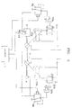
- Fig. 1 is a view showing an oil-hydraulic circuit of a flow rate control apparatus according to a preferred embodiment of the present invention
- Fig. 2 is a detailed circuit diagram of a regulator shown in Fig. 1
- Fig. 3 is a schematic view showing the internal structure of a control in Fig. 1
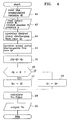
- Fig. 4 is a flowchart illustrating a control program executed by the control apparatus, a central processing unit (CPU) 25 function to control the control of the discharging control apparatus embodying the present invnetion on the basis of the control program stored in a memory 25 such as a ROM.
- CPU central processing unit
- manipulated variable input ⁇ i when an electric signal (current or voltage) according to manipulated variable input ⁇ i is input from a manipulator 11, the manipulated variable ⁇ i is entered through an analog to digital converter 29 to the CPU 25 at a step 41.
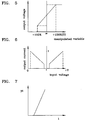
- a characteristic diagram of the manipulated variable ⁇ i and the electric signal Vi is defined such that it denotes a proportional output characterstic as shown in Fig. 5.
- a second detector 15 detects a mode M selected by an output selector 12 and the rotated number N of a motor.
- the first detectors 14a and 14b detect the discharging pressure P, that is, load pressure of variable capacity oil-hydraulic pump 3.
- the selected mode M and the rotated number N detected by the second detector and the discharging pressure detected by the first detectors are input to the CPU 25, respectively.
- the second detector 15 may be constructed such that a gear arrangement is formed to define a rotating part of the motor through a magnetic sensor so as to count the number of the gear teeth as the rotated number of the motor by way of a rotated number counter 27.
- the first detectors 14a and 14b may be one of generally well-known semiconductor sensors having the output voltage characteristic proportional to the variation of the pressure.
- the desired pump discharging rate QI can be obtained by summing the corresponding value qi toward each of manipulated variables ⁇ 1 of the manipulators.
- QI ⁇ qi.
- the actual dischargeable pump flow rate Qr is calculated by the CPU 25.
- the actually dischargeable flow rate Qr of the pump 3 can be set in a range of the maximum output in which no overload is acted on the motor 2.
- a deflection ⁇ Q is calculated between the desired pump discharging rate QI and the actual pump dischargeable pump flow rate. If the deflection ⁇ Q is below the value "0" , that is, when the desired pump discharging flow rate QI is lower than the actual pump dischargeable flow rate Qr, the desired pump discharging rate QI is set as a target pump discharging rate Q0, at a step 47. On the contrary, if the deflection ⁇ Q is equal to or lower than the value "0" , that is, when the desired pump discharging rate QI is equal to or lower than the actual pump dischargeable flow rate. Qr, this means that the overload is acted on the pump and, hence, the actual pump dischargeable flow rate Qr is set as a pump discharge flow rate Q0 to limit the output of the pump.
- the CPU 25 produces the output voltage V0 needed to assure the pump discharge flow rate Q0, the voltage is output through a digital to analog converter 32 in the controller 1 and converted into a current value I o by means of an amplifier 33 in accordance with the characteristic diagram as shown in Fig. 6 so as to drive the electromagnetic proportional pressure reducing valves 6a and 6b.
- the electromagnetic proportional pressure reducing valves 6a and 6b produce the difference of the output pilot pressure pi to the output current I o on the basis of the pilot pressure supplied from the third pump (gear pump) 4 which generates the pressurized flow serving as a control signal and then moves the inclination changed angle ⁇ in accordance with the pressure pi so that the desired pump discharging flow rate is discharged from the pump.
- the desired flow rate can be assured correctly and the maximum output of the motor can be produced in a range that no the overload is acted on the motor with result that the motor can be improved in efficiency.
- the desired pump discharging flow rate QI is calculated from the input manipulated variable ⁇ i set by an operator in consideration of the characteristic diagram of the manipulated variable and the desired pump discharging flow rate, as shown in Fig. 9 and the output characteristic diagram of the pump shown in Fig. 10.
- the pump discharging flow can be determined from the relational curve of the desired pump discharging flow rate to the manipulated value of the manipulator 11 corresponding to the variation of the load pressure on the output charateristic curve of the pump in Fig. 9 and Fig. 10 that is, the desired pump discharging flow rate can be determined in a range between the minimum value Kmin and the maximum value Kmax of the desired flow factor K to a factor HI.
- the desired flow rate factor K is operated and selected into K1 and, hence, the desired flow rate factor becomes Q3.
- the maximum pump flow allowable to the variation of the load pressure can be increased or decreased in magnitude in accordance with the selected position of the output selector 12. That is, as an output curve W1 is selected as the selected position of the output selector 12, the increase or decrease in magnitude of the desired flow rate factor becomes H1. Therefore, if the position W1 is selected under the load pressure P1, then the desired flow factor becomes K1 and the desired pump discharging flow rate is thus set to be in Q3. But, if the position W2 is selected under the same position of the manipulated value and the same pressure P1, then the factor is set to at K3 and, hence, the desired pump discharging flow rate becomes Q3'. In addition, as the load pressure is varied under the condition immediately described, the desired pump discharging flow rate may be increased or decreased depending upon the given output curve.
- the desired flow rate factor K2 is selected in a case of the same output curve W1 while the desired pump discharging flow rate becomes Q2' in a case of the same position ⁇ 1 of the manipulated value. Further, even if the composite manipulation of the manipulator 11 is executed, the desired pump discharging flow rate is operated by applying the characteristic curve of the manipulated value and the desired pump discharging flow rate as shown in Fig. 9 and the outupt characteristic curve of the pump in Fig. 10, similarily to the operation of the desired pump discharge flow rate in a single manipulation of the manipulator.
- a third selector is additionally provided to limit the actual pump flow rate of the pump as shown illustrated in Fig. 9 and Fig. 10.
- the maximum flow rate can be selected depending upon the kinds of working needed by the operator and the maximum flow rate can be further determined by the output selector 12.
- the pump discharging flow control apparatus can be defined such that the actual dischargeable pump flow rate Qmax is determined on the basis of the value selected from the characteristic diagram shown in Fig. 9, Fig. 10, and the desired pump discharging flow rate is operated from the pump discharging pressure detected by the first detector with the desired flow factor K.
- the desired pump flow is optimumly produced depending upon the manipulated variable of the manipulator, the load pressure and the variation in a position of the output diagram selected by the output selector 12 and the operated result is output as the pump discharging flow to thereby assure an operation capability needed by an operator.
- a given working can be directly and easily executed with a high resolution under a high load pressure. That is, the present invention can achieve the follwing effects.
- the operation capability of the apparatus can be improved.
- the discharing flow of the oil-hydraulic pump can be controlled in a full munipulating range of 100% so that a fine manipulation is easily achieved when operated under the high load area.
- the output can be previously controlled in accordance with the kinds of the working or the level of the load to thereby prevent energy from being lost undesirably and to retain persistence of the machine.
Landscapes
- Engineering & Computer Science (AREA)
- General Engineering & Computer Science (AREA)
- Mining & Mineral Resources (AREA)
- Structural Engineering (AREA)
- Civil Engineering (AREA)
- Mechanical Engineering (AREA)
- Physics & Mathematics (AREA)
- Fluid Mechanics (AREA)
- Chemical & Material Sciences (AREA)
- Combustion & Propulsion (AREA)
- Fluid-Pressure Circuits (AREA)
- Operation Control Of Excavators (AREA)
- Control Of Positive-Displacement Pumps (AREA)
Description
- The invention relates to a flow control apparatus for an oil-hydraulic pump, having at least one capacity variable oil-hydraulic pump driven by rotating force of a motor, a plurality of hydraulic actuators driven according to the flow rate discharged from the oil-hydraulic pump, flow control valves for adjusting the flowing direction and amount of a working oil transferred from the oil-hydraulic pump to the actuators and a control means for converting the manipulated variable into electric signal (voltage or current), an output selector means having an electric control device limiting the output power level of a motor and controlling an inclination changed angle (Q) of an inclined plate in the variable capacity oil-hydraulic pump to adjust the discharging flow rate of the pump, electromagnetic proportional pressure reducing valves for receiving a pressurized fluid from a third pump generating a constant fluid pressure on the basis of a control signal, and generating a pilot pressure depending upon the input electric signal to control the regulator, a first discharging pressure detector means for detecting the discharging pressure of the variable capacity oil-hydraulic pump and a controller for controlling the input and output signals of each of the circuit components.
- Such an apparatus is known from EP-A-376 295. The pump discharging flow rate is operated from oil-hydraulic pump, hydraulic actuators, flow control valves and control means and a target pressure is generated by detecting whether or not special joint is manipulated from one variable displacement type hydraulic pump, actuators and directional valves. The manner for controlling pump discharging flow rate on the basis of the pressure difference between the highest load pressure worked in joint and pump delivery pressure is applied.
- Accordingly, a principle object of the present invention is to provide a flow rate control apparatus for an oil-hydraulic pump, which compares a desired flow rate proportional to the manipulated variable previously set by an operator and a maximum dischargeable flow rate of an oil-hydraulic pump according to the maximumly limited output of a motor, and easily operates the desired discharge flow by means of a controller, embodying a regulator having a simple construction and improving the manipulation ability of the oil-hydraulic pump.
- Another object of the present invention is to provide a flow control apparatus for an oil-hydraulic pump, which detects the output power of the pump and reversely operates the maximum dischargable flow of the pump to extremely increase the output power of the pump under a limited output of a motor, improving energy efficiency and manipulation performance.
- Further object of the present invention is to provide a flow control apparatus for an oil-hydraulic pump wherein a characteristic curve of the pump required to a given working can be embodied by means of a controller instead of a mechnically embodying technique, preventing energy of the pump from being undesirably lost.
- Still another object of the present invention is to provide a flow control apparatus for an oil-hydraulic pump, which can control the flow rate discharged from the pump proportional to the maximum manipulated angle set by an operator under a higher load region of the pump, improving the manipulation capability of the pump smoothly and finely.
- To achieve the above object, the inventive apparatus comprises second operation means for operating a maximum dischargeable flow rate of pump from the pump pressure value obtained by the output selector means and the first discharging pressure detector means;
- a comparator for comparing the desired input flow rate with the maximum dischargeable flow rate;
- second selector means for selecting the maximum dischargeable flow rate as the output flow rate value of the pump when the desired input flow rate is larger than the maximum dischargeable flow rate; and
- a flow rate controller for controlling the dischargeable flow rate of the pump by outputting the output flow rate value of the pump to the electromagnetic proportional pressure reducing valves.
- According to the present invention thus constructed, when the manipulating means is driven to execute a given work required by an operator, flow rate required for the operation of each of the actuators is operated in accordance with the manipulated variable signal. Thus operated flow rate is subjected to calculate the opening magnitude of the flow control valve.
- Consequently, the desired pump input flow is produced by summing the desired flow rate, and the maximum dischargeable flow related to the load condition can be produced from the discharging pressure detected by the first detector means on the basis of the output power diagram previously set through the output selector means.
- The desired pump input flow rate thus produced is compared with the maximum dischargeable flow by means of a comparator means. As the comparison result, if the desired pump input flow is larger than the maximum dischargeable flow, then the maximum dischargable flow is set as the pump output value. Alternatively, if the desired pump input flow is equal to ur lower than the maximum dischargeable flow, then the desired pump input flow is output as the pump output value.
- Consequently, the pump output value is converted into electric signal by way of the output means to control the electromagnetic pressure reducing valve and the pilot pressure corresponding to the electrically converted output value is produced to drive the regulator so that the inclination changed angle of the inclined plate is moved to a predetermined position so as to discharge the desired flow rate.
- Accordingly, the output of the motor can be maximally utilized so that the output of the oil-hydraulic pump is increased to discharge the desired flow rate to thereby reduce the flow loss effectively.
- To select the output of the motor, a second detector means is provided to detect the actual rotating number of the motor. The first detector means detects the pressure of the pump so as to calculate the dischargeable pump flow rate.
- That is, the output of the rotor may be decreased in working on an upland or due to a mechanical deflection under a condition of the same rotating number of the motor. At this time, if the load is acted on the rotor, then the rotating number of the motor is to be below a referential rotating number. Accordingly, the discharging flow rate is corrected to adjust the dischargeable pump flow, so that the flow rate discharged from the pump is reduced under the same load condition.
- Furthermore, a plurality of the third detector means are provided to detect the driving speed of the actuators without the operation of the dischargable pump flow rate achieved by using the first detector means. Accordingly, the third dtectors detect the driving speed of the actuators to enable the dischargable pump flow rate to be calculated from the flow rate supplied to the actuators. Then, the rotating number of the motor is detected by the second detector means to compensate the deflection in the flow rate produced due to the variation of the load, thereby calculating the maximum dischargeable flow rate of the oil-hydraulic pump.
- In the operation of the desired pump input flow, a fuel stroke in the manupulating means is always controlled by an operator on the basis of the desired flow level of the manipulator means developed depending upon the magnitude of the load, thereby achieving the operation of the desired flow rate.
- The above and other objects, features and advantages of the invention will be apparent from the following description taken with reference to the accompanying drawings.
-
- Fig. 1
- is a view showing an oil-hydraulic circuit of a flow rate control apparatus according to a preferred embodiment of the present invention ;
- Fig. 2
- is a detailed circuit diagram of a regulator shown in Fig. 1 ;
- Fig. 3
- is a schematic view showing the internal structure of a controller in Fig. 1 ;
- Fig. 4
- is a flowchart illustrating a control program executed by the control apparatus ;
- Fig. 5
- is a graph showing a characteristic of the output voltage to the manipulated variable of a manipulator means according to the present invnetion ;
- Fig. 6
- is a graph showing a characteristic between the input current and output voltage of a dc amplifier in Fig. 1 ;
- Fig. 7
- is a graph showing an input and output characteristic of the electromagnetic pressure reducing valve shown in Fig. 1 ;
- Fig. 8
- is a graph illustrating a negative characteristic of a pump regulator ; and,
- Figs. 9 and 10
- are diagrams showing a characteristic of the pump output to the desired pump discharing flow rate of the manipulator means.
- Now, a preferred embodiment of the present invention will be described in detail.
- Referring to Figs. 1 to 4 wherein Fig. 1 is a view showing an oil-hydraulic circuit of a flow rate control apparatus according to a preferred embodiment of the present invention, Fig. 2 is a detailed circuit diagram of a regulator shown in Fig. 1, Fig. 3 is a schematic view showing the internal structure of a control in Fig. 1, and Fig. 4 is a flowchart illustrating a control program executed by the control apparatus, a central processing unit (CPU) 25 function to control the control of the discharging control apparatus embodying the present invnetion on the basis of the control program stored in a
memory 25 such as a ROM. - More specifically, when an electric signal (current or voltage) according to manipulated variable input Øi is input from a
manipulator 11, the manipulated variable Øi is entered through an analog todigital converter 29 to theCPU 25 at astep 41. A characteristic diagram of the manipulated variable Øi and the electric signal Vi is defined such that it denotes a proportional output characterstic as shown in Fig. 5. - At a
step 42, asecond detector 15 detects a mode M selected by anoutput selector 12 and the rotated number N of a motor. - The
first detectors hydraulic pump 3. The selected mode M and the rotated number N detected by the second detector and the discharging pressure detected by the first detectors are input to theCPU 25, respectively. Thesecond detector 15 may be constructed such that a gear arrangement is formed to define a rotating part of the motor through a magnetic sensor so as to count the number of the gear teeth as the rotated number of the motor by way of arotated number counter 27. Thefirst detectors - After the pressure signal is input to the
CPU 25 through an analog todigital converter 28, theCPU 25 produces a desired pump discharging flow rate corresponding to the manipulated variable Øi previously read at thestep 41. The value Q1 can be determined according to the manipulated variable Øi by using an eqution (or data) of QI=f (Øi), that is, the specified value previously set as the value shown in Fig. 9. - When
several manipulators 11 are arranged, they may be defined to designate different characteristics, respectively. In this case, the desired pump discharging rate QI can be obtained by summing the corresponding value qi toward each of manipulated variables Ø1 of the manipulators. QI = Σqi. - At a
step 44, the actual dischargeable pump flow rate Qr is calculated by theCPU 25. At thisstep 44, the characteristic diagram of themotor 2 is defined in accordance with the output mode in which the maximum output of themotor 2 is limited. Then, the output power of the pump assured through the pressure P can be produced by the following equation under the characteristic curve of the motor 2 : That is,
motor 2. - Accordingly, the actually dischargeable flow rate Qr of the
pump 3 can be set in a range of the maximum output in which no overload is acted on themotor 2. - Sequentially, at a
step 45, a deflection ΔQ is calculated between the desired pump discharging rate QI and the actual pump dischargeable pump flow rate. If the deflection ΔQ is below the value "0" , that is, when the desired pump discharging flow rate QI is lower than the actual pump dischargeable flow rate Qr, the desired pump discharging rate QI is set as a target pump discharging rate Q0, at astep 47. On the contrary, if the deflection ΔQ is equal to or lower than the value "0" , that is, when the desired pump discharging rate QI is equal to or lower than the actual pump dischargeable flow rate. Qr, this means that the overload is acted on the pump and, hence, the actual pump dischargeable flow rate Qr is set as a pump discharge flow rate Q0 to limit the output of the pump. - Consequently, if at a
step 49 theCPU 25 produces the output voltage V0 needed to assure the pump discharge flow rate Q0, the voltage is output through a digital toanalog converter 32 in thecontroller 1 and converted into a current value Io by means of anamplifier 33 in accordance with the characteristic diagram as shown in Fig. 6 so as to drive the electromagnetic proportionalpressure reducing valves - The electromagnetic proportional
pressure reducing valves - As described above, according to the present invention, the desired flow rate can be assured correctly and the maximum output of the motor can be produced in a range that no the overload is acted on the motor with result that the motor can be improved in efficiency.
- Meanwhile, in the operation of the desired pump discharging flow rate QI at the
step 43, the desired pump discharging flow rate QI is calculated from the input manipulated variable Øi set by an operator in consideration of the characteristic diagram of the manipulated variable and the desired pump discharging flow rate, as shown in Fig. 9 and the output characteristic diagram of the pump shown in Fig. 10. Next, the discharging pressure P from the first detector which detects the discharging pressure of the oil-hydraulic pump 3 and the desired flow rate factor K can be increased or decreased by the following relation established between the manipulated pressure and the desired pump discharging flow rate QI on the basis of the detected pressure. That is :
- As previously noted, the desired flow rate factor is fixedly set to the specified inclination (i.e., K = K max) regardless the desirably manipulated value of the
manipulator 11 to be 100% or Øi unless the pressure is varied under the pump discharging pressure P. Accordingly, if the manipulated value is above Øi, the desired pump discharging flow rate is fixed at QI = Q1. - According to the present invention, but, the pump discharging flow can be determined from the relational curve of the desired pump discharging flow rate to the manipulated value of the
manipulator 11 corresponding to the variation of the load pressure on the output charateristic curve of the pump in Fig. 9 and Fig. 10 that is, the desired pump discharging flow rate can be determined in a range between the minimum value Kmin and the maximum value Kmax of the desired flow factor K to a factor HI. - In other words, when the manipulated value of the
manipulator 11 is Øi and the pump load pressure is P1, then the desired flow rate factor K is operated and selected into K1 and, hence, the desired flow rate factor becomes Q3. - Moreover, the maximum pump flow allowable to the variation of the load pressure can be increased or decreased in magnitude in accordance with the selected position of the
output selector 12. That is, as an output curve W1 is selected as the selected position of theoutput selector 12, the increase or decrease in magnitude of the desired flow rate factor becomes H1. Therefore, if the position W1 is selected under the load pressure P1, then the desired flow factor becomes K1 and the desired pump discharging flow rate is thus set to be in Q3. But, if the position W2 is selected under the same position of the manipulated value and the same pressure P1, then the factor is set to at K3 and, hence, the desired pump discharging flow rate becomes Q3'. In addition, as the load pressure is varied under the condition immediately described, the desired pump discharging flow rate may be increased or decreased depending upon the given output curve. - More specifically, when the pump load pressure is decreased from P1 to P2, the desired flow rate factor K2 is selected in a case of the same output curve W1 while the desired pump discharging flow rate becomes Q2' in a case of the same position Ø1 of the manipulated value. Further, even if the composite manipulation of the
manipulator 11 is executed, the desired pump discharging flow rate is operated by applying the characteristic curve of the manipulated value and the desired pump discharging flow rate as shown in Fig. 9 and the outupt characteristic curve of the pump in Fig. 10, similarily to the operation of the desired pump discharge flow rate in a single manipulation of the manipulator. - More specifically, assuming that two
actuators 9 and 16 are provided for the single oil-hydraulic pump, when the manipulated variable of the first manipulator is Ø1 and that of the second manipulator is Ø2 under the output diagram W1 of theoutput selector 12 and the pump load pressure P1, the desired flow factor becomes K1, and the first desired pump discharging flow rate Q3 and the second desired pump discharging flow rate Q4 can be produced using the factor K1. When the sum of the first and second desired flow Q3 and Q4 is Qt and the actual pump dischargeable flow rate in the factor K1 is Q1max, if the total of the desired pump flow is equal to or lower than the actual pump dischargeable flow rate (i.e., Qt≥Q1 max) as the comparison of the sum Qt and the actual pump dischargeable flow rate Q1max, then the total desired pump discharging flow rate is taken as the desired pump flow (that is, QI = Qt). - Alternatively, if the total of the desired pump flow Qt is larger than the actual pump dischargeable flow rate Q1max that is, Qt (Q1max, the maximum dischargeable flow is selected as the desired pump discharging flow rate (i.e., QI = Q1max).
- Furthermore, a third selector is additionally provided to limit the actual pump flow rate of the pump as shown illustrated in Fig. 9 and Fig. 10. With the use of the third selector, the maximum flow rate can be selected depending upon the kinds of working needed by the operator and the maximum flow rate can be further determined by the
output selector 12. - Accordingly, the pump discharging flow control apparatus can be defined such that the actual dischargeable pump flow rate Qmax is determined on the basis of the value selected from the characteristic diagram shown in Fig. 9, Fig. 10, and the desired pump discharging flow rate is operated from the pump discharging pressure detected by the first detector with the desired flow factor K.
- While the desired pump discharging flow rate and the output diagram WI are illustrated in a form of straight line and curve, respectively, it should be noticed that the present invention is not limited to the specified form. Accordingly, the diagram will be changed in various formats according to the characteristic of the hydraulic machine or format needed by an operator and subjected to the formulation or datamation.
- According to the present invention, the desired pump flow is optimumly produced depending upon the manipulated variable of the manipulator, the load pressure and the variation in a position of the output diagram selected by the
output selector 12 and the operated result is output as the pump discharging flow to thereby assure an operation capability needed by an operator. As a result, a given working can be directly and easily executed with a high resolution under a high load pressure. That is, the present invention can achieve the follwing effects. - Firstly, the operation capability of the apparatus can be improved. The discharing flow of the oil-hydraulic pump can be controlled in a full munipulating range of 100% so that a fine manipulation is easily achieved when operated under the high load area.
- Secondly, the output can be previously controlled in accordance with the kinds of the working or the level of the load to thereby prevent energy from being lost undesirably and to retain persistence of the machine.
- In a conventional negative control or full power control employed to control the discharging flow of the existing oil-hydraulic pump, several control singnal input ports for the pump regulator are provided thereto, so the construction is complicated and control accuracy is thus deteriorated. But, according to the present invention, only single input port is provided for control of the regulator. Accordingly, the system can be easily constructed with the improved control accuracy.
Claims (5)
- A flow control apparatus for an oil-hydraulic pump (3), having at least one capacity variable oil-hydraulic pump driven by rotating force of a motor (2, 15), a plurality of hydraulic actuators (10, 18) driven according to the flow rate discharged from the oil-hydraulic pump, flow control valves (8a, 8b) for adjusting the flowing direction and amount of a working oil transferred from the oil-hydraulic pump (3) to the actuators (10, 18) and a control means for converting the manipulated variable into electric signal (voltage or current), an output selector means (12) having an electric control device limiting the output power level of a motor and controlling an inclination changed angle (Q) of an inclined plate in the variable capacity oil-hydraulic pump (3) to adjust the discharging flow rate of the pump, electromagnetic proportional pressure reducing valves (6a, 6b) for receiving a pressurized fluid from a third pump (4) generating a constant fluid pressure on the basis of a control signal, and generating a pilot pressure depending upon the input electric signal to control the regulator, a first discharging pressure detector means (14a, 14b) for detecting the discharging pressure of the variable capacity oil-hydraulic pump (3) and a controller for controlling the input and output signals of each of the circuit components, the apparatus comprising:second operation means for operating a maximum dischargeable flow rate of pump from the pump pressure value obtained by the output selector means (12) and the first discharging pressure detector means (14a, 14b);a comparator for comparing the desired input flow rate with the maximum dischargeable flow rate;second selector means for selecting the maximum dischargeable flow rate as the output flow rate value of the pump (3) when the desired input flow rate is larger than the maximum dischargeable flow rate; anda flow rate controller for controlling the dischargeable flow rate of the pump (3) by outputting the output flow rate value of the pump to the electromagnetic proportional pressure reducting valves (7a, 7b).
- A flow rate control apparatus for an oil-hydraulic pump according to claim 1, wherein the first operation means selects the desired flow rate factor (that is, characteristic diagram of the manipulated variable of the manipulator means and the desired flow rate) in accordance with the pump load pressure detected by the first detector menas (14a, 14b) and the output diagram selected by the output selector means (12), and then operates the desired pump discharging flow rate according to the manipulated variable of the manipulator on the basis of the desired flow factor.
- A flow rate control apparatus for an oil-hydraulic pump according to claim 1, further comprising a second detector means (9) for detecting the actually rotated number (N) of the motor, wherein the second operation means produces the deflection ΔQ between the target rotating number and the actually rotated number of the motor, operates the compensation flow by using the power value selected by the output selector means (12) and the pump pressure value supplied from the pressure cursor and then produces the maximum dischargeable flow rate of the pump (3).
- A flow rate control apparatus for an oil-hydraulic pump according to claim 2, further comprising a plurality of third detections means for detecting the driving speed (or position) of the actuators (10, 18), and the second operation means operates the driving flow of each of the actuators (10, 18) from the driving speed detected by the third detectors, calculates the total discharging flow rate of the pump on the basis of the driving flow, receives the deflection between the target rotating number and the actually rotated number of the motor from the second detectors means and operates the compensation flow rate on the basis of the power value selected by the output selector means (12), and operates the actual dischargeable flow rate of the oil-hydraulic pump (3) in accordance with the compensation flow rate.
- A flow rate control apparatus for an oil-hydraulic pump according to claim 1, further comprising single third detector means for selecting the level of the maximum dischargeable pump flow rate, and the characteristic diagram (i.e., the desired flow factor) of the manipulated variable of the manipulator means and the desired pump flow is operated in accordance with the level of the actual dischargeable flow rate selected by the third selector means, and the desired pump flow corresponding the manipulated variable is operated on the basis of the desired flow factor.
Applications Claiming Priority (2)
| Application Number | Priority Date | Filing Date | Title |
|---|---|---|---|
| KR1019910021924A KR950008533B1 (en) | 1991-11-30 | 1991-11-30 | Control devices output of hydraulic pump |
| KR9121924 | 1991-11-30 |
Publications (2)
| Publication Number | Publication Date |
|---|---|
| EP0545271A1 EP0545271A1 (en) | 1993-06-09 |
| EP0545271B1 true EP0545271B1 (en) | 1997-10-01 |
Family
ID=19323983
Family Applications (1)
| Application Number | Title | Priority Date | Filing Date |
|---|---|---|---|
| EP92120144A Expired - Lifetime EP0545271B1 (en) | 1991-11-30 | 1992-11-26 | Flow rate control apparatus for oil-hydraulic pump |
Country Status (4)
| Country | Link |
|---|---|
| US (1) | US5303551A (en) |
| EP (1) | EP0545271B1 (en) |
| KR (1) | KR950008533B1 (en) |
| DE (1) | DE69222508T2 (en) |
Families Citing this family (35)
| Publication number | Priority date | Publication date | Assignee | Title |
|---|---|---|---|---|
| DE4308198C1 (en) * | 1993-03-15 | 1994-07-28 | Rexroth Mannesmann Gmbh | Torque control via swivel angle or eccentricity in hydrostatic machines with axial and radial piston arrangement |
| KR0171389B1 (en) * | 1993-07-02 | 1999-03-30 | 토니헬샴 | Control device and method for hydraulic construction machinery |
| KR950019129A (en) * | 1993-12-30 | 1995-07-22 | 김무 | Engine-pump control device and method of hydraulic construction machine |
| US5540049A (en) * | 1995-08-01 | 1996-07-30 | Caterpillar Inc. | Control system and method for a hydraulic actuator with velocity and force modulation control |
| JP3567051B2 (en) * | 1996-06-12 | 2004-09-15 | 新キャタピラー三菱株式会社 | Operation control device for hydraulic actuator |
| US5875630A (en) * | 1997-06-10 | 1999-03-02 | Sauer Inc. | Hydraulic drive assembly |
| JP3383754B2 (en) * | 1997-09-29 | 2003-03-04 | 日立建機株式会社 | Hydraulic construction machine hydraulic pump torque control device |
| JP3419661B2 (en) * | 1997-10-02 | 2003-06-23 | 日立建機株式会社 | Auto accelerator device for prime mover of hydraulic construction machinery and control device for prime mover and hydraulic pump |
| DE19824319A1 (en) * | 1998-06-02 | 1999-12-16 | O & K Mining Gmbh | Method for regulating in particular the swiveling device of a mobile machine |
| US6305419B1 (en) | 2000-07-14 | 2001-10-23 | Clark Equipment Company | Variable pilot pressure control for pilot valves |
| US6591697B2 (en) * | 2001-04-11 | 2003-07-15 | Oakley Henyan | Method for determining pump flow rates using motor torque measurements |
| US7726948B2 (en) * | 2002-04-03 | 2010-06-01 | Slw Automotive Inc. | Hydraulic pump with variable flow and variable pressure and electric control |
| DE60333503D1 (en) * | 2002-04-03 | 2010-09-02 | Slw Automotive Inc | Pump with variable capacity and control for it |
| DE10307190A1 (en) * | 2003-02-20 | 2004-09-16 | O & K Orenstein & Koppel Gmbh | Method for controlling a hydraulic system of a mobile work machine |
| US7165397B2 (en) | 2003-11-10 | 2007-01-23 | Timberjack, Inc. | Anti-stall pilot pressure control system for open center systems |
| US20090090102A1 (en) * | 2006-05-03 | 2009-04-09 | Wilfred Busse | Method of reducing the load of one or more engines in a large hydraulic excavator |
| JP5330945B2 (en) * | 2008-10-29 | 2013-10-30 | 三菱重工業株式会社 | Hydraulic system and wind power generator equipped with the same |
| KR101582689B1 (en) * | 2009-06-02 | 2016-01-05 | 두산인프라코어 주식회사 | Swing control apparatus and swing control method for construction machinery |
| US20110056194A1 (en) * | 2009-09-10 | 2011-03-10 | Bucyrus International, Inc. | Hydraulic system for heavy equipment |
| US20110056192A1 (en) * | 2009-09-10 | 2011-03-10 | Robert Weber | Technique for controlling pumps in a hydraulic system |
| KR101514465B1 (en) * | 2009-11-18 | 2015-04-23 | 두산인프라코어 주식회사 | Hydraulic pump control apparatus for construction machinery and hydraulic pump control method for the same |
| US8606451B2 (en) | 2010-10-06 | 2013-12-10 | Caterpillar Global Mining Llc | Energy system for heavy equipment |
| US8718845B2 (en) | 2010-10-06 | 2014-05-06 | Caterpillar Global Mining Llc | Energy management system for heavy equipment |
| US8626403B2 (en) | 2010-10-06 | 2014-01-07 | Caterpillar Global Mining Llc | Energy management and storage system |
| KR101754423B1 (en) * | 2010-12-22 | 2017-07-20 | 두산인프라코어 주식회사 | Hydraulic pump controlling method for an excavator |
| KR101847882B1 (en) * | 2010-12-28 | 2018-04-11 | 볼보 컨스트럭션 이큅먼트 에이비 | Method of controlling the flow rate of a variable capacity hydraulic pump for a construction apparatus |
| US9190852B2 (en) | 2012-09-21 | 2015-11-17 | Caterpillar Global Mining Llc | Systems and methods for stabilizing power rate of change within generator based applications |
| CA2915498A1 (en) * | 2013-06-26 | 2014-12-31 | Volvo Construction Equipment Ab | Device for controlling control valve of construction machine, method for controlling same, and method for controlling discharge flow rate of hydraulic pump |
| CN105358769B (en) * | 2014-06-04 | 2017-10-03 | 株式会社小松制作所 | The posture operation method of the posture arithmetic unit of Work machine, Work machine and Work machine |
| JP6430735B2 (en) * | 2014-07-09 | 2018-11-28 | 日立建機株式会社 | Drive device for work machine |
| FR3035829B1 (en) * | 2015-05-05 | 2018-09-14 | Poclain Hydraulics Industrie | HYDRAULIC ASSISTING SYSTEM FOR MOTORIZED ENGINE WITH OPEN CIRCUIT |
| JP6982158B2 (en) * | 2017-02-17 | 2021-12-17 | ヤンマーパワーテクノロジー株式会社 | Hydraulic machine control device |
| EP3724409A4 (en) * | 2017-12-14 | 2022-01-12 | Volvo Construction Equipment AB | Hydraulic machine |
| US11454003B2 (en) | 2018-09-10 | 2022-09-27 | Artemis Intelligent Power Limited | Apparatus with hydraulic machine controller |
| IT201900015674A1 (en) * | 2019-09-05 | 2021-03-05 | Calpeda A Spa | Method of protection and management of actuation of a pressurization system |
Family Cites Families (14)
| Publication number | Priority date | Publication date | Assignee | Title |
|---|---|---|---|---|
| DE3049938A1 (en) * | 1979-10-15 | 1982-03-18 | Y Aoyagi | Method of controlling internal combustion engine and hydraulic pump system |
| US4579021A (en) * | 1982-04-30 | 1986-04-01 | Nissan Motor Co., Ltd. | Method and apparatus for controlling line pressure in continuously variable transmission |
| DE3319408A1 (en) * | 1983-05-28 | 1984-11-29 | Robert Bosch Gmbh, 7000 Stuttgart | POWER STEERING DEVICE WITH AT LEAST ONE HYDRAULIC ADDITIONAL CONSUMER CONNECTED TO IT |
| JPS6084464A (en) * | 1983-10-14 | 1985-05-13 | Nissan Motor Co Ltd | Hydraulic control unit for automatic transmission |
| US4742676A (en) * | 1984-12-24 | 1988-05-10 | Linde Aktiengesellschaft | Reversible hydrostatic transmission pump with drive engine speed control |
| US4741159A (en) * | 1986-04-08 | 1988-05-03 | Vickers, Incorporated | Power transmission |
| JPH0535249Y2 (en) * | 1988-03-31 | 1993-09-07 | ||
| US5048293A (en) * | 1988-12-29 | 1991-09-17 | Hitachi Construction Machinery Co., Ltd. | Pump controlling apparatus for construction machine |
| EP0432266B2 (en) * | 1989-01-18 | 1997-08-13 | Hitachi Construction Machinery Co., Ltd. | Hydraulic driving unit for construction machinery |
| JPH02221702A (en) * | 1989-02-22 | 1990-09-04 | Nireco Corp | Electric hydraulic servomotor |
| US4936340A (en) * | 1989-06-21 | 1990-06-26 | Coretest Systems, Inc. | Pressure regulator |
| US5174114A (en) * | 1990-02-28 | 1992-12-29 | Hitachi Construction Machinery Co., Ltd. | Hydraulic drive system for construction machine |
| US5111660A (en) * | 1991-03-11 | 1992-05-12 | Ford Motor Company | Parallel flow electronically variable orifice for variable assist power steering system |
| US5167121A (en) * | 1991-06-25 | 1992-12-01 | University Of British Columbia | Proportional hydraulic control |
-
1991
- 1991-11-30 KR KR1019910021924A patent/KR950008533B1/en not_active IP Right Cessation
-
1992
- 1992-11-25 US US07/981,218 patent/US5303551A/en not_active Expired - Lifetime
- 1992-11-26 EP EP92120144A patent/EP0545271B1/en not_active Expired - Lifetime
- 1992-11-26 DE DE69222508T patent/DE69222508T2/en not_active Expired - Lifetime
Also Published As
| Publication number | Publication date |
|---|---|
| DE69222508D1 (en) | 1997-11-06 |
| US5303551A (en) | 1994-04-19 |
| KR930010392A (en) | 1993-06-22 |
| EP0545271A1 (en) | 1993-06-09 |
| KR950008533B1 (en) | 1995-07-31 |
| DE69222508T2 (en) | 1998-05-07 |
Similar Documents
| Publication | Publication Date | Title |
|---|---|---|
| EP0545271B1 (en) | Flow rate control apparatus for oil-hydraulic pump | |
| EP0376295B1 (en) | Hydraulic drive controlling apparatus for construction machine | |
| EP1798346B1 (en) | Control device for hydraulic drive machine | |
| EP0644335A1 (en) | Hydraulic drive for hydraulic work machine | |
| US4507057A (en) | Control system for hydraulic pumps of a civil machine | |
| US7272928B2 (en) | Hydraulic circuit of construction machinery | |
| US5214916A (en) | Control system for a hydraulic work vehicle | |
| US5295795A (en) | Hydraulic drive system for construction machine | |
| EP0632355B1 (en) | Discharge flow control system and method in hydraulic pump | |
| JPH0359227A (en) | Pump discharge quantity control system for construction machine | |
| EP2660477B1 (en) | Method of controlling the flow rate of a variable capacity hydraulic pump for a construction apparatus | |
| EP0796952A1 (en) | Control system for construction machine | |
| EP2918735B1 (en) | Hydraulic driving apparatus for working machine | |
| JPH07101041B2 (en) | Proportional valve controller for fluid system | |
| JPH07208404A (en) | Equipment and method of controlling engine and pump of hydraulic type construction equipment | |
| JP2567193B2 (en) | Hydraulic pump discharge flow control device | |
| EP0922813A2 (en) | hydraulic drive system for hydraulic work vehicle | |
| US5434785A (en) | System for automatically controlling quantity of hydraulic fluid of an excavator | |
| US6651428B2 (en) | Hydraulic drive device | |
| EP0539589A1 (en) | Method and unit for controlling vehicle for loading operation | |
| EP0572678A1 (en) | Hydraulic driving apparatus for construction machines | |
| US6772590B2 (en) | Hydraulic driving device | |
| KR960004630B1 (en) | Control devices of hydraulic machines | |
| JP3099538B2 (en) | Switching control device for directional control valve | |
| JPH0641762B2 (en) | Drive control device for hydraulic circuit |
Legal Events
| Date | Code | Title | Description |
|---|---|---|---|
| PUAI | Public reference made under article 153(3) epc to a published international application that has entered the european phase |
Free format text: ORIGINAL CODE: 0009012 |
|
| AK | Designated contracting states |
Kind code of ref document: A1 Designated state(s): DE FR GB IT |
|
| 17P | Request for examination filed |
Effective date: 19931126 |
|
| 17Q | First examination report despatched |
Effective date: 19950314 |
|
| GRAG | Despatch of communication of intention to grant |
Free format text: ORIGINAL CODE: EPIDOS AGRA |
|
| GRAH | Despatch of communication of intention to grant a patent |
Free format text: ORIGINAL CODE: EPIDOS IGRA |
|
| GRAH | Despatch of communication of intention to grant a patent |
Free format text: ORIGINAL CODE: EPIDOS IGRA |
|
| GRAA | (expected) grant |
Free format text: ORIGINAL CODE: 0009210 |
|
| RAP1 | Party data changed (applicant data changed or rights of an application transferred) |
Owner name: SAMSUNG HEAVY INDUSTRIES CO., LTD |
|
| AK | Designated contracting states |
Kind code of ref document: B1 Designated state(s): DE FR GB IT |
|
| REF | Corresponds to: |
Ref document number: 69222508 Country of ref document: DE Date of ref document: 19971106 |
|
| ITF | It: translation for a ep patent filed |
Owner name: STUDIO JAUMANN P. & C. S.N.C. |
|
| ET | Fr: translation filed | ||
| PLBE | No opposition filed within time limit |
Free format text: ORIGINAL CODE: 0009261 |
|
| STAA | Information on the status of an ep patent application or granted ep patent |
Free format text: STATUS: NO OPPOSITION FILED WITHIN TIME LIMIT |
|
| 26N | No opposition filed | ||
| REG | Reference to a national code |
Ref country code: FR Ref legal event code: TP |
|
| REG | Reference to a national code |
Ref country code: GB Ref legal event code: 732E |
|
| REG | Reference to a national code |
Ref country code: GB Ref legal event code: IF02 |
|
| REG | Reference to a national code |
Ref country code: GB Ref legal event code: 732E |
|
| PGFP | Annual fee paid to national office [announced via postgrant information from national office to epo] |
Ref country code: DE Payment date: 20091119 Year of fee payment: 18 |
|
| PGFP | Annual fee paid to national office [announced via postgrant information from national office to epo] |
Ref country code: IT Payment date: 20091119 Year of fee payment: 18 Ref country code: FR Payment date: 20091123 Year of fee payment: 18 Ref country code: GB Payment date: 20091125 Year of fee payment: 18 |
|
| GBPC | Gb: european patent ceased through non-payment of renewal fee |
Effective date: 20101126 |
|
| REG | Reference to a national code |
Ref country code: DE Ref legal event code: R119 Ref document number: 69222508 Country of ref document: DE Effective date: 20110601 Ref country code: DE Ref legal event code: R119 Ref document number: 69222508 Country of ref document: DE Effective date: 20110531 |
|
| REG | Reference to a national code |
Ref country code: FR Ref legal event code: ST Effective date: 20110801 |
|
| PG25 | Lapsed in a contracting state [announced via postgrant information from national office to epo] |
Ref country code: DE Free format text: LAPSE BECAUSE OF NON-PAYMENT OF DUE FEES Effective date: 20110531 |
|
| PG25 | Lapsed in a contracting state [announced via postgrant information from national office to epo] |
Ref country code: FR Free format text: LAPSE BECAUSE OF NON-PAYMENT OF DUE FEES Effective date: 20101130 |
|
| PG25 | Lapsed in a contracting state [announced via postgrant information from national office to epo] |
Ref country code: GB Free format text: LAPSE BECAUSE OF NON-PAYMENT OF DUE FEES Effective date: 20101126 |
|
| PG25 | Lapsed in a contracting state [announced via postgrant information from national office to epo] |
Ref country code: IT Free format text: LAPSE BECAUSE OF NON-PAYMENT OF DUE FEES Effective date: 20101126 |