EP0545142A1 - Router - Google Patents
Router Download PDFInfo
- Publication number
- EP0545142A1 EP0545142A1 EP92119670A EP92119670A EP0545142A1 EP 0545142 A1 EP0545142 A1 EP 0545142A1 EP 92119670 A EP92119670 A EP 92119670A EP 92119670 A EP92119670 A EP 92119670A EP 0545142 A1 EP0545142 A1 EP 0545142A1
- Authority
- EP
- European Patent Office
- Prior art keywords
- guide sleeve
- milling machine
- clamping
- machine according
- hand milling
- Prior art date
- Legal status (The legal status is an assumption and is not a legal conclusion. Google has not performed a legal analysis and makes no representation as to the accuracy of the status listed.)
- Granted
Links
Images

Classifications
-
- B—PERFORMING OPERATIONS; TRANSPORTING
- B23—MACHINE TOOLS; METAL-WORKING NOT OTHERWISE PROVIDED FOR
- B23Q—DETAILS, COMPONENTS, OR ACCESSORIES FOR MACHINE TOOLS, e.g. ARRANGEMENTS FOR COPYING OR CONTROLLING; MACHINE TOOLS IN GENERAL CHARACTERISED BY THE CONSTRUCTION OF PARTICULAR DETAILS OR COMPONENTS; COMBINATIONS OR ASSOCIATIONS OF METAL-WORKING MACHINES, NOT DIRECTED TO A PARTICULAR RESULT
- B23Q35/00—Control systems or devices for copying directly from a pattern or a master model; Devices for use in copying manually
- B23Q35/04—Control systems or devices for copying directly from a pattern or a master model; Devices for use in copying manually using a feeler or the like travelling along the outline of the pattern, model or drawing; Feelers, patterns, or models therefor
- B23Q35/08—Means for transforming movement of the feeler or the like into feed movement of tool or work
- B23Q35/10—Means for transforming movement of the feeler or the like into feed movement of tool or work mechanically only
- B23Q35/101—Means for transforming movement of the feeler or the like into feed movement of tool or work mechanically only with a pattern composed of one or more lines used simultaneously for one tool
- B23Q35/102—Means for transforming movement of the feeler or the like into feed movement of tool or work mechanically only with a pattern composed of one or more lines used simultaneously for one tool of one line
- B23Q35/104—Means for transforming movement of the feeler or the like into feed movement of tool or work mechanically only with a pattern composed of one or more lines used simultaneously for one tool of one line with coaxial tool and feeler
-
- B—PERFORMING OPERATIONS; TRANSPORTING
- B27—WORKING OR PRESERVING WOOD OR SIMILAR MATERIAL; NAILING OR STAPLING MACHINES IN GENERAL
- B27C—PLANING, DRILLING, MILLING, TURNING OR UNIVERSAL MACHINES FOR WOOD OR SIMILAR MATERIAL
- B27C5/00—Machines designed for producing special profiles or shaped work, e.g. by rotary cutters; Equipment therefor
- B27C5/10—Portable hand-operated wood-milling machines; Routers
Definitions
- the invention is based on a hand milling machine according to the preamble of claim 1.
- a hand milling machine with a guide sleeve arranged around the milling tool is already known, by means of which it can be milled along a template to be placed on the workpiece.
- the guide sleeve shown there is attached to the underside of the motor housing with a connecting bolt. This makes it difficult to attach and remove the guide sleeve because of the poor accessibility of the bolt. There is also the risk that the connecting bolt is lost when the guide sleeve is not used.
- the hand milling machine according to the invention with the characterizing features of claim 1 has the advantage that the guide sleeve, which is subjected to rotation by friction on a template, can be easily and securely connected to the motor housing and dismantled again.
- the bayonet catch is designed in such a way that the guide sleeve cannot twist and cannot loosen while being guided along a template. This is achieved in particular by that the rotatable part of the bayonet lock is integrated as a clamping ring in the footplate.
- the measures listed in the dependent claims allow advantageous developments and improvements of the hand milling machine specified in claim 1. It is particularly advantageous if the clamping ring is forced into its end position fixing the guide sleeve by a spring.
- a firm hold of the guide sleeve is achieved in that it has, in particular, beveled clamping surfaces that come to rest between clamping cams on the clamping ring and stops on the footplate.
- the guide sleeve is secured against twisting by indentations and projections on the stops of the footplate.
- the clamping ring is advantageously provided with a handle for turning against the pulling direction of the spring, which protrudes laterally from the opening from the footplate.
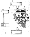
- FIG. 1 shows a longitudinal section through a hand milling machine.
- FIG. 2 shows a view of a clamping ring with a guide sleeve from viewing direction II in FIG. 3
- FIG. 3 shows a section through a plug connection and
- FIGS. 4 and 5 show a guide sleeve.
- the router 2 which is designed as a router, consists of a multi-part motor housing 3 made of aluminum and / or plastic. Two handles 4 sit on the housing 3, an electrical switch 5 being installed in one of the handles. The switch 5 is electrically connected to the power cord 6 and the drive motor 7.
- the housing 3 has vertically aligned guide tubes 9 which are guided on two guide columns 11 which also protrude vertically from a base plate 10.
- the aluminum base plate 10 is equipped with a plastic sole 12 to protect the workpiece to be machined.
- Base plate 10 and sole 12 have an opening 13 centrally into which a spindle 14 driven by motor 7 projects.
- the spindle 14 is equipped at its lower end with a tool holder, in particular an adapter sleeve 15.
- a milling tool 16 is held interchangeably therein.
- the motor housing 3 is displaceable along the columns 11 with respect to the base plate 10, so that a tool 16 inserted into the clamping sleeve 15 is more or less immersed in the workpiece to be machined.
- a plug device 17 for receiving a guide sleeve 18 is fitted in the opening 13.
- This consists of a tubular guide part 19 surrounding the tool 16 and a radially projecting collar 20 formed thereon.
- the guide part 19 is interchangeable and can have different diameters depending on the tool used.
- the collar 20 bears with its outer edge against stops 22 of the foot plate 10 which protrude into the opening 13. In the exemplary embodiment, four stops 22 are provided. Attached to these in each case is a downwardly directed projection 23 which extends in the axial direction of the opening 13 and which engages in associated notches 24 on the edge of the guide sleeve 18 in order to prevent the guide sleeve 18 from rotating relative to the base plate 10 (see also FIGS. 2 and 4) ).
- the guide sleeve 18 is held by a rotatable clamping ring 26 in fixed contact with the stops 22.
- the clamping ring 26 is inserted between the base plate 10 and the sole 12 and is held in its locking-side end position by a tension spring 27 held on the base plate, in particular suspended in a rib of the base plate crowded.
- Four clamping cams 28 protrude radially inward from the clamping ring 26, which are chamfered towards the stops 22 and hold the guide sleeve 18.
- the clamping ring 26 also has two circumferentially extending elongated holes 29 into which guide pins 30 attached to the footplate 10 engage.
- a handle 31 protrudes upwards in the axial direction through a curved slot in the footplate 10.
- the guide sleeve 18 has on its collar 20, in addition to the notches 24 for the anti-rotation device, cutouts 32 for the passage of the clamping cams 28.
- the cutouts 32 are followed by clamping surfaces 33 which are bent slightly upward from the plane of the collar 20 (see FIG. 5 ).
- the clamping surfaces 33 like the clamping cams 28, are thus inclined to the plane of rotation of the clamping ring 26.
- Stops 22, clamping ring 26 and collar 20 of the guide sleeve 18 together form a bayonet lock 34.
- the guide sleeve 18 is mounted by simply inserting the sleeve 18 into the opening 13 when unlocked, that is to say to the left in relation to the illustration in FIG. 2 by approximately 40 ° rotated clamping ring 26.
- the collar 20 with its recesses 32 is pushed over the laterally offset clamping cams 28.
- the handle 31 is released. Then the clamping ring 26 rotates back under spring force into its locking position shown in FIG.
- the bevels ensure permanently reliable fixing of the guide sleeve 18.
- the bevels are designed in this way that the clamping ring 26 does not return fully to the end position shown in FIG. 2 when the guide sleeve 18 is inserted, as can be seen from the position of the pins 30 in the elongated holes 29. This makes it one of the best when working along templates stable leadership ensured.
- the guide sleeve 18 is neither rotated when it is inserted nor later when the milling cutter 2 is in use and therefore cannot come loose automatically.
Abstract
Description
Die Erfindung geht aus von einer Handfräse nach dem Oberbegriff des Anspruchs 1. Aus der US 1 745 780 ist bereits eine Handfräse mit einer um das Fräswerkzeug herum angeordneten Führungshülse bekannt, mittels derer entlang einer auf das Werkstück aufzulegenden Schablone gefräst werden kann. Die dort gezeigte Führungshülse ist mit einem Verbindungsbolzens an der Unterseite des Motorgehäuses befestigt. Dies erschwert wegen der schlechten Zugänglichkeit des Bolzens die Befestigung und die Demontage der Führungshülse. Außerdem besteht die Gefahr, daß der Verbindungsbolzen bei nicht benutzter Führungshülse verloren geht.The invention is based on a hand milling machine according to the preamble of claim 1. From US 1 745 780 a hand milling machine with a guide sleeve arranged around the milling tool is already known, by means of which it can be milled along a template to be placed on the workpiece. The guide sleeve shown there is attached to the underside of the motor housing with a connecting bolt. This makes it difficult to attach and remove the guide sleeve because of the poor accessibility of the bolt. There is also the risk that the connecting bolt is lost when the guide sleeve is not used.
Die erfindungsgemäße Handfräse mit den kennzeichnenden Merkmalen des Anspruchs 1 hat demgegenüber den Vorteil, daß die durch Reibung an einer Schablone auf Drehung beanspruchte Führungshülse einfach und sicher mit dem Motorgehäuse verbunden und wieder demontiert werden kann. Der Bajonettverschluß ist so ausgeführt, daß sich die Führungshülse während des Entlangführens an einer Schablone nicht verdrehen und nicht lösen kann. Dies wird insbesondere dadurch erreicht, daß der drehbare Teil des Bajonettverschlusses als Spannring in die Fußplatte integriert ist.The hand milling machine according to the invention with the characterizing features of claim 1 has the advantage that the guide sleeve, which is subjected to rotation by friction on a template, can be easily and securely connected to the motor housing and dismantled again. The bayonet catch is designed in such a way that the guide sleeve cannot twist and cannot loosen while being guided along a template. This is achieved in particular by that the rotatable part of the bayonet lock is integrated as a clamping ring in the footplate.
Durch die in den abhängigen Ansprüchen aufgeführten Maßnahmen sind vorteilhafte Weiterbildungen und Verbesserungen der im Anspruch 1 angegebenen Handfräse möglich. Besonders vorteilhaft ist es, wenn der Spannring durch eine Feder in seine die Führungshülse fixierende Endstellung gedrängt wird. Ein fester Halt der Führungshülse wird dadurch erreicht, daß diese insbesondere abgeschrägte Klemmflächen aufweist, die zwischen Spannocken am Spannring und Anschlägen an der Fußplatte zu liegen kommen. Gegen Verdrehen ist die Führungshülse durch Einkerbungen und Vorsprünge an den Anschlägen der Fußplatte gesichert. Vorteilhafterweise ist der Spannring mit einer Handhabe zum Verdrehen entgegen der Zugrichtung der Feder versehen, die seitlich der Öffnung aus der Fußplatte hervorragt.The measures listed in the dependent claims allow advantageous developments and improvements of the hand milling machine specified in claim 1. It is particularly advantageous if the clamping ring is forced into its end position fixing the guide sleeve by a spring. A firm hold of the guide sleeve is achieved in that it has, in particular, beveled clamping surfaces that come to rest between clamping cams on the clamping ring and stops on the footplate. The guide sleeve is secured against twisting by indentations and projections on the stops of the footplate. The clamping ring is advantageously provided with a handle for turning against the pulling direction of the spring, which protrudes laterally from the opening from the footplate.
Ein Ausführungsbeispiel der Erfindung dargestellt und in der nachfolgenden Beschreibung näher erläutert. Figur 1 zeigt einen Längsschnitt durch eine Handfräse. Figur 2 zeigt eine Ansicht eines Spannrings mit Führungshülse aus Blickrichtung II in Figur 3, Figur 3 zeigt einen Schnitt durch eine Steckverbindung und die Figuren 4 und 5 zeigen eine Führungshülse.An embodiment of the invention is shown and explained in more detail in the following description. Figure 1 shows a longitudinal section through a hand milling machine. FIG. 2 shows a view of a clamping ring with a guide sleeve from viewing direction II in FIG. 3, FIG. 3 shows a section through a plug connection and FIGS. 4 and 5 show a guide sleeve.
Die als Oberfräse ausgeführte Handfräse 2 besteht aus einem mehrteiligen Motorgehäuse 3 aus Aluminium und/oder aus Kunststoff. An dem Gehäuse 3 sitzen zwei Handgriffe 4, wobei in einen der Handgriffe ein elektrischer Schalter 5 eingebaut ist. Der Schalter 5 ist mit der Netzanschlußleitung 6 und dem Antriebsmotor 7 elektrisch verbunden.The router 2, which is designed as a router, consists of a multi-part motor housing 3 made of aluminum and / or plastic. Two
Das Gehäuse 3 weist senkrecht ausgerichtete Führungsrohre 9 auf, die an zwei ebenfalls senkrecht von einer Fußplatte 10 wegstehenden Führungssäulen 11 geführt sind. Die Fußplatte 10 aus Aluminium ist zum Schutz des zu bearbeitenden Werkstücks mit einer Kunststoffsohle 12 ausgestattet. Fußplatte 10 und Sohle 12 haben zentral eine Öffnung 13, in die hinein eine vom Motor 7 angetriebene Spindel 14 ragt. Die Spindel 14 ist an ihrem unteren Ende mit einer Werkzeugaufnahme, insbesondere Spannhülse 15 ausgestattet. Darin ist auswechselbar ein Fräswerkzeug 16 gehalten. Das Motorgehäuse 3 ist entlang den Säulen 11 gegenüber der Fußplatte 10 verschieblich, so daß ein in die Spannhülse 15 eingesetztes Werkzeug 16 mehr oder weniger weit in das zu bearbeitende Werkstück eintaucht.The housing 3 has vertically aligned
In der Öffnung 13 ist eine Steckvorrichtung 17 zur Aufnahme einer Führungshülse 18 angebracht. Diese besteht aus einem rohrförmigen, das Werkzeug 16 umgebenden Führungsteil 19 und einem daran angeformten, radial abstehenden Kragen 20. Der Führungsteil 19 ist austauschbar und kann je nach dem verwendeten Werkzeug unterschiedliche Durchmesser aufweisen. Der Kragen 20 liegt mit seinem äußeren Rand an in die Öffnung 13 hineinragenden Anschlägen 22 der Fußplatte 10 an. Im Ausführungsbeispiel sind vier Anschläge 22 vorgesehen. An diesen ist jeweils ein nach unten gerichteter, in Achsrichtung der Öffung 13 verlaufender Vorsprung 23 angebracht, der in zugeordnete Einkerbungen 24 am Rand der Führungshülse 18 eingreift, um ein Verdrehen der Führungshülse 18 gegenüber der Fußplatte 10 zu verhindern (siehe auch Figuren 2 und 4).A plug device 17 for receiving a
Die Führungshülse 18 wird von einem drehbaren Spannring 26 in fester Anlage an den Anschlägen 22 gehalten. Der Spannring 26 ist zwischen die Fußplatte 10 und die Sohle 12 eingelegt und wird von einer an der Fußplatte gehaltenen, insbesondere in eine Rippe der Fußplatte eingehängten Zugfeder 27 in seine verriegelungsseitige Endlage gedrängt. Von dem Spannring 26 stehen radial nach innen vier Spannocken 28 hervor, die zu den Anschlägen 22 hin abgeschrägt sind und die Führungshülse 18 halten. Der Spannring 26 weist außerdem zwei sich in Umfangsrichtung erstreckende Langlöcher 29 auf, in die an der Fußplatte 10 befestigte Führungsstifte 30 eingreifen. In Achsrichtung nach oben weg ragt eine Handhabe 31 durch einen gebogenen Schlitz in der Fußplatte 10 hindurch.The
Die Führungshülse 18 hat an ihrem Kragen 20 neben den Einkerbungen 24 für die Verdrehsicherung Aussparungen 32 zum Durchtritt der Spannocken 28. An die Aussparungen 32 schließen sich Klemmflächen 33 an, die aus der Ebene des Kragens 20 leicht nach oben abgebogen sind (vgl. Figur 5). Damit stehen die Klemmflächen 33 wie die Spannocken 28 schräg zur Drehebene des Spannrings 26.The
Anschläge 22, Spannring 26 und Kragen 20 der Führungshülse 18 bilden zusammen einen Bajonettverschluß 34. Die Montage der Führungshülse 18 erfolgt durch einfaches Einstecken der Hülse 18 in die Öffnung 13 bei entriegeltem, d. h. gegenüber der Darstellung in Figur 2 um ca. 40° nach links gedrehtem Spannring 26. Dabei wird der Kragen 20 mit seinen Ausnehmungen 32 über die seitwärts versetzten Spannocken 28 geschoben. Sobald die Führungshülse 18 an den Anschlägen 22 anliegt und die Vorsprünge 23 in die Einkerbungen 24 eingreifen, wird die Handhabe 31 losgelassen. Dann dreht sich der Spannring 26 unter Federkraft zurück in seine in Figur 3 gezeigte Verriegelungsstellung und klemmt die schrägen Klemmflächen 33 mit seinen abgeschrägten Spannocken 28 gegen die Anschläge 22. Die Abschrägungen sorgen dabei für eine dauerhaft zuverlässige Fixierung der Führungshülse 18. Die Schrägen sind so ausgelegt, daß der Spannring 26 bei eingesetzter Führungshülse 18 nicht ganz bis in seine in Figur 2 gezeigte Endlage zurückkehrt, wie an der Lage der Stifte 30 in den Langlöchern 29 zu sehen ist. Dadurch ist bei Arbeiten entlang von Schablonen eine stabile Führung sichergestellt. Die Führungshülse 18 wird weder beim Einsetzen noch später bei der Benutzung der Fräse 2 gedreht und kann sich daher auch nicht selbsttätig lösen.Stops 22, clamping
Zur Demontage oder zum Wechseln der Führungshülse 18 wird nur der Spannring 26 an seiner Handhabe 31 um ca. 40° verdreht und die Hülse 18 kann mühelos axial entnommen werden. Die Fräse kann selbstverständlich auch ohne Führungshülse verwendet werden.For disassembly or for changing the
Claims (9)
Applications Claiming Priority (2)
| Application Number | Priority Date | Filing Date | Title |
|---|---|---|---|
| DE4139344A DE4139344A1 (en) | 1991-11-29 | 1991-11-29 | HAND MILLING |
| DE4139344 | 1991-11-29 |
Publications (2)
| Publication Number | Publication Date |
|---|---|
| EP0545142A1 true EP0545142A1 (en) | 1993-06-09 |
| EP0545142B1 EP0545142B1 (en) | 1995-05-31 |
Family
ID=6445887
Family Applications (1)
| Application Number | Title | Priority Date | Filing Date |
|---|---|---|---|
| EP92119670A Expired - Lifetime EP0545142B1 (en) | 1991-11-29 | 1992-11-19 | Router |
Country Status (3)
| Country | Link |
|---|---|
| US (1) | US5293915A (en) |
| EP (1) | EP0545142B1 (en) |
| DE (2) | DE4139344A1 (en) |
Cited By (9)
| Publication number | Priority date | Publication date | Assignee | Title |
|---|---|---|---|---|
| EP1002880A1 (en) * | 1998-11-19 | 2000-05-24 | VAI Industries (UK) Ltd. | Quick change blow lance with lockable plug-and-socket coupling |
| US7089978B2 (en) | 2003-02-12 | 2006-08-15 | Nomis Llc | Tool attachment system and router attachment and method incorporating same |
| EP1886777A1 (en) * | 2006-08-08 | 2008-02-13 | Festool GmbH | Router |
| US7467651B2 (en) | 2001-11-09 | 2008-12-23 | Nomis Llc | Tool attachment system and router attachment and method incorporating same |
| US7785049B2 (en) | 2006-02-18 | 2010-08-31 | Wolfcraft Gmbh | Fastening device for a hand router on a milling table |
| USD738178S1 (en) | 2014-05-16 | 2015-09-08 | Nomis Llc | Tool adaptor plate |
| US9726469B2 (en) | 2012-08-31 | 2017-08-08 | Nomis Llc | Turnlock small circle compass attachment |
| USD844469S1 (en) | 2017-03-16 | 2019-04-02 | Nomis Llc | Circle compass |
| US11173624B2 (en) | 2017-05-09 | 2021-11-16 | Nomis Llc | Router base having adjustable mounting slots |
Families Citing this family (11)
| Publication number | Priority date | Publication date | Assignee | Title |
|---|---|---|---|---|
| US6113323A (en) * | 1998-11-16 | 2000-09-05 | Porter-Cable Corporation | Plunge router sub-base alignment |
| TW433526U (en) * | 1999-04-06 | 2001-05-01 | Hon Hai Prec Ind Co Ltd | Fixing and holding apparatus for data access device |
| DE10047164A1 (en) * | 2000-09-22 | 2002-04-18 | Bosch Gmbh Robert | Power tool with universal holder for insert tools |
| US7090735B2 (en) | 2001-08-06 | 2006-08-15 | Bridgestone/Firestone North American Tire, Llc | Method of compensating for residual aligning torque (RAT) |
| US7854054B2 (en) * | 2003-01-08 | 2010-12-21 | Robert Bosch Tool Corporation | Attachment for power tool |
| CA2753909C (en) * | 2003-01-08 | 2015-05-26 | Robert Bosch Tool Corporation | Attachment for power tool |
| US7273080B2 (en) * | 2003-10-07 | 2007-09-25 | Credo Technology Corporation | Power tool support fixture |
| CA2611232C (en) * | 2006-11-20 | 2015-01-13 | Leigh Industries Ltd. | Adjustable guidebushes |
| DE102006061235B4 (en) * | 2006-12-22 | 2019-06-06 | Robert Bosch Gmbh | router |
| DE102011082263A1 (en) * | 2011-09-07 | 2013-03-07 | Robert Bosch Gmbh | Device for fine adjustment of portable machine tool e.g. router, has operation knob that is supported relative to housing unit, so that knob is movable along a direction different from direction of rotation axis of knob |
| CN108788852A (en) * | 2017-05-04 | 2018-11-13 | 上海工众机械技术有限公司 | A kind of Quick fixture replacing device |
Citations (4)
| Publication number | Priority date | Publication date | Assignee | Title |
|---|---|---|---|---|
| US1899883A (en) * | 1930-06-25 | 1933-02-28 | Elmer P Sacrey | Adjustable and interchangeable mounting for motor driven tools |
| US3312258A (en) * | 1964-09-29 | 1967-04-04 | Charles J Dekowski | Guarded router tool |
| US4105359A (en) * | 1977-04-06 | 1978-08-08 | Prameta Prazisonsmetallund Kunststofferzeugnisse G. Baumann & Co. | Adaptor for countersinking device |
| DE9000210U1 (en) * | 1990-01-10 | 1990-02-22 | Festo Kg, 7300 Esslingen, De |
Family Cites Families (1)
| Publication number | Priority date | Publication date | Assignee | Title |
|---|---|---|---|---|
| US3332462A (en) * | 1965-04-30 | 1967-07-25 | Western Kentucky Cabinet Works | Attachment for a portable router |
-
1991
- 1991-11-29 DE DE4139344A patent/DE4139344A1/en not_active Withdrawn
-
1992
- 1992-11-12 US US07/974,802 patent/US5293915A/en not_active Expired - Lifetime
- 1992-11-19 EP EP92119670A patent/EP0545142B1/en not_active Expired - Lifetime
- 1992-11-19 DE DE59202403T patent/DE59202403D1/en not_active Expired - Fee Related
Patent Citations (4)
| Publication number | Priority date | Publication date | Assignee | Title |
|---|---|---|---|---|
| US1899883A (en) * | 1930-06-25 | 1933-02-28 | Elmer P Sacrey | Adjustable and interchangeable mounting for motor driven tools |
| US3312258A (en) * | 1964-09-29 | 1967-04-04 | Charles J Dekowski | Guarded router tool |
| US4105359A (en) * | 1977-04-06 | 1978-08-08 | Prameta Prazisonsmetallund Kunststofferzeugnisse G. Baumann & Co. | Adaptor for countersinking device |
| DE9000210U1 (en) * | 1990-01-10 | 1990-02-22 | Festo Kg, 7300 Esslingen, De |
Cited By (10)
| Publication number | Priority date | Publication date | Assignee | Title |
|---|---|---|---|---|
| EP1002880A1 (en) * | 1998-11-19 | 2000-05-24 | VAI Industries (UK) Ltd. | Quick change blow lance with lockable plug-and-socket coupling |
| US6224821B1 (en) * | 1998-11-19 | 2001-05-01 | Vai Industries (Uk) Limited | Quick change blow lance |
| US7467651B2 (en) | 2001-11-09 | 2008-12-23 | Nomis Llc | Tool attachment system and router attachment and method incorporating same |
| US7089978B2 (en) | 2003-02-12 | 2006-08-15 | Nomis Llc | Tool attachment system and router attachment and method incorporating same |
| US7785049B2 (en) | 2006-02-18 | 2010-08-31 | Wolfcraft Gmbh | Fastening device for a hand router on a milling table |
| EP1886777A1 (en) * | 2006-08-08 | 2008-02-13 | Festool GmbH | Router |
| US9726469B2 (en) | 2012-08-31 | 2017-08-08 | Nomis Llc | Turnlock small circle compass attachment |
| USD738178S1 (en) | 2014-05-16 | 2015-09-08 | Nomis Llc | Tool adaptor plate |
| USD844469S1 (en) | 2017-03-16 | 2019-04-02 | Nomis Llc | Circle compass |
| US11173624B2 (en) | 2017-05-09 | 2021-11-16 | Nomis Llc | Router base having adjustable mounting slots |
Also Published As
| Publication number | Publication date |
|---|---|
| EP0545142B1 (en) | 1995-05-31 |
| DE4139344A1 (en) | 1993-06-03 |
| US5293915A (en) | 1994-03-15 |
| DE59202403D1 (en) | 1995-07-06 |
Similar Documents
| Publication | Publication Date | Title |
|---|---|---|
| EP0545142B1 (en) | Router | |
| EP0814934B1 (en) | Saw blade clamping device for piercing saw machines | |
| DE102018132014B4 (en) | Changing device allowing easy positioning | |
| DE2823766A1 (en) | MACHINE TOOL WITH ADAPTED CHUCK | |
| DE2715357A1 (en) | TOOL MOUNTING DEVICE | |
| EP0483703A1 (en) | Chuck for tool inserts, particularly for screwdriver bits | |
| DE3327409A1 (en) | DRILLING TOOL FOR PRODUCING UNDERCUTS IN PRE-FABRED HOLES | |
| DE4101438A1 (en) | SPINDLE ADAPTER FOR TOOL HOLDER WITH TOOL SETTING CONTROL | |
| DE4409312A1 (en) | Shaft locking device for a motor-driven tool | |
| DE10159611C1 (en) | Clamping device, for removably holding a first machine part provided with a conical hollow shaft on a second machine part provided with a female cone, comprises a split taper socket | |
| DE102014109546A1 (en) | Chuck and clamping device with quick-change function | |
| EP3517249B1 (en) | Holder device for a hand-held machine tool | |
| DE19818148B4 (en) | jig | |
| WO2004048045A1 (en) | Electric hand-held machine tool | |
| EP2252431A1 (en) | Hand-held machine tool, in particular hand-guided grinding machine | |
| CH673103A5 (en) | ||
| DE102018119980A1 (en) | Clamping or gripping device | |
| DE10032966B4 (en) | Hollow drill and change holder for this | |
| DE3219011C2 (en) | ||
| EP1140431A1 (en) | Chuck for exchangeable tool inserts | |
| DE102015101170B3 (en) | Bit holder | |
| AT389668B (en) | Auxiliary device for a portable drill or the like | |
| DE19811437A1 (en) | Drill with suction device | |
| DE3938244A1 (en) | Quick-change tool adaptor - is for portable drill or screwdriver and has drill fitted in adaptor with shank end entering quick-change chuck | |
| DE202019105846U1 (en) | Electric hand machine tool |
Legal Events
| Date | Code | Title | Description |
|---|---|---|---|
| PUAI | Public reference made under article 153(3) epc to a published international application that has entered the european phase |
Free format text: ORIGINAL CODE: 0009012 |
|
| AK | Designated contracting states |
Kind code of ref document: A1 Designated state(s): CH DE FR GB IT LI |
|
| 17P | Request for examination filed |
Effective date: 19931201 |
|
| 17Q | First examination report despatched |
Effective date: 19940720 |
|
| GRAA | (expected) grant |
Free format text: ORIGINAL CODE: 0009210 |
|
| AK | Designated contracting states |
Kind code of ref document: B1 Designated state(s): CH DE FR GB IT LI |
|
| ET | Fr: translation filed | ||
| REF | Corresponds to: |
Ref document number: 59202403 Country of ref document: DE Date of ref document: 19950706 |
|
| ITF | It: translation for a ep patent filed |
Owner name: STUDIO JAUMANN |
|
| GBT | Gb: translation of ep patent filed (gb section 77(6)(a)/1977) |
Effective date: 19950814 |
|
| PLBE | No opposition filed within time limit |
Free format text: ORIGINAL CODE: 0009261 |
|
| STAA | Information on the status of an ep patent application or granted ep patent |
Free format text: STATUS: NO OPPOSITION FILED WITHIN TIME LIMIT |
|
| 26N | No opposition filed | ||
| REG | Reference to a national code |
Ref country code: GB Ref legal event code: IF02 |
|
| PGFP | Annual fee paid to national office [announced via postgrant information from national office to epo] |
Ref country code: FR Payment date: 20021123 Year of fee payment: 11 |
|
| PGFP | Annual fee paid to national office [announced via postgrant information from national office to epo] |
Ref country code: CH Payment date: 20021126 Year of fee payment: 11 |
|
| PG25 | Lapsed in a contracting state [announced via postgrant information from national office to epo] |
Ref country code: CH Free format text: LAPSE BECAUSE OF NON-PAYMENT OF DUE FEES Effective date: 20031130 Ref country code: LI Free format text: LAPSE BECAUSE OF NON-PAYMENT OF DUE FEES Effective date: 20031130 |
|
| REG | Reference to a national code |
Ref country code: CH Ref legal event code: PL |
|
| PG25 | Lapsed in a contracting state [announced via postgrant information from national office to epo] |
Ref country code: FR Free format text: LAPSE BECAUSE OF NON-PAYMENT OF DUE FEES Effective date: 20040730 |
|
| REG | Reference to a national code |
Ref country code: FR Ref legal event code: ST |
|
| PG25 | Lapsed in a contracting state [announced via postgrant information from national office to epo] |
Ref country code: IT Free format text: LAPSE BECAUSE OF NON-PAYMENT OF DUE FEES Effective date: 20051119 |
|
| PGFP | Annual fee paid to national office [announced via postgrant information from national office to epo] |
Ref country code: DE Payment date: 20090126 Year of fee payment: 17 |
|
| PGFP | Annual fee paid to national office [announced via postgrant information from national office to epo] |
Ref country code: GB Payment date: 20081121 Year of fee payment: 17 |
|
| GBPC | Gb: european patent ceased through non-payment of renewal fee |
Effective date: 20091119 |
|
| PG25 | Lapsed in a contracting state [announced via postgrant information from national office to epo] |
Ref country code: DE Free format text: LAPSE BECAUSE OF NON-PAYMENT OF DUE FEES Effective date: 20100601 |
|
| PG25 | Lapsed in a contracting state [announced via postgrant information from national office to epo] |
Ref country code: GB Free format text: LAPSE BECAUSE OF NON-PAYMENT OF DUE FEES Effective date: 20091119 |