EP0544591A2 - Electrical socket, especially for a motor vehicle - Google Patents
Electrical socket, especially for a motor vehicle Download PDFInfo
- Publication number
- EP0544591A2 EP0544591A2 EP92403177A EP92403177A EP0544591A2 EP 0544591 A2 EP0544591 A2 EP 0544591A2 EP 92403177 A EP92403177 A EP 92403177A EP 92403177 A EP92403177 A EP 92403177A EP 0544591 A2 EP0544591 A2 EP 0544591A2
- Authority
- EP
- European Patent Office
- Prior art keywords
- circuit breaker
- insulating part
- insulating
- electrical supply
- socket according
- Prior art date
- Legal status (The legal status is an assumption and is not a legal conclusion. Google has not performed a legal analysis and makes no representation as to the accuracy of the status listed.)
- Granted
Links
Images


Classifications
-
- B—PERFORMING OPERATIONS; TRANSPORTING
- B60—VEHICLES IN GENERAL
- B60N—SEATS SPECIALLY ADAPTED FOR VEHICLES; VEHICLE PASSENGER ACCOMMODATION NOT OTHERWISE PROVIDED FOR
- B60N3/00—Arrangements or adaptations of other passenger fittings, not otherwise provided for
- B60N3/14—Arrangements or adaptations of other passenger fittings, not otherwise provided for of electrically-heated lighters
-
- F—MECHANICAL ENGINEERING; LIGHTING; HEATING; WEAPONS; BLASTING
- F23—COMBUSTION APPARATUS; COMBUSTION PROCESSES
- F23Q—IGNITION; EXTINGUISHING-DEVICES
- F23Q7/00—Incandescent ignition; Igniters using electrically-produced heat, e.g. lighters for cigarettes; Electrically-heated glowing plugs
-
- H—ELECTRICITY
- H01—ELECTRIC ELEMENTS
- H01R—ELECTRICALLY-CONDUCTIVE CONNECTIONS; STRUCTURAL ASSOCIATIONS OF A PLURALITY OF MUTUALLY-INSULATED ELECTRICAL CONNECTING ELEMENTS; COUPLING DEVICES; CURRENT COLLECTORS
- H01R13/00—Details of coupling devices of the kinds covered by groups H01R12/70 or H01R24/00 - H01R33/00
- H01R13/66—Structural association with built-in electrical component
- H01R13/70—Structural association with built-in electrical component with built-in switch
- H01R13/713—Structural association with built-in electrical component with built-in switch the switch being a safety switch
- H01R13/7137—Structural association with built-in electrical component with built-in switch the switch being a safety switch with thermal interrupter
-
- H—ELECTRICITY
- H01—ELECTRIC ELEMENTS
- H01H—ELECTRIC SWITCHES; RELAYS; SELECTORS; EMERGENCY PROTECTIVE DEVICES
- H01H37/00—Thermally-actuated switches
- H01H37/02—Details
- H01H37/32—Thermally-sensitive members
- H01H37/52—Thermally-sensitive members actuated due to deflection of bimetallic element
- H01H37/54—Thermally-sensitive members actuated due to deflection of bimetallic element wherein the bimetallic element is inherently snap acting
Abstract
Description
La présente invention concerne une prise de courant, notamment pour véhicule automobile, selon le préambule de la revendication 1 et tel que décrit dans la demande EP-A-0 495 719.The present invention relates to a socket outlet, in particular for a motor vehicle, according to the preamble of
Dans ce document, le disjoncteur est à coefficient de température positif et en cas de surchauffe, passe très rapidement d'une très basse résistance à une résistance élevée lorsque suite à une surintensité, due par exemple à un court-circuit ou à une surchauffe, sa température dépasse un certain seuil.In this document, the circuit breaker has a positive temperature coefficient and in the event of overheating, very quickly passes from a very low resistance to a high resistance when following an overcurrent, due for example to a short circuit or to overheating, its temperature exceeds a certain threshold.
Cette disposition donne satisfaction, néanmoins dans certains cas, ce disjoncteur peut être serré avec un effort trop important.This arrangement is satisfactory, however in certain cases, this circuit breaker can be tightened with too much effort.
Cet effort de serrage mal maîtrisé provient du fait que la première et la seconde pièce isolante sont reliées ensemble par au moins un organe d'assemblage.This poorly controlled clamping force comes from the fact that the first and second insulating parts are connected together by at least one assembly member.
La présente invention a pour objet de résoudre ce problème de manière simple et économique, en tirant parti des pièces isolantes.The object of the present invention is to solve this problem in a simple and economical manner, by taking advantage of the insulating parts.
Ce problème est résolu, conformément à l'invention, par la partie caractérisante de la revendication 1.This problem is solved, according to the invention, by the characterizing part of
Grâce à l'invention, le serrage du disjoncteur thermique réarmable est contrôlé de manière précise et est indépendant de l'effort de serrage engendré par l'organe d'assemblage. En outre, les moyens élastiques spécifiques permettent d'assurer un contact permanent entre le disjoncteur et le fond du corps de la prise.Thanks to the invention, the tightening of the resettable thermal circuit breaker is precisely controlled and is independent of the tightening force generated by the assembly member. In addition, the specific elastic means ensure permanent contact between the circuit breaker and the bottom of the socket body.
Il en résulte que ledit disjoncteur thermique réarmable travaille dans de bonnes conditions et ne risque pas d'être endommagé par une pression trop importante. Le nombre de pièces mises au rebus après contrôle de la fabrication est ainsi diminué et la durée de vie de la prise de courant est augmentée de manière simple et économique.As a result, said resettable thermal circuit breaker works in good conditions and does not risk being damaged by excessive pressure. The number of parts discarded after production control is thus reduced and the duration life of the socket is increased in a simple and economical way.
En outre l'implantation de l'élément de contact est inchangée ainsi que la partie de réception de la prise, en sorte que l'on peut utiliser toujours les mêmes fiches de courant, et que la structure globale de la prise est conservée. De plus il devient possible, grâce au serrage contrôlé et aux moyens d'espacement, d'utiliser un disjoncteur thermique réarmable sous forme d'une cloqueuse, par exemple un disque bilame comme décrit dans le document FR-A-2 377 579.In addition, the location of the contact element is unchanged as well as the reception part of the socket, so that the same current plugs can always be used, and the overall structure of the socket is preserved. In addition, it becomes possible, thanks to the controlled tightening and the spacing means, to use a resettable thermal circuit breaker in the form of a blister, for example a bimetallic disc as described in document FR-A-2 377 579.
Avantageusement les moyens d'espacement sont solidaires de l'une des pièces isolantes pour réduction du nombre de pièces et utilisation d'un corps standard.Advantageously, the spacing means are integral with one of the insulating parts for reducing the number of parts and using a standard body.
Dans tous les cas, le limiteur de pression évite que le disjoncteur flue et/ou soit l'objet d'amorce de ruptures. Lorsque le disjoncteur est à base de polymère semi-conducteur, on évite toute jonction entre les électrodes.In all cases, the pressure relief valve prevents the circuit breaker from leaking and / or being the object of initiation of ruptures. When the circuit breaker is based on semiconductor polymer, any junction between the electrodes is avoided.
Lorsque le disjoncteur est un disque bilame on rend aisé son retournement sans risques de rupture de celui-ci.When the circuit breaker is a bimetallic disc, it is easy to turn over without risk of breaking it.
La description qui va suivre illustre l'invention en regard des dessins annexés dans lesquels :
- la figure 1 est une vue éclatée en coupe axiale d'un allume-cigares selon l'art antérieur,
- la figure 2 est une vue en coupe du disjoncteur thermique réarmable à coefficient de température positif,
- la figure 3 est une courbe caractéristique de la résistance en fonction de la température dudit disjoncteur thermique réarmable,
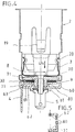
- la figure 4 est une vue en coupe du corps d'allumage pour un premier exemple de réalisation selon l'invention,
- la figure 5 est une vue partielle selon la
flèche 5 de la figure 4 montrant les moyens élastiques selon l'invention, - la figure 6 est une vue en coupe du corps d'allumage pour un second exemple de réalisation selon l'invention,
- la figure 7 est une vue partielle montrant l'échancrure pratiquée dans la première partie d'alimentation électrique selon l'exemple de réalisation de la figure 6,
- les figures 8,9,11 sont des vues partielles analogues à la figure 4 pour respectivement un troisième, un quatrième et un cinquième exemple de réalisation selon l'invention,
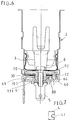
- la figure 10 est une vue partielle en coupe axiale pour un sixième exemple de réalisation selon l'invention,
- les figures 12 et 13 sont des vues analogues à la figure 4 pour encore d'autres variantes de réalisation.
- FIG. 1 is an exploded view in axial section of a cigar lighter according to the prior art,
- FIG. 2 is a sectional view of the resettable thermal circuit breaker with a positive temperature coefficient,
- FIG. 3 is a characteristic curve of the resistance as a function of the temperature of said resettable thermal circuit breaker,
- FIG. 4 is a sectional view of the ignition body for a first exemplary embodiment according to the invention,
- FIG. 5 is a partial view according to
arrow 5 in FIG. 4 showing the elastic means according to the invention, - FIG. 6 is a sectional view of the ignition body for a second embodiment according to the invention,
- FIG. 7 is a partial view showing the notch made in the first electrical supply part according to the embodiment of FIG. 6,
- FIGS. 8, 9, 11 are partial views similar to FIG. 4 for a third, a fourth and a fifth exemplary embodiment according to the invention, respectively.
- FIG. 10 is a partial view in axial section for a sixth exemplary embodiment according to the invention,
- Figures 12 and 13 are views similar to Figure 4 for yet other alternative embodiments.
Dans les figures 4 à 13, selon l'invention, la prise de courant appartient à un allume-cigares pour véhicule automobile et par convention on entend par pièce isolante une pièce électriquement isolante, telle que de la matière plastique, et par pièce conductrice une pièce en matériau électriquement conducteur, par exemple une pièce métallique.In Figures 4 to 13, according to the invention, the outlet belongs to a cigar lighter for a motor vehicle and by convention is meant by insulating part an electrically insulating part, such as plastic, and by conductive part a piece of electrically conductive material, for example a metallic piece.
Pour mémoire (figures 1 à 3) on rappellera qu'un allume-cigares comporte, d'une part, un bouchon amovible 1, formant une fiche de courant, pourvu d'une coupelle d'extrémité 11 recevant un corps électrique de chauffage 10 destiné à allumer une cigarette ou un cigare, et, d'autre part, un corps d'allumage creux 2, formant prise de courant, pourvu d'un élément de contact électrique 3, généralement un bilame d'accrochage 3, et de parties d'alimentation électriques, généralement des languettes 4,5, avec intervention de rondelles d'isolation électriques 6,7, assemblées entre elles par une vis 8.For the record (Figures 1 to 3) it will be recalled that a cigar lighter comprises, on the one hand, a
Le bouchon 1 se loge à coulissement à l'intérieur du corps 2 pour occuper soit une position de chauffage, soit une position de repos, ou être extrait.The
Pour ce faire le bouchon chauffant 1 présente un bouton 13 mobile et un pare-cendres 14 cranté, et le corps 2 des languettes de retenue 19.To do this, the
Ce bouchon 1 est normalement enfoncé dans le corps 2 et les languettes 19 retiennent le pare-cendres 14.This
En position de repos la coupelle 11 est au-dessus du bilame 3, tandis qu'en position de chauffage (bouton 13 enfoncé) la coupelle 11 coopère à accrochage avec le bilame 3.In the rest position the
Un circuit électrique est alors établi à travers le bilame 3 et le corps de chauffage 10 ; les lames du bilame 3 s'incurvant vers l'extérieur au fur et à mesure de l'échauffement jusqu'à désenclenchement de la coupelle 11 sous l'action d'un ressort de rappel 16 porté par le bouchon. Il ne reste plus qu'à l'usager à extraire le bouchon pour allumer sa cigarette.An electrical circuit is then established through the
Ainsi lorsque le bouton 13 est enfoncé un circuit électrique s'établit de la languette 5, reliée à la borne positive de la batterie du véhicule, à la languette 4 reliée à la borne négative de la batterie, à travers la vis 8, la coupelle 11, le corps de chauffage 10, l'organe 18, le bilame 3, la douille 17, le guide 15, le pare-cendres 14 et le corps 2, lesdites pièces étant en matériau conducteur.Thus when the
Dans certains cas, la coupelle 11, par exemple lorsqu'elle est mal positionnée, n'arrive pas à se désenclencher du bilame 3, et pour éviter une surchauffe de l'allume-cigares il est prévu un dispositif de protection contre les surchauffes inséré dans le circuit électrique de l'allume-cigares.In some cases, the
Dans le document EP-A-0 495 719, il s'agit d'un disjoncteur thermique réarmable 30 à coefficient de température positif permanent avec une résistance augmentant brusquement avec la température (figure 3).In document EP-A-0 495 719, this is a resettable
Ce disjoncteur 30, en forme de plaque, est par exemple un composant vendu sous la marque "PolySwich" par la Société "RAYCHEM" et comporte deux électrodes métalliques 31,32 disposées de part et d'autre d'une matrice 33 en polymère semi-conducteur (figure 2). Cette matrice contient des particules conductrices par exemple à base de carbone tel que du graphite.This
En cas de surchauffe, il se produit en quelque sorte un gonflement de la matrice avec séparation des particules conductrices, en sorte que ce disjoncteur passe très rapidement d'une très basse résistance à une résistance élevée consécutivement à une surintensité ou à une surchauffe provoquée par le corps de chauffage 10.In the event of overheating, there is a sort of swelling of the matrix with separation of the conductive particles, so that this circuit breaker goes very quickly from a very low resistance to a high resistance following an overcurrent or overheating caused by the
Pour réarmer le disjoncteur, il suffit d'ôter le bouchon 11. Le disjoncteur en refroidissant retrouve alors sa faible résistance, l'allume-cigares devenant à nouveau opérationnel sans qu'il soit nécessaire de remplacer un quelconque fusible.To reset the circuit breaker, simply remove the
En variante, le disjoncteur thermique réarmable à coefficient de température positif permanent peut être un composant en céramique à base de titanate de baryum. Dans tous les cas, il est nécessaire de prendre des précautions pour que la vis 8 ne provoque pas une pression trop importante sur le disjoncteur.Alternatively, the resettable thermal circuit breaker with permanent positive temperature coefficient may be a ceramic component based on barium titanate. In all cases, it is necessary to take precautions so that the
Ainsi suivant l'invention, une prise de courant, notamment pour véhicule automobile, du genre comportant un corps creux 2 conducteur avec un fond 9 pour réception d'une fiche de courant 1 et établissement d'un circuit électrique par l'intermédiaire de pièces portées par ledit corps, à savoir, d'un disjoncteur thermique réarmable 30 en contact avec le fond 9 du corps 2, d'une première partie d'alimentation électrique 4 au contact direct ou indirect dudit disjoncteur 30 en étant portée par une première pièce isolante électriquement 60, d'une seconde partie d'alimentation électrique 5 isolée de la première partie d'alimentation électrique 4 par ladite première pièce isolante 60 et reliée électriquement à un élément de contact électrique 3, propre à coopérer avec ladite fiche de courant 1 en étant portée par une seconde pièce isolante électriquement 70, pour isolation dudit élément de contact 3 par rapport au fond 9 du corps 2, dans lequel ladite seconde pièce isolante 70 et ledit élément de contact 3 sont montés à l'intérieur du corps 2, tandis que ledit disjoncteur 30, les première 4 et seconde 5 parties d'alimentation électriques ainsi que ladite première pièce isolante 60 sont montés à l'extérieur du corps 2, avec intervention de moyens d'assemblage 8,81 entre les pièces isolantes 60,70, est caractérisée en ce que ledit disjoncteur thermique réarmable 30 est soumis à l'action de moyens élastiques spécifiques à action axiale 80,180,280 prenant appui sur la première pièce isolante 60 pour action sur la première partie d'alimentation électrique 4 et serrage contrôlé dudit disjoncteur thermique entre le fond 9 du corps 2 et une partie de pression conductrice portée par ladite première partie d'alimentation électrique 4, et en ce que des moyens d'espacement 71,171,271 sont prévus pour maintenir la première pièce isolante 60 à distance du fond 9 du corps 2, en sorte de créer un limiteur de pression.Thus according to the invention, a socket outlet, in particular for a motor vehicle, of the kind comprising a hollow
Dans les figures 4 à 13, la première 60,600 et la seconde 70 pièce isolante sont avantageusement en matière plastique en étant de forme annulaire. En variante elles peuvent être en un autre matériau isolant.In Figures 4 to 13, the first 60,600 and the second 70 insulating part are advantageously made of plastic material being of annular shape. As a variant, they may be made of another insulating material.
La première pièce isolante 60,600 est avantageusement creuse pour protection desdits moyens élastiques selon l'invention, en étant plus haute que ceux-ci. Il est formé ainsi une cavité de protection et de logement pour les moyens élastiques et également le disjoncteur. Cette pièce 60,600 protège le disjoncteur 30 par masquage et sert également à immobiliser en rotation les première et seconde parties d'alimentation électriques, ici sous forme de languettes 4 et 5, avec des parties axiales s'étendant à l'extérieur du corps 2 de forme cylindrique et métallique.The first insulating part 60,600 is advantageously hollow for protection of said elastic means according to the invention, by being higher than these. There is thus formed a protective cavity and housing for the elastic means and also the circuit breaker. This part 60,600 protects the
Dans les formes de réalisation des figures 9,11,13 les moyens élastiques spécifiques à action axiale consistent en une rondelle Belleville 280 centrée intérieurement par la première pièce isolante 60,600 à la faveur d'une saillie isolante 62 (figure 9), 162 (figure 11), 362 (figure 13), issue du fond 65 (figure 9 et 11), 365 (figure 13) de ladite pièce isolante 60,600.In the embodiments of FIGS. 9,11,13 the specific elastic means with axial action consist of a Belleville
En variante on peut utiliser un ressort à boudin ou une rondelle élastique ondulée.As a variant, it is possible to use a coil spring or a wavy elastic washer.
Dans tout les cas on maîtrise bien le serrage du disjoncteur.In all cases, the tightening of the circuit breaker is well controlled.
Dans les formes de réalisation des figures 4,6,8,10,12 les moyens élastiques spécifiques à action axiale consistent en des pattes élastiquement déformables 80 (figures 4,6,10), 180 (figure 8), 380 (figure 12) issues directement de la première pièce isolante 60,600, en sorte que le nombre de pièces de la prise demeure inchangé.In the embodiments of Figures 4,6,8,10,12 the specific elastic means with axial action consist of elastically deformable lugs 80 (Figures 4,6,10), 180 (Figure 8), 380 (Figure 12) directly from the first insulating part 60,600, so that the number of parts of the socket remains unchanged.
Avantageusement ces pattes 80,180,380, saillantes axialement ver le fond 9 par rapport au fond 65,650 de la pièce 60,600, ont une forme éffilée pour augmenter leur souplesse et contact ponctuel par leur extrémité libre avec la base, décrite ci-après, de la languette 4.Advantageously, these tabs 80,180,380, projecting axially towards the bottom 9 relative to the bottom 65,650 of the part 60,600, have a tapered shape to increase their flexibility and punctual contact by their free end with the base, described below, of the
Dans la figure 13 la partie de pression conductrice est constituée par une pièce distincte électriquement conductrice 400 portée par la base de la languette 4.In FIG. 13, the conductive pressure part consists of a separate electrically
Dans les autres figures cette partie de pression, en contact dans tout les cas avec le disjoncteur 30,300, appartient directement à la languette 4, qui dans tous les cas, sous l'action des moyens élastiques 80,180,280,380 agissant sur elle, forme un organe presseur pour serrage du disjoncteur 30,300 entre la partie de pression et le fond 9 du corps 20.In the other figures, this pressure part, in any case in contact with the circuit breaker 30.300, belongs directly to the
Plus précisément la première languette 4 a globalement la forme d'une équerre avec une base horizontale au contact (figures 4 à 11) dudit disjoncteur 30 à coefficient de température positif permanent. Cette base constitue une plaque de pression et est soumise dans les figures 4 et 5 à l'action des pattes inclinées d'orientation axiale 80 issues de la première pièce isolante 60.More precisely, the
Ces pattes 80 élastiques font saillie axialement par rapport au fond 65 de la pièce 60 et ont une extrémité effilée. Ces pattes sollicitent la languette 4 vers le fond 9 pour serrage élastique contrôlé du disjoncteur 30 entre le fond 9 et la base de la languette 4.These
La languette 4 est montée mobile axialement, sous l'action des pattes 80, par rapport à la pièce 60 en étant liée en rotation à la pièce 60 par coopération de formes, la partie axiale de la languette 4 traversant pour ce faire une ouverture complémentaire 63 pratiquée dans le fond 65.The
Les pattes 80 interrompent localement le contour de la saillie creuse 62 de forme rectangulaire en étant plus haute que la saillie 62 pour contact avec la languette 4. Cette saillie 62, fractionnée par les pattes 80, est issue centralement du fond 65 en s'étendant axialement en direction du fond 9. La saillie 62 est propre à coopérer avec un nez saillant 71 isolant issu centralement de la seconde pièce 70. Ce nez traverse centralement une ouverture 91 du fond 9 ainsi que le disjoncteur 30 et la base de la languette 4 percés centralement à cet effet. Ce nez 71 a un contour de forme rectangulaire, tout comme les perçages des pièces 9,30,4, qu'il traverse de manière complémentaire et est propre à coopérer de manière complémentaire avec la saillie 62 en étant entouré par celle-ci. Ce nez 71 est percé centralement et est traversé par l'organe d'assemblage 8, ici une vis métallique, dont la tête prend appui sur la base du bilame 3. Cette vis traverse également la pièce 60 et est assemblée par vissage à la seconde languette 5 également en forme d'équerre. Cette languette 5 a une base munie d'un trou taraudé pour vissage de la vis 8 et est immobilisée en rotation par coopération de formes avec des saillies 61 issues de la pièce 60 et s'étendant en direction opposée du fond 9.The
Le bilame 3 est ainsi relié électriquement à la languette 5 par la vis 8 conductrice, tandis que la languette 5 est isolée de la languette 4 par contact avec le fond 65, les parties horizontales des languettes 4,5 étant disposées de part et d'autre du fond 65.The
La vis 8 permet un assemblage du bilame 3, serrée entre la tête de la vis 8 et la pièce 70, de la pièce 60 et de la languette 5 avec le fond 9.The
Les moyens d'espacement selon l'invention sont formés par ce nez 71 en appui sur le fond 65. Ainsi le serrage du disjoncteur 30, ici de faible épaisseur, est indépendant du serrage de la vis 8.The spacing means according to the invention are formed by this
Il est formé ainsi un limiteur de pression, en sorte que le disjoncteur ne risque pas de fluer, notamment lorsqu'il est à base de polymère semi-conducteur ("PolySwitch") et/ou de casser, notamment lorsqu'il est à base de céramique. En effet, la force de serrage dépend des pattes 80.A pressure relief valve is thus formed, so that the circuit breaker does not risk creeping, in particular when it is based on semiconductor polymer ("PolySwitch") and / or breaking, in particular when it is based of ceramic. Indeed, the clamping force depends on the
On appréciera que les diverses pièces sont fixes en rotation par coopération de formes. La pièce 70 est immobilisée en rotation par coopération du nez 71 avec l'ouverture 91 complémentaire.It will be appreciated that the various parts are fixed in rotation by cooperation of shapes. The
Ce nez 71 fixe en rotation la pièce 60 ainsi que le disjoncteur 30 et isole celui-ci de la vis 8.This
La languette 4 peut traverser à jeu l'ouverture 63 en étant fixée en rotation par le nez 71.The
On notera que le serrage du disjoncteur 30 peut être précis puisqu'il dépend de la distance entre les fonds 9,65 et donc de la longueur du nez 71.It will be noted that the tightening of the
En variante le nez 71 peut présenter deux méplats pour immobilisation en rotation de la pièce 70. Ce nez 171 (figure 6) peut être de forme annulaire comme les divers passages qu'il traverse, ainsi que le contour de la saillie 62.As a variant, the
En effet (figure 6) l'immobilisation en rotation des pièces 60,70 est effectuée par au moins un téton 72 issu latéralement de la pièce isolante 70 et traversant un passage 92 latéral du fond 9 pour s'engager dans une ouverture complémentaire 41 pratiquée dans la base de la languette 4.In fact (FIG. 6) the immobilization in rotation of the
Ainsi la pièce 70 fixe en rotation la languette 4 par coopération du téton 72 avec l'ouverture 41, tandis que la languette 4 fixe en rotation la pièce isolante 60 par coopération avec l'ouverture 63.Thus the
En variante, le téton 72 peut être inséré entre deux nervures 64 issues de la pièce 60 pour immobilisation en rotation des pièces isolantes.As a variant, the
Bien entendu (figure 8) l'organe d'assemblage conducteur des pièces 60,70 peut consister en un rivet 81, en variante un boulon, avec une tête maintenant le bilame 3 en contact avec la pièce 70 et un fût avec à son extrémité un trou borgne.Of course (FIG. 8) the conductive assembly member for the
Par déformation de l'extrémité du rivet 81 metallique (sertissage), on vient fixer la languette 5 au contact du fond 65 de la pièce 60. Les pattes élastiquement 180 sont distinctes de la saillie 62.By deformation of the end of the metallic rivet 81 (crimping), the
Ces pattes 180 inclinées vers la périphérie externe de la rondelle 60 ont une extrémité effilée et peuvent être au nombre de trois par exemple en étant plus longues que les pattes de la figure 4. La saillie 62 peut être continue et plus solide.These
La pression exercée sur le disjoncteur 30 est donc plus précise en étant moins influencée par les tolérances de fabrication. Ces pattes 180 sont facilement réalisables par moulage laissant apparaître un trou 181. Les pattes 180 sont plus hautes que la saillie 62.The pressure exerted on the
A la figure 9, la rondelle Belleville 280 présente une périphérie externe plane 281 comme à la figure 8, pour un bon contact avec la périphérie externe la base de la languette 4 et une bonne assise du disjoncteur 30, comme à la figure 8.In FIG. 9, the
La saillie 62 sert donc de centreur à la rondelle 280 en coopèrant avec la périphérie interne de la rondelle 280.The
Avantageusement, on choisi la courbe caractéristique de la rondelle 280 pour que celle-ci présente une partie plate, afin de s'affranchir des tolérances de fabrication et exercer une charge constante prédéterminée sur le disjoncteur 30. La pièce creuse 60 protège la rondelle 280 en étant plus haute que celle-ci.Advantageously, the characteristic curve of the
Bien entendu, on peut inverser les structures.Of course, we can reverse the structures.
Ainsi à la figure 10 le téton 172 est issu en saillie axiale de la pièce 60 et traverse l'ouverture 92 du fond 9 pour s'engager dans une échancrure 73 complémentaire de la pièce 70.Thus in FIG. 10, the
Les tétons 72 (figure 6), 172 (figure 10) peuvent constituer les moyens d'espacement le nez 171 étant alors raccouci.The pins 72 (Figure 6), 172 (Figure 10) may constitute the spacing means the nose 171 then being softened.
En effet on peut prévoir trois tétons 72,172, repartis à 180° les un par rapport aux autres, venant chacun en contact avec le fond 65 ou avec le fond d'un trou borgne de la pièce 70.Indeed, three nipples 72,172 can be provided, distributed at 180 ° one with respect to the others, each coming into contact with the bottom 65 or with the bottom of a blind hole in the
A la figure 11, les moyens d'espacement consistent en un prolongement de la saillie 162 traversant centralement pour ce faire la languette 4, le disjoncteur 30 et une ouverture 291 du fond 9. L'extrémité libre de la saillie 162 vient en appui sur la pièce 70 dont le nez 271 est raccourci et coopére avec la périphérie interne de la saillie 162.In FIG. 11, the spacing means consist of an extension of the
Le blocage en rotation est effectué par la saillie 162 à contour de forme rectangulaire par exemple coopérant de manière complémentaire avec l'ouverture 291 et le nez 271 conformés en conséquence.The rotation is blocked by the
En variante le blocage en rotation est effectué comme dans les figures 8 ou 10, la saillie 162 étant annulaire et le nez 271 cylindrique. La saillie 162 peut également coopérer, par son extrémité libre, directement avec le fond 9 et ne pas traverser celui-ci.As a variant, the blocking in rotation is carried out as in FIGS. 8 or 10, the
En variante la saillie 162 peut être solidaire du corps 2 en étant rapportée centralement sur le fond 9.As a variant, the
L'élément de contact 3 peut avoir uniquement une fonction d'accrochage du fait de la présence du disjoncteur thermique 30, celui-ci disjonctant automatiquement pour une température donnée, en sorte que l'utilisateur peut retirer le bouchon 1 lorsque le corps de chauffage 10 a atteint la température désirée ; un dispositif d'avertissement étant alors prévu.The
De même, on peut enfoncer dans le corps 2 une fiche d'un accessoire par exemple une fiche d'alimentation d'une lampe d'éclairage ou autre.Likewise, one can insert into the body 2 a plug of an accessory, for example a plug for supplying a lighting lamp or the like.
La prise de courant peut ne pas faire office de corps d'allumage d'allume-cigares en ayant une structure similaire. Dans ce cas, l'élément de contact 3 est simplifié et n'a plus une fonction de bilame et d'accrochage, tandis que le disjoncteur 30, assure une protection.The outlet may not act as a cigarette lighter ignition body with a similar structure. In this case, the
Les parties d'alimentation 4,5 peuvent avoir une autre forme, par exemple, leur partie axiale peut être conformée pour constituer une partie femelle.The
La languette 4 peut être reliée à la borne positive de la batterie et la languette 5 à la borne négative de celle-ci.The
Le nombre des organes d'assemblage 8,81 dépend des applications tout comme le serrage du disjoncteur, fonction de l'écartement entre les fonds 65,9.The number of assembly members 8.81 depends on the applications as does the tightening of the circuit breaker, a function of the spacing between the bottoms 65.9.
Ce serrage permet une surchauffe sans endommagement, notamment claquage, du disjoncteur et on notera que les perçages ou passages centraux des nez 71,171,271 sont évasés, ici de forme tronconique, en sorte que les organes 8,81 n'ont pas d'action de déformation nuisible sur les saillies 62,162 et les moyens élastiques 80, 180, 280. Bien entendu l'évasage est dirigé vers le fond 65 de la pièce 60.This tightening allows overheating without damage, in particular breakdown, of the circuit breaker and it will be noted that the holes or central passages of the noses 71,171,271 are flared, here of frustoconical shape, so that the
La première pièce isolante peut consister en une simple plaque rectangulaire pourvue de saillies 61,62,162..The first insulating part may consist of a simple rectangular plate provided with
La forme de la base de la languette 4 peut être quelconque.The shape of the base of the
Ainsi à la figure 12 la languette 4 présente une partie horizontale dotée centralement d'un seul tenant d'une cheminée 42 dirigée vers le fond 9 et traversée par le nez isolant 371 de la pièce 70.Thus in FIG. 12, the
Le nez 371 est épaulé et presente une portion de diamètre réduit entourée par la cheminée 42. Les moyens d'espacement sont constitués par le rebord 66 (ou jupe), périphérique d'orientation axiale, de la pièce 60 simplifiée. Un léger jeu existe alors entre le fond 65 et l'extrémité du nez 371. Les pattes élastiques 380 sont bombées et issues du fond 65 à la faveur de fentes. Ces pattes 380 éffilées prennent appui sur la partie centrale de la base de la languette 4 et sont dirigées vers l'axe de la prise. La pièce 60 est alors dépourvue de saillie.The
Le disjoncteur réarmable consiste en un disque bilame 300 troué centralement pour passage de la portion de diamètre réduit du nez 371. Ce disque 300 est pincé à sa périphérie interne entre deux appuis, à savoir, l'épaulement du nez et l'extrémité libre, avantageusement arrondie, de la cheminée 42 formant la partie de pression.The resettable circuit breaker consists of a
Il foncitonne comme décrit dans le document FR-A-2 377 579 auquel on se reportera, et présente donc deux métaux de coéfficient de dilatation différent en étant obtenu de manière habituelle, par exemple par laminage. Normalement le disque 300 embouti est en contact avec le fond 9 (figure 12) et en cas de chauffage, lorsque la température du disque atteint une valeur excessive, celui-ci cloque (et donc se retourne) ce qui a pour effet de couper immédiatement l'alimentation électrique du corps de chauffage 10. La bilame se refroidit alors et se réarme, en reprenant sa position initiale que lorsque sa température a diminuée d'une valeur suffissante. On appréciera que le pincement du disque 300 entre ses appuis se fait de manière précise et sans risque de déterioration grâce aux pattes 380 permettant un serrage contrôlé indépendant de l'organe de serrage 8.It functions as described in document FR-A-2 377 579 to which reference will be made, and therefore presents two metals with different coefficient of expansion by being obtained in the usual way, for example by rolling. Normally the stamped
A la figure 13 la première pièce isolante 600 forme un connecteur et le disque bilame 300 est pincé entre l'extrémité libre d'un nez court 471 de la seconde pièce isolante 70 et l'extrémité libre d'une cheminée appartenant à une pièce électriquement conductrice 400 portée par la languette 40 reliée à la masse de la batterie. Le connecteur 600, entoure l'autre languette 50 (relié à la borne positive de la batterie) et est fendue pour introduction de la partie horizontale de la languette 40 de forme tortueuse. Le connecteur présente un fond 650, de part et d'autre duquel s'étendent les parties horizontales des languettes 40, 50. La partie horizontale de la languette 40 est en contact indirect par la pièce 400, à section en forme de L, avec le disjoncteur 300 et est échancrée localement pour passage d'une cheminée 362 issue centralement du fond 650 et pénétrant à l'intérieur du nez 471 creusé à cet effet. Comme aux figures 9 et 11 la rondelle Belleville 280 prend appui sur le fond 650 et sollicite la languette 40 et la pièce 400 en direction du fond 9.In FIG. 13, the first insulating
C'est le rebord (ou jupe) du connecteur qui constitue les moyens d'espacement, le dit rebord présentant un épaulement 472 à cet effet. La cheminée 362 sert également de centreur à la rondelle 280.It is the rim (or skirt) of the connector which constitutes the spacing means, the said rim having a
Le corps 2 est fixé à la paroi du véhicule, de manière connue en soi, par l'intermédiaire d'une bague 500 conductrice de lumière en matière isolante. Le montage est réalisé par clipsage.The
En variante, la partie horizontale de la languette 4 ou 40 peut être échancrée à sa périphérie externe et être centrée à la faveur de protubérances issues de la pièce 60, 600 par coopération de formes des échancrures avec les dites protubérances. Il en est de même du disjoncteur de figures 4 à 11 en sorte que la présence d'un nez de centrage issues de l'une des pièces 60, 70 n'est pas impérative.As a variant, the horizontal part of the
Claims (16)
Applications Claiming Priority (2)
| Application Number | Priority Date | Filing Date | Title |
|---|---|---|---|
| FR9114671 | 1991-11-27 | ||
| FR9114671A FR2684053B1 (en) | 1991-11-27 | 1991-11-27 | POWER SOCKET, PARTICULARLY FOR MOTOR VEHICLES. |
Publications (3)
| Publication Number | Publication Date |
|---|---|
| EP0544591A2 true EP0544591A2 (en) | 1993-06-02 |
| EP0544591A3 EP0544591A3 (en) | 1993-10-06 |
| EP0544591B1 EP0544591B1 (en) | 1996-07-03 |
Family
ID=9419411
Family Applications (1)
| Application Number | Title | Priority Date | Filing Date |
|---|---|---|---|
| EP19920403177 Expired - Lifetime EP0544591B1 (en) | 1991-11-27 | 1992-11-25 | Electrical socket, especially for a motor vehicle |
Country Status (4)
| Country | Link |
|---|---|
| EP (1) | EP0544591B1 (en) |
| DE (1) | DE69211962T2 (en) |
| ES (1) | ES2090552T3 (en) |
| FR (1) | FR2684053B1 (en) |
Cited By (2)
| Publication number | Priority date | Publication date | Assignee | Title |
|---|---|---|---|---|
| US5831246A (en) * | 1994-09-02 | 1998-11-03 | Valeo | Lighter body for a cigar lighter, especially for motor vehicles |
| CN1044795C (en) * | 1994-01-12 | 1999-08-25 | 瓦雷欧·维申公司 | Igniting member for a cigarette lighter, particularly in a motor vehicle |
Citations (7)
| Publication number | Priority date | Publication date | Assignee | Title |
|---|---|---|---|---|
| US4058701A (en) * | 1974-05-14 | 1977-11-15 | Schoeller & Co. Elektrotechnische Fabrik Gmbh & Co. | Glow element arrangement for electric cigarette lighters |
| US4204109A (en) * | 1977-10-13 | 1980-05-20 | Sun Chemical Corporation | Automatic electric cigar lighter |
| FR2446741A2 (en) * | 1979-01-16 | 1980-08-14 | Iao Industrie Riunite Spa | ELECTRIC CIGARETTE LIGHTER FOR MOTOR VEHICLES |
| US4230931A (en) * | 1978-10-10 | 1980-10-28 | Sun Chemical Corporation | Electric cigar lighter |
| DE3240716A1 (en) * | 1981-11-04 | 1983-06-30 | Kabushiki Kaisha Tokai Rika Denki Seisakusho, Aichi | ELECTRIC CIGARETTE LIGHTER |
| US4544226A (en) * | 1984-04-09 | 1985-10-01 | Casco Products Corporation | Two-piece clamp shell for electric cigar lighter |
| DE3932602C1 (en) * | 1989-09-29 | 1990-04-26 | Schoeller & Co Elektrotechnische Fabrik Gmbh & Co, 6000 Frankfurt, De |
-
1991
- 1991-11-27 FR FR9114671A patent/FR2684053B1/en not_active Expired - Fee Related
-
1992
- 1992-11-25 DE DE1992611962 patent/DE69211962T2/en not_active Expired - Fee Related
- 1992-11-25 EP EP19920403177 patent/EP0544591B1/en not_active Expired - Lifetime
- 1992-11-25 ES ES92403177T patent/ES2090552T3/en not_active Expired - Lifetime
Patent Citations (7)
| Publication number | Priority date | Publication date | Assignee | Title |
|---|---|---|---|---|
| US4058701A (en) * | 1974-05-14 | 1977-11-15 | Schoeller & Co. Elektrotechnische Fabrik Gmbh & Co. | Glow element arrangement for electric cigarette lighters |
| US4204109A (en) * | 1977-10-13 | 1980-05-20 | Sun Chemical Corporation | Automatic electric cigar lighter |
| US4230931A (en) * | 1978-10-10 | 1980-10-28 | Sun Chemical Corporation | Electric cigar lighter |
| FR2446741A2 (en) * | 1979-01-16 | 1980-08-14 | Iao Industrie Riunite Spa | ELECTRIC CIGARETTE LIGHTER FOR MOTOR VEHICLES |
| DE3240716A1 (en) * | 1981-11-04 | 1983-06-30 | Kabushiki Kaisha Tokai Rika Denki Seisakusho, Aichi | ELECTRIC CIGARETTE LIGHTER |
| US4544226A (en) * | 1984-04-09 | 1985-10-01 | Casco Products Corporation | Two-piece clamp shell for electric cigar lighter |
| DE3932602C1 (en) * | 1989-09-29 | 1990-04-26 | Schoeller & Co Elektrotechnische Fabrik Gmbh & Co, 6000 Frankfurt, De |
Cited By (2)
| Publication number | Priority date | Publication date | Assignee | Title |
|---|---|---|---|---|
| CN1044795C (en) * | 1994-01-12 | 1999-08-25 | 瓦雷欧·维申公司 | Igniting member for a cigarette lighter, particularly in a motor vehicle |
| US5831246A (en) * | 1994-09-02 | 1998-11-03 | Valeo | Lighter body for a cigar lighter, especially for motor vehicles |
Also Published As
| Publication number | Publication date |
|---|---|
| ES2090552T3 (en) | 1996-10-16 |
| EP0544591B1 (en) | 1996-07-03 |
| FR2684053B1 (en) | 1997-08-01 |
| DE69211962T2 (en) | 1996-10-31 |
| FR2684053A1 (en) | 1993-05-28 |
| EP0544591A3 (en) | 1993-10-06 |
| DE69211962D1 (en) | 1996-08-08 |
Similar Documents
| Publication | Publication Date | Title |
|---|---|---|
| FR2786924A1 (en) | THERMAL FUSE | |
| EP0790146B1 (en) | Vehicle lighter with a protection device | |
| EP0544591B1 (en) | Electrical socket, especially for a motor vehicle | |
| EP0758961B1 (en) | Lighter body for a cigarette lighter, particularly in motor vehicles | |
| EP0688274B1 (en) | Igniting member for a cigarette lighter, particularly in a motor vehicle | |
| EP0495720B1 (en) | Cigarette lighter, especially for motor vehicles | |
| EP0699556B1 (en) | Cigarette lighter body, especially for motor vehicles | |
| EP0749376B1 (en) | Lighter body for a cigarette lighter, particularly in motor vehicles | |
| FR2858684A1 (en) | Heating pellet for electrical cigarette lighter, has push button to cause closing of electrical circuit that supplies electrical current to filament resistor, which includes lighting side that is parallel to insertion axis of pellet | |
| EP0592336B1 (en) | Connecting terminal for electric power equipment | |
| EP0511089B1 (en) | Cigar lighter, especially for motor vehicles | |
| FR2810598A1 (en) | THERMAL SAFETY CIGARETTE LIGHTER | |
| FR2521770A1 (en) | Fast-acting thermal cut=out for heating appliance - has fusible solder plug which causes two contacts to separate when its melting temp. is reached | |
| EP0206868A1 (en) | Thermal circuit interrupter | |
| FR2683100A1 (en) | Power socket with a resettable thermal circuit breaker, especially for motor vehicles | |
| CA2395930C (en) | Safety device for monitoring heat in electric connection installations | |
| FR2689326A1 (en) | Power plug of an accessory, associated with an ignition body of a cigarette lighter. | |
| FR2671767A1 (en) | Cigar lighter, particularly for motor vehicles | |
| FR2502078A1 (en) | Cigar lighter for vehicle - includes bimetallic terminal arms which releasably locate over electrical heating element, when predetermined temp. is exceeded | |
| FR2675749A1 (en) | Cigar lighter, particularly for motor vehicles | |
| EP0767743B1 (en) | Heating plug for a cigarette lighter, particularly in motor vehicles | |
| FR2655926A1 (en) | LIGHTER-IGNITION BODY AND AUXILIARY PLUG ASSOCIATED WITH SUCH BODY, IN PARTICULAR FOR MOTOR VEHICLES. | |
| FR2477268A1 (en) | THERMAL PROTECTION ELECTRIC CIGARETTE LIGHTER FOR MOTOR VEHICLES | |
| FR2681496A1 (en) | Shielded heating elements with electrical supply and method of manufacture of such elements | |
| FR2714873A1 (en) | Cigar lighter body for use in motor vehicle |
Legal Events
| Date | Code | Title | Description |
|---|---|---|---|
| PUAI | Public reference made under article 153(3) epc to a published international application that has entered the european phase |
Free format text: ORIGINAL CODE: 0009012 |
|
| AK | Designated contracting states |
Kind code of ref document: A2 Designated state(s): DE ES FR GB IT |
|
| PUAL | Search report despatched |
Free format text: ORIGINAL CODE: 0009013 |
|
| AK | Designated contracting states |
Kind code of ref document: A3 Designated state(s): DE ES FR GB IT |
|
| 17P | Request for examination filed |
Effective date: 19931006 |
|
| 17Q | First examination report despatched |
Effective date: 19951013 |
|
| GRAH | Despatch of communication of intention to grant a patent |
Free format text: ORIGINAL CODE: EPIDOS IGRA |
|
| GRAH | Despatch of communication of intention to grant a patent |
Free format text: ORIGINAL CODE: EPIDOS IGRA |
|
| GRAA | (expected) grant |
Free format text: ORIGINAL CODE: 0009210 |
|
| AK | Designated contracting states |
Kind code of ref document: B1 Designated state(s): DE ES FR GB IT |
|
| REF | Corresponds to: |
Ref document number: 69211962 Country of ref document: DE Date of ref document: 19960808 |
|
| GBT | Gb: translation of ep patent filed (gb section 77(6)(a)/1977) |
Effective date: 19960829 |
|
| ITF | It: translation for a ep patent filed |
Owner name: SOCIETA' ITALIANA BREVETTI S.P.A. |
|
| REG | Reference to a national code |
Ref country code: ES Ref legal event code: FG2A Ref document number: 2090552 Country of ref document: ES Kind code of ref document: T3 |
|
| REG | Reference to a national code |
Ref country code: ES Ref legal event code: FG2A Ref document number: 2090552 Country of ref document: ES Kind code of ref document: T3 |
|
| PLBE | No opposition filed within time limit |
Free format text: ORIGINAL CODE: 0009261 |
|
| STAA | Information on the status of an ep patent application or granted ep patent |
Free format text: STATUS: NO OPPOSITION FILED WITHIN TIME LIMIT |
|
| 26N | No opposition filed | ||
| PGFP | Annual fee paid to national office [announced via postgrant information from national office to epo] |
Ref country code: ES Payment date: 19991115 Year of fee payment: 8 |
|
| PGFP | Annual fee paid to national office [announced via postgrant information from national office to epo] |
Ref country code: GB Payment date: 19991119 Year of fee payment: 8 |
|
| PG25 | Lapsed in a contracting state [announced via postgrant information from national office to epo] |
Ref country code: GB Free format text: LAPSE BECAUSE OF NON-PAYMENT OF DUE FEES Effective date: 20001125 |
|
| PG25 | Lapsed in a contracting state [announced via postgrant information from national office to epo] |
Ref country code: ES Free format text: LAPSE BECAUSE OF NON-PAYMENT OF DUE FEES Effective date: 20001126 |
|
| GBPC | Gb: european patent ceased through non-payment of renewal fee |
Effective date: 20001125 |
|
| REG | Reference to a national code |
Ref country code: ES Ref legal event code: FD2A Effective date: 20011214 |
|
| PGFP | Annual fee paid to national office [announced via postgrant information from national office to epo] |
Ref country code: FR Payment date: 20051130 Year of fee payment: 14 |
|
| PGFP | Annual fee paid to national office [announced via postgrant information from national office to epo] |
Ref country code: DE Payment date: 20061108 Year of fee payment: 15 |
|
| PGFP | Annual fee paid to national office [announced via postgrant information from national office to epo] |
Ref country code: IT Payment date: 20061130 Year of fee payment: 15 |
|
| PG25 | Lapsed in a contracting state [announced via postgrant information from national office to epo] |
Ref country code: DE Free format text: LAPSE BECAUSE OF NON-PAYMENT OF DUE FEES Effective date: 20080603 |
|
| REG | Reference to a national code |
Ref country code: FR Ref legal event code: ST Effective date: 20080930 |
|
| PG25 | Lapsed in a contracting state [announced via postgrant information from national office to epo] |
Ref country code: FR Free format text: LAPSE BECAUSE OF NON-PAYMENT OF DUE FEES Effective date: 20071130 |
|
| PG25 | Lapsed in a contracting state [announced via postgrant information from national office to epo] |
Ref country code: FR Free format text: LAPSE BECAUSE OF NON-PAYMENT OF DUE FEES Effective date: 20061130 |
|
| PG25 | Lapsed in a contracting state [announced via postgrant information from national office to epo] |
Ref country code: IT Free format text: LAPSE BECAUSE OF NON-PAYMENT OF DUE FEES Effective date: 20071125 |