EP0544281B1 - Sensor probe for measuring hydrogen concentration in molten metal and method for measuring hydrogen concentration - Google Patents
Sensor probe for measuring hydrogen concentration in molten metal and method for measuring hydrogen concentration Download PDFInfo
- Publication number
- EP0544281B1 EP0544281B1 EP92120184A EP92120184A EP0544281B1 EP 0544281 B1 EP0544281 B1 EP 0544281B1 EP 92120184 A EP92120184 A EP 92120184A EP 92120184 A EP92120184 A EP 92120184A EP 0544281 B1 EP0544281 B1 EP 0544281B1
- Authority
- EP
- European Patent Office
- Prior art keywords
- sensor element
- molten metal
- hydrogen concentration
- sensor
- measuring
- Prior art date
- Legal status (The legal status is an assumption and is not a legal conclusion. Google has not performed a legal analysis and makes no representation as to the accuracy of the status listed.)
- Expired - Lifetime
Links
Images







Classifications
-
- G—PHYSICS
- G01—MEASURING; TESTING
- G01N—INVESTIGATING OR ANALYSING MATERIALS BY DETERMINING THEIR CHEMICAL OR PHYSICAL PROPERTIES
- G01N27/00—Investigating or analysing materials by the use of electric, electrochemical, or magnetic means
- G01N27/26—Investigating or analysing materials by the use of electric, electrochemical, or magnetic means by investigating electrochemical variables; by using electrolysis or electrophoresis
- G01N27/403—Cells and electrode assemblies
- G01N27/406—Cells and probes with solid electrolytes
- G01N27/411—Cells and probes with solid electrolytes for investigating or analysing of liquid metals
- G01N27/4118—Means for protecting the electrolyte or the electrodes
-
- G—PHYSICS
- G01—MEASURING; TESTING
- G01N—INVESTIGATING OR ANALYSING MATERIALS BY DETERMINING THEIR CHEMICAL OR PHYSICAL PROPERTIES
- G01N27/00—Investigating or analysing materials by the use of electric, electrochemical, or magnetic means
-
- G—PHYSICS
- G01—MEASURING; TESTING
- G01N—INVESTIGATING OR ANALYSING MATERIALS BY DETERMINING THEIR CHEMICAL OR PHYSICAL PROPERTIES
- G01N27/00—Investigating or analysing materials by the use of electric, electrochemical, or magnetic means
- G01N27/26—Investigating or analysing materials by the use of electric, electrochemical, or magnetic means by investigating electrochemical variables; by using electrolysis or electrophoresis
- G01N27/403—Cells and electrode assemblies
- G01N27/406—Cells and probes with solid electrolytes
- G01N27/411—Cells and probes with solid electrolytes for investigating or analysing of liquid metals
- G01N27/4112—Composition or fabrication of the solid electrolyte
- G01N27/4114—Composition or fabrication of the solid electrolyte for detection of gases other than oxygen
Definitions
- the present invention relates to a sensor probe for measuring a hydrogen concentration in molten metal and method for measuring hydrogen concentration in molten metal using said sensor probe.
- Conventional methods for measuring hydrogen concentration in molten metal are (1) the initial bubble method calculating the amount of hydrogen gas based on the pressure and temperature of sample at the time first bubble was formed on the surface of sample under reduced pressure, (2) the reduced pressure solidification method measuring the amount of hydrogen gas based on observation of formation of bubbles in the sample solidified under reduced pressure, comparing the specific gravity with that of the standard and the bubble formation on the cross section of the sample, and (3) the Telegas method injecting a small amount of gas into molten metal, collecting discharged gas after circulated in said molten metal and analyzing hydrogen gas in said discharged gas using a gas chromatography after the distribution of hydrogen gas in said discharged gas reached its equilibrium state.
- a sensor probe for measuring oxygen concentration in molten metal is known.
- the sensor probe comprises a reference electrode and a measuring electrode.
- the electrodes are surrounded by tubular sleeve which in use is inserted into the molten melt.
- the measurements should be carried out with high accuracy.
- Said proton conductive solid electrolyte with perovskite structure has composition such as SrCe 0.95 Yb 0.05 O 3-x , BaCe 0.9 Nb 0.1 O 3-x , CaZr 0.9 In 0.1 O 3-x and the like. And, said sleeve or holding cup is formed with gas-impermeable and non-porous ceramic material.
- said sealing material may be a non-porous glass sealing material having thermal expansion coefficient in range of 8.0 x 10 -6 to 10.0 x 10 -6 /°C close to those (8.5 x 10 -6 to 9.8 x 10 -6 /°C) of said solid electrolyte, for example SrCe 0.95 Yb 0.05 O 3-x , CaZr 0.9 In 0.1 O 3-x , BaCe 0.95 Y 0.05 O 3-x and the like in temperature range from 300 to 1100 °C at the time of use of sensor and having the fluidization point higher than the maximum temperature for use of sensor.
- This principle for measuring hydrogen concentration is based on detecting electromotive force of galvanic cell using proton conductive solid electrolyte.
- hydrogen concentration in molten metal can be measured from hydrogen concentration obtained when hydrogen concentration in the atmosphere reached in its equilibrium state.
- hydrogen concentration in molten metal can be continuously measured for longer period without direct contact of the sensor element made of solid electrolyte with molten metal.
- hydrogen concentration in said molten metal can be measured by only dipping the holder and the like of the sensor probe into molten metal (melt bath) and allows continuous measurement for longer period because the whole sensor element or at least the electromotive force measuring part of the sensor probe does not contact with molten metal.
- hydrogen concentration in molten metal can be measured by only detecting the electromotive force of the sensor element of sensor probe, it allows to make the size of measuring equipment smaller and to improve operational efficiency for use during the actual casting process.
- it is possible to reduce running cost necessary for measuring because gas circulation as required for the Telegas method is not needed.
- it is possible to provide an equipment for measuring hydrogen concentration in molten metal with smaller size, high accuracy and high reliability.
- the Telegas method although has a reputation for accurate measurement, can not be applied to the situation with fast flow of molten metal such as discharged gas treatment process.
- the sensor probe related to the present invention can be applied, without any difficulty, even to such situation with fast flow of molten metal to measure hydrogen concentration, therefore it has a wider application fields, and the present invention provides a very useful tool to all technical fields requiring the determination of hydrogen concentration.
- a sensor element 1 is formed as a tube enclosed at the one end.
- This sensor element 1 consists of proton conductive solid electrolyte with perovskite structure, for example SrCe 0.95 Yb 0.05 O 3-x , CaZr 0.9 In 0.1 O 3-x , BaCe 0.95 Y 0.05 O 3-x and the like.
- a reference electrode 2 and a measuring electrode 3 both made of Pt, Ni, conductive oxides or the like for example, are formed by seizure or baking.
- a mullite tube 4 for introducing the reference gas (gas containing a constant concentration of hydrogen) is inserted into said sensor element 1.
- a lead wire 5 made of Pt, Ni or the like is inserted into said tube 4.
- a mullite tube 6 painted with metal paste such as Pt, Ni or the like is inserted into said tube 4, and said lead wire 5 is pushed by the surface of said tube 6 painted with said metal paste towards said porous reference electrode 2 so that said porous reference electrode 2 is electrically connected to said lead wire 5.
- powdered glass sealing material 7 is placed on the opening part of the sensor element 1 and in the space between said tube 4 and said porous reference electrode 2, and this glass sealing material 7 is covered by ceramic adhesive 8 so that the sensor element 1 is firmly fixed to the tube 4.
- the reference electrode 2 is separated gas-tightly from outside atmosphere and also the atmosphere around the measuring electrode 3.
- sensor element 1 constructed as mentioned above is fixed to a holding cup 10 made of ceramic such as Si 3 N 4 and the like.
- This holder 10 is provided with a fixing part 12 on the opposite outer side of opening part 11, and a hole 13 is provided on the center of said fixing part 12 to insert into the sensor element 1.
- sensor element 1 is inserted into the holder 10 so that the outer surface of said sensor element 1 is extended in the holder 10.
- a mullite ceramic tube 14, for example, covering the outer surface of the tube 4 is placed with its lower end on the fixing part 12 of the holder 10, and the tube 14 is fixed with the ceramic adhesive 16 to the holder 10.
- Glass sealing material 15 is placed between the brim of the sensor element 1 and the central outer surface of the holder 10 and also between the fixing part 12 and the outer surface of the tube 14 to keep these parts in gas tight.
- an outer electrode 18 is firmly fixed by a lead wire 17 to electrically contact with the measuring electrode 3.
- This outer electrode 18 is made of material which is not reactive with a melt bath 19.
- the opening part 11 of the holding cup 10 is dipped into the melt bath 19 to form a space between the inner surface of the holder 10 and the melt bath 19 in the holder 10.
- the measuring electrode 3 is placed in this space, avoiding direct contact of the sensor element 1 to the melt bath 19.
- the outer electrode 18 connecting to the measuring electrode 3 into the melt bath 19 the measuring electrode 3 is electrically connected to the melt bath 19.
- the electric potential on the measuring electrode side of the sensor element 1 can be measured through the melt bath 19 of molten aluminum.
- the hydrogen partial pressure P H2 can be measured by the sensor element 1 using galvanic electromotive force. That is, by supplying the reference gas to the atmosphere around of the reference electrode 2 through the tube 4, the electromotive force E generated between the measuring electrode 3 contacting with gas in said space and the reference electrode 2 contacting with said reference gas in the sensor element 1 can be detected.
- the hydrogen partial pressure P H2 over the surface of molten metal is obtained from this electromotive force.
- the hydrogen concentration S dissolved in the molten metal is then obtained from this hydrogen partial pressure P H2 using said equation (3).
- the hydrogen concentration in the molten metal can be measured without dipping the sensor element 1 into the molten metal. Therefore, corrosion of the sensor element 1 by the molten metal can be avoided, and dissolved hydrogen concentration can be continuously measured for long period.
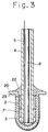
- a sensor element 20 has a slightly larger diameter than that of the sensor element 1 shown in Figure 1, and there exists a slight space between a mullite tube 4 and the inner surface of the sensor element 20.
- ceramic adhesive 21 embedded in the space the sensor element 20 and the tube 4 are fixed.
- powdered glass sealing material 23 is filled in the space between the tube 4 upper the ceramic adhesive 21 and the sensor element 20, and the sensor element 20 and the tube 4 are fixed at the opening part of the sensor element 20 with the ceramic adhesive 22. Thereby, powdered glass sealing material 23 is enclosed by adhesive 22.
- powdered glass sealing material 7 composition: Na 2 O 3 .B 2 O 3 .SiO 2 ; thermal expansion coefficient: 9.5 x 10 -6 ; softening point: 695°C; fluidization point : 880°C
- ceramic adhesive 8 was painted.
- sensor probe was heated in an electric furnace (heating and cooling rate: 5°C/second, keeping 10 minutes at 850°C) to fuse powdered glass sealing material 7.
- this probe was fixed to a silicon nitride holding cup 10 using powdered glass sealing material 15 and ceramic adhesive 16.
- the hydrogen concentration in aluminum melt bath 31 melted in a graphite crucible 30 was measured using this sensor probe.
- the hydrogen partial pressure over the aluminum melt bath 31 was adjusted by introducing a mixture containing Ar gas and hydrogen gas at various rate through a gas mixer 35 connected to an Ar gas source 37 and a hydrogen gas source 36.
- the hydrogen concentration in the molten metal was controlled at various values by placing the bath under the atmosphere of various hydrogen partial pressure, and the electromotive force of the sensor element 1 (or 20) was measured under these conditions.
- the temperature of molten metal and the electromotive force were recorded on a recorder 33.
- the molten metal in graphite crucible 30 was maintained at constant temperature by heating using a heater 34.
- the hydrogen concentration in the aluminum melt bath 31 was measured by the Telegas method using a gas chromatographic apparatus 38.
- nitrogen gas provided from a nitrogen gas source 40 was bubbled into the molten metal, and when the hydrogen concentration in the atmosphere over the surface of molten metal was reached in equilibrium with the hydrogen concentration in the molten metal, the atmospheric gas was introduced into the gas chromatographic apparatus 38 to measure the hydrogen concentration.
- Temperature in the melt bath 31 was measured using a K thermocouple and results were in the range of 700-800°C.
- the Telegas method used here is known as a method providing highly accurate values in determination of hydrogen concentration in molten metal.
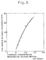
- Figure 5 shows a graph prepared by plotting hydrogen concentrations measured by the Telegas method on X-axis and electromotive forces of the sensor element on Y-axis. These data were obtained from 99 wt% pure aluminum solution bath maintained at 750°C. According to Figure 5, there exists very good co-relation between the hydrogen concentration in molten metal measured by the Telegas method and the electromotive force of the sensor element. Similar results can be obtained under different temperature conditions.
- Figure 6 represents a graph prepared by plotting hydrogen concentrations in molten metal measured by the Telegas method on X-axis and hydrogen concentrations measured by the sensor element of this embodiment on Y-axis for comparison. As Figure 6 clearly shows, there is good agreement between measurements obtained from the Telegas method and those from the sensor of this invention. Therefore, it is understood that the measurements by the sensor probe of this embodiment is highly accurate.
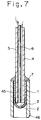
- Figure 7 shows a sectional view of a sensor probe for measuring dissolved hydrogen concentration according to the second embodiment of the present invention.
- Figure 7 all parts identical to those shown in Figures 1 and 2 are indicated by the same numerals without detail descriptions.
- a tube 4 made of a mullite tube for introducing the reference gas (with constant hydrogen concentration) is inserted into a sensor element 1, and a lead wire 5 made of Pt, Ni or the like is inserted into the tube 4. And, a mullite tube 6 is also inserted into this tube 4.
- the reference gas is supplied to the reference electrode 2 through the passage in the inner tube 6 and discharged from the atmosphere around the reference electrode 2 through the space between the inner tube 6 and the outer tube 4.
- the tube 4 is inserted into the sensor element 1 in a state that metal paste such as Pt, Ni or the like is painted on its lower end part. Thereby, the lower end part of lead wire 5 is caught by the tube 4 and the sensor element 1, and by pushing the lower end part of the lead wire 5 painted with said metal paste to the porous reference electrode 2, the lead wire 5 is being electrically connected to the porous reference electrode 2.
- This sleeve 45 is longer than the sensor element 1 and its upper level is coordinated to the upper level of the sensor element 1 with extending its lower end far downwards than the lower end of sensor element 1.
- Powdered glass sealing material 7 is placed in the opening part of the sensor element 1 to fill spaces between the gas inlet tube 4 and the sensor element 1 and the sleeve 45.
- the reference electrode 2 is separated gas-tightly from the outside atmosphere and from the atmosphere around the measuring electrode 3.
- lead 46 made of conductive paste is formed to electrically connect to the measuring electrode 3 of the sensor element 1, and the measuring electrode 3 is connected to a main measuring apparatus (not shown in the drawing) through this lead 46.
- the hydrogen concentration S dissolved in molten metal is calculated from this hydrogen partial pressure P H2 using said equation (3).
- hydrogen concentration in molten metal can be measured without dipping the sensor element 1 into molten metal. Therefore, corrosion of the sensor element 1 by molten metal can be avoided, and dissolved hydrogen concentration can be continuously measured for long period.
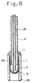
- Figure 8 shows a modified form of this embodiment.
- a tube 47 for discharging the reference gas of this sensor probe is made of stainless steel, therefore it is electroconductive.
- a porous platinum electrode was seized or baked on the inner and outer surfaces of a sensor element 1 made of CaZr 0.9 In 0.1 O 3-x of proton conductive solid electrolyte with perovskite structure and enclosed at the one end at temperature of 900°C. Then, an aluminum tube 4 and a stainless steel tube 47 with function as a lead wire were inserted into the sensor element 1.
- a mullite sleeve 45 was attached to the sensor element 1 so that its lower end is extending 10 mm downwards from the lower end level of the sensor element 1, and the tube 4, the sensor element 1 and the sleeve 45 were fixed by powdered glass sealing material 7 (composition: Na 2 O 3 .B 2 O 3 .SiO 2 ; thermal expansion coefficient: 9.5 x 10 -6 ; softening point: 695°C; fluidization point: 880°C).
- powdered glass sealing material 7 composition: Na 2 O 3 .B 2 O 3 .SiO 2 ; thermal expansion coefficient: 9.5 x 10 -6 ; softening point: 695°C; fluidization point: 880°C.
- powdered glass sealing material 7 composition: Na 2 O 3 .B 2 O 3 .SiO 2 ; thermal expansion coefficient: 9.5 x 10 -6 ; softening point: 695°C; fluidization point: 880°C.
- FIG. 9 all parts identical to those referred in Figures 7 and 8 are indicated using the same numerals, but they are not described in detail.
- the lower half of a sensor element 1 is filled with solid reference material 49.
- a ceramic insulating tube 47 is inserted into the upper part of the sensor element 1 to hold the sensor element 1 so that solid reference material 49 is sealed in the sensor element 1 by this insulating tube 47.
- the insulating tube 47 is fixed to the inner surface of the sensor element 1 by metal paste 48 such as Pt and the like.
- a lead wire 5 made of Pt, Ni or the like is inserted into the insulating tube 47.
- metal paste such as Pt, Ni or the like is painted, and by catching the lower end part of lead wire 5 with the insulating tube 47 and solid reference material 49, the lead wire 5 is electrically connected to solid reference material 49 by said metal paste.
- This sleeve 45 is longer than the sensor element 1 and its upper level is coordinated to the upper level of the sensor element 1, so that its lower end is extending downwards than the lower end of sensor element 1.
- Powdered glass sealing material 7 is placed in the opening part of the sensor element 1 to fill the space between the insulating tube 47, the sensor element 1 and the sleeve 45.
- the reference electrode 2 is separated gas-tightly from the outside atmosphere and from the atmosphere around the measuring electrode 3.
- lead 46 made of conductive paste is formed to electrically connect with the measuring electrode 3 of the sensor element 1, and the measuring electrode 3 is connected to a main measuring apparatus (not shown in the drawing) through this lead 46.
- solid reference material there are hydroxyapatite (Ca 10 (PO 4 ) 6 (OH) 2 ), aluminum phosphate (AlPO 4 ) and the like as described in Japanese Patent Application Laid Open No. 269053/1988.
- Figure 10 is a sectional view of a modified form of this embodiment.
- This sensor probe has a relatively longer sleeve 50 of which upper part is placed on higher level than the upper part of the sensor element 1. Therefore, glass sealing material 7 covers also the space between the sleeve 50 and the insulating tube 47 to improve its sealing performance.
- This embodiment has effect similar to that of the previous embodiment shown in Figure 9.
- a porous platinum electrode 2 and a measuring electrode 3 were seized or baked on the inner and outer surfaces of a sensor element 1 made of CaZr 0.9 In 0.1 O 3-x and enclosed at the one end at temperature of 900°C. Then, the sensor element 1 was filled with a mixture of AlPO 4 and La 0.4 Sr 0.6 CoO 3-x powders as solid reference material, an aluminum insulating tube 47 inserted with Pt lead wire and painted with Pt paste was inserted into the sensor element 1. Then, a sensor probe was manufactured as described in the previous embodiment shown in Figure 8.
- a sensor element 1 The upper part of a sensor element 1 is covered with a part of a fine ceramic tube 51 made of alumina, mullite or silicon nitride, for example, for introducing the reference gas (constant hydrogen concentration) and holding the sensor element, and a lead wire 5 made of Pt, Ni or the like is inserted into this tube 51.
- This lead wire 5 is electrically connected to the reference electrode 2 on the inner surface of the sensor element 1 by metal paste made of Pt, Ni or the like.
- a mullite tube 52 is inserted into the tube 51.
- the reference gas is supplied to the reference electrode 2 through the passage in the inner tube 52 and discharged from the atmosphere around the reference electrode 2 through the space between the outer tube 51 and the inner tube 52.
- glass sealing material 7 is placed on the space between the lower end of tube 51 and the sensor element 1, and this glass sealing material 7 is connecting to the tube 51 and the sensor element 1 and also keeping in gas-tight between both parts as well as between the reference electrode 2 and the outside atmosphere.
- On the outer surface of the tube 51 is painted with conductive paste 46 which is electrically connected to the measuring electrode 3 on the outer surface of the sensor element 1. By this, the measuring electrode 3 is connected to a signal processor through this conductive paste 46.
- a porous silicon carbide ceramic cup 53 is formed as a tube enclosed at its lower end and fixed to the tube 51 through ceramic adhesive 8 so that its open end is placed on the lower end of the tube 51.
- This cup 53 is made of porous silicon carbide (SiC) which is difficult to wet with molten metal.
- Said porous ceramic cup is made of materials through which molten metal is not permeable but only gas is permeable.
- silicon carbide with poor wettability to molten metal can be used.
- Such material which is poor wettable to molten metal is preferable due to lower permeability of molten metal into the cup.
- the hydrogen concentration S dissolved in molten metal is measured from this hydrogen partial pressure P H2 according to said equation (3).
- the hydrogen concentration in molten metal can be measured without dipping the sensor element 1 into molten metal. Therefore, corrosion of the sensor element 1 by molten metal can be avoided and the dissolved hydrogen concentration can be continuously measured for long period.
- Figure 12 is a sectional view of a modified form of this embodiment.
- a reference gas discharge tube 54 of this sensor probe is made of stainless steel, therefore it is an electroconductive. Then, by connecting electrically the reference electrode 2 on the inner surface of a sensor element 1 to the tube 54, the reference electrode 2 is electrically connected to a main measurement apparatus through the tube 54. Thereby, the lead wire 5 of the previous embodiment shown in Figure 11 can be eliminated.
- This embodiment has effect similar to that of the previous embodiment shown in Figure 1.
- an alumina tube 51 was inserted into a sensor element 1 manufactured as the aforementioned, then seized each other using powdered glass sealing material 7 (composition: Na 2 O 3 .B 2 O 3 .SiO 2 ; thermal expansion coefficient: 9.5 x 10 -6 ; softening point: 695°C; fluidization point: 880°C). Then, the sensor element 1 was covered by a porous silicon carbide cup 53 with pore size of 30 ⁇ m or less, and this cup was fixed to the tube 51 by ceramic adhesive.
- powdered glass sealing material 7 composition: Na 2 O 3 .B 2 O 3 .SiO 2 ; thermal expansion coefficient: 9.5 x 10 -6 ; softening point: 695°C; fluidization point: 880°C.
- the measuring electrode 3 is connected to a main measuring apparatus through this conductive paste 58.
- solid reference material 56 is filled to contact with the reference electrode 2.
- solid reference material 56 there are hydroxyapatite, aluminum phosphate and the like.
- the sensor element 1 is attached to the opening part of a porous ceramic cup 53 with poor wettability to molten metal. And, on both opening parts of this cup 53 and the sensor element 1, glass sealing material 7 is placed, and thereby both the reference electrode 2 and the measuring electrode 3 are sealed in gas-tight from each other and from the outside atmosphere.
- the cup 53 is fixed to the sensor element 1 and an appropriate space is formed between the cup 53 and the outer surface at the enclosed part of the sensor element 1.
- the hydrogen concentration P H2 in said space can be measured by the sensor element 1 using galvanic electromotive force.
- solid reference material 56 is used as the reference for galvanic electromotive force.
- solid reference material 56 a mixture of AlPO 4 and La 0.4 Sr 0.6 CoO 3-x powders was used.
- This sensor element 1 is placed in the sleeve 60 so that its opening lower end is slightly extending from the lower end of the sleeve 60, and the sleeve 60 and the sensor element 1 are fixed each other at the lower end of the sleeve 60 by glass sealing material 7.
- the reference electrode 2 is sealed in gas-tightly from the electrode 3 as well as from the outside atmosphere.
- this sleeve 60 On the inner surface of this sleeve 60, lead 62 made of conductive paste is formed to electrically connect to the measuring electrode 3 extending its open part slightly outside of the sensor element 1, and the measuring electrode 3 is connected to a main measuring apparatus (not shown in the drawing) through this lead 62.
- a part of mullite tube 61 for introduction of the reference gas (at constant hydrogen concentration) is inserted into the ceramic sleeve 60, and a lead wire 5 made of Pt, Ni or the like is inserted into this tube 61.
- This lead wire 5 is electrically connected to the porous reference electrode 2 through conductive paste 68, and the reference electrode 2 is connected to a main measurement apparatus through the lead wire 5.
- Each of the tubes 61 and 60 has a double tube structure.
- the reference gas is supplied to the reference electrode 2 through the passage in the inner tube 61 and discharged from the atmosphere around the reference electrode 2 through the passage formed between the outer tube 60 and the inner tube 61.
- the hydrogen partial pressure P H2 in this space is measured by the sensor element 1 using galvanic electromotive force. That is, the reference gas is supplied to and circulated around the reference electrode 2 using the tubes 61 and 60, the electromotive force E generated between the measuring electrode 3 contacting with gas in said space and the reference electrode 2 contacting with said reference gas is detected, and the hydrogen partial pressure P H2 over molten metal is obtained from this electromotive force using said equation (1).
- the hydrogen concentration S dissolved in molten metal is calculated from this hydrogen partial pressure P H2 using said equation (3).
- hydrogen concentration in molten metal can be measured without dipping the sensor element 1 into molten metal. Therefore, corrosion of the sensor element 1 by molten metal can be avoided, and dissolved hydrogen concentration can be continuously measured for long period.
- Figure 15 is a sectional view of a modified form of this embodiment.
- a reference gas discharge tube 63 of this sensor probe is made of stainless steel, therefore it is an electroconductive.
- the reference electrode 2 is electrically connected to a main measurement apparatus through the tube 63.
- the lead wire 5 of the previous embodiment shown in Figure 1 can be eliminated.
- This embodiment has effect similar to that of the previous embodiment shown in Figure 1.
- This lead wire 5 is electrically connected to a porous reference electrode 2 through conductive paste 66 made of Pt, Ni or the like, and the reference electrode 2 is connected to a main measuring apparatus through the lead wire 5.
- the insulating tube 67 is fixed to the holder 60 by glass sealing material 65. Further, a space between the insulating tube 67 and the holder 60 is sealed with this glass sealing material 65 in gas-tightly from the outside atmosphere.
- solid reference material 64 which is used as the reference of galvanic electromotive force is filled so that it contacts with the reference electrode 2.
- this solid reference material 64 hydroxyapatite, aluminum phosphate and the like can be used.
- hydrogen concentration in molten metal can be measured without dipping the formed part of the measuring electrode 3 of the sensor element 1, i.e. the electromotive force measuring part, into molten metal. Therefore, corrosion of the sensor element 1 by molten metal can be avoided, and dissolved hydrogen concentration can be continuously measured for long period.
- the alumina holder 60 was inserted into the sensor element 1 manufactured as described above, and the holder 60 and the element 1 were fixed with powdered glass sealing material 7 (composition: Na 2 O 3 .B 2 O 3 .SiO 2 ; thermal expansion coefficient: 9.5 x 10 -6 ; softening point: 695°C; fluidization point: 880°C).
- powdered glass sealing material 7 composition: Na 2 O 3 .B 2 O 3 .SiO 2 ; thermal expansion coefficient: 9.5 x 10 -6 ; softening point: 695°C; fluidization point: 880°C.
- solid reference material 64 a mixture of AlPO 4 and La 0.4 Sr 0.6 CoO 3-x powders was filled in the holder 60.
- SiC silicon carbide
- This filter 70 is fixed to the sensor element 1 by ceramic adhesive 71.
- This filter 70 is made of porous material with the average pore size of 30 ⁇ m or less.
- solid reference material 72 as the reference for galvanic electromotive force is filled to contact with the reference electrode 2.
- this solid reference material 72 hydroxyapatite, aluminum phosphate and the like can be used.
- the sensor element 1 is inserted with a ceramic sleeve 73 with openings at both sides.
- the upper end of this sleeve 73 is placed at the same level as the upper end of the sensor element 1, but its lower end is slightly extruding downwards than the lower end of the sensor element 1.
- glass sealing material 7 is placed on the upper parts of both sleeve 73 and sensor element 1, to keep in gas-tight the upper parts of the sleeve 73 and the sensor element 1 as well as the outer part of the ceramic insulating tube 76.
- lead 62 made of conductive paste is painted, and this lead 62 is connected to the measuring electrode 3 on the outer surface of the sensor element 1. Thereby, the measuring electrode 3 is connected to a signal processor through this lead 62.
- a porous ceramic filter 70 made of silicon carbide (SiC) with poor wettability to molten metal is attached to the lower opening part of the sleeve 73.
- SiC silicon carbide
- the sensor element 1 was attached to the alumina sleeve 73 about 10 mm longer than the sensor element 1, and they were fixed to the alumina insulating tube 76 with powdered glass sealing material 7 (composition: Na 2 O 3 .B 2 O 3 .SiO 2 ; thermal expansion coefficient: 9.5 x 10 -6 ; softening point: 695°C; fluidization point: 880°C) to seal the openings.
- powdered glass sealing material 7 composition: Na 2 O 3 .B 2 O 3 .SiO 2 ; thermal expansion coefficient: 9.5 x 10 -6 ; softening point: 695°C; fluidization point: 880°C
- the porous silicon carbide filter 70 with the average pore size of 15 ⁇ m and fixed to the opening part of the sensor element 1 with ceramic adhesive 71.
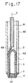
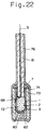
- a sensor element 1 is filled with ceramic fiber 80 such as alumina fiber and the like.
- a ceramic tube 60 is dipped into molten metal (not shown in Figure 19) so that a space separated from the outer atmosphere is formed in the sensor element 1. Because ceramic fiber 80 is filled in this sensor element 1, molten metal does not permeate into this sensor element 1, but gas can permeate into this sensor element 1. Because this gas phase is contacting with molten metal, hydrogen concentration in the gas phase reaches in equilibrium with hydrogen concentration in molten metal. Therefore, as mentioned above, the hydrogen concentration in molten metal can be measured without directly contact of the sensor element 1 with molten metal. Thus, corrosion of the sensor element 1 by molten metal can be avoided, and dissolved hydrogen concentration can be continuously measured for long period.
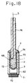
- ceramic fiber 80 such as alumina fiber and the like is filled in the extruded part of a sleeve 73.
- the operation of thus constructed sensor probe will be described.
- the lower part of the sleeve 73 is slightly dipped into molten metal (not shown in Figure 20). Thereby, the space surrounded by the sleeve 73 and the sensor element 1 contacts with molten metal. Therefore, the space in the ceramic fiber 80 is filled with gas phase contacting with this molten metal, and the measuring electrode 3 of the sensor element 1 contacts with this gas phase.
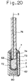
- metal film 81 in 10 to 1000 ⁇ m thick, made of Pt, Pd, Rh, Ni, Al and the like with superior wettability to molten metal is formed on the outer surface of a ceramic insulating tube 60 and the surface of glass sealing material 7.
- This metal film 81 can be formed also by seizure of the ceramic tube 60 painted with metal paste on its outer surface in an electric furnace. Also, the metal film 81 can be formed on the outer surface of the ceramic tube 60 by spraying said melted metal on the surface of ceramic tube.
- the hydrogen concentration in molten metal can be measured without direct contact of the sensor element 1 with molten metal. Therefore, corrosion of the sensor element 1 can be avoided and dissolved hydrogen concentration can be continuously measured for long period.
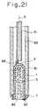
- metal film 81 with superior wettability to molten metal is formed in the same manner as the embodiment shown in Figure 21.
- the operation of thus constructed sensor probe will be described.
- the lower end of the sleeve 28 is dipped into molten metal (not shown in the drawing). Thereby, a space surrounded by the sleeve 73 and the sensor element 1 contacts with molten metal. Therefore, gas phase contacting with this molten metal saturates in the ceramic fiber 80, and the measuring electrode 3 of the sensor element 1 contacts with this gas phase.
Landscapes
- Chemical & Material Sciences (AREA)
- Health & Medical Sciences (AREA)
- Life Sciences & Earth Sciences (AREA)
- General Health & Medical Sciences (AREA)
- Physics & Mathematics (AREA)
- Electrochemistry (AREA)
- Analytical Chemistry (AREA)
- Biochemistry (AREA)
- Chemical Kinetics & Catalysis (AREA)
- General Physics & Mathematics (AREA)
- Immunology (AREA)
- Pathology (AREA)
- Molecular Biology (AREA)
- Measuring Oxygen Concentration In Cells (AREA)
- Investigating And Analyzing Materials By Characteristic Methods (AREA)
- Investigating Or Analyzing Non-Biological Materials By The Use Of Chemical Means (AREA)
Abstract
Description
SrCe0.95Yb0.05O3-x, BaCe0.9Nb0.1O3-x, CaZr0.9In0.1O3-x and the like. And, said sleeve or holding cup is formed with gas-impermeable and non-porous ceramic material. In case sealing is made in the time of manufacturing the sensor, said sealing material may be a non-porous glass sealing material having thermal expansion coefficient in range of 8.0 x 10⁻⁶ to 10.0 x 10⁻⁶ /°C close to those (8.5 x 10⁻⁶ to 9.8 x 10⁻⁶ /°C) of said solid electrolyte, for example SrCe0.95Yb0.05O3-x, CaZr0.9In0.1O3-x, BaCe0.95Y0.05O3-x and the like in temperature range from 300 to 1100 °C at the time of use of sensor and having the fluidization point higher than the maximum temperature for use of sensor. On the other hand, in case sealing is made just before use of sensor, it is desirable to use a non-porous glass sealing material having the softening temperature lower than use temperature of sensor and the fluidization point higher than use temperature of sensor.
Claims (14)
- A sensor probe for measuring hydrogen concentration in molten metal, comprising:a tubular sensor element (1, 20) made of proton conductive solid electrolyte with perovskite structure and closed at its one end,a reference electrode (2) made of porous electrode material formed on the inner surface of said sensor element (1, 20),a measuring electrode (3) made of porous electrode material formed on the outer surface of said sensor element (1, 20),sealing material (7) separating gas-tightly said reference electrode (2) from the outside atmosphere and the atmosphere around said measuring electrode (3),a ceramic sleeve or holding cup (10, 45, 73) fixed on the outer surface of said sensor element (1, 20) so that at least a part of said measuring electrode (3) on the outer surface of said sensor element (1, 20) is extending in the sleeve or holding cup (10, 45, 73), andmeans (4, 6, 47, 52, 54, 61, 63 ; 49, 56, 64, 72) for supplying a reference partial hydrogen pressure to said reference electrode as reference for a galvanic electromotive force generated between said reference and measuring electrodes (2, 3).
- A sensor probe for measuring hydrogen concentration in molten metal, comprising:a tubular sensor element (1) made of proton conductive solid electrolyte with perovskite structure and closed at its one end,a reference electrode (2) made of porous electrode material formed on the inner surface of this sensor element (1),a measuring electrode (3) made of porous electrode material formed on outer surface of said sensor element (1),sealing material (7) separating gas-tightly said reference electrode (2) from the outside atmosphere and the atmosphere around said measuring electrode (3),a porous ceramic cup (53) enclosing said sensor element (1) in such way of forming a space between said ceramic cup (53) and said sensor element (1), said porous ceramic cup (53) having properties that for molten metal it is not permeable, but only for gas it is permeable, andmeans (4, 6, 47, 52, 54, 61, 63 ; 49, 56, 64, 72) for supplying a reference partial hydrogen pressure to said reference electrode as reference for a galvanic electromotive force generated between said reference and measuring electrodes (2, 3).
- A sensor probe for measuring hydrogen concentration in molten metal, comprising:a tubular sensor element (1) made of proton conductive solid electrolyte with perovskite structure and closed at its one end,a reference electrode (2) made of porous electrode material formed on the outer surface of said sensor element (1),a measuring electrode (3) made of porous electrode material formed on the inner surface of said sensor element (1),a sealing member (7) separating gas-tightly said reference electrode (2) from the outside atmosphere and the atmosphere around the measuring electrode (3),a holding member or sleeve (60) fixed on the outer surface of said sensor element (1) in such a way that the opening part of said sensor element (1) is slightly extending from said holding member or sleeve (60), andmeans (4, 6, 47, 52, 54, 61, 63, 49, 56, 64, 72) for supplying a reference partial hydrogen pressure to said reference electrode as reference for a galvanic electromotive force generated between said reference and measuring electrodes (2, 3).
- The sensor probe according to one of claims 1 to 3, wherein means (4, 6, 47; 51, 52, 54; 61, 63) for supplying a reference partial hydrogen pressure to said reference electrode (2) introduces said reference hydrogen into said sensor element (1, 20).
- The sensor probe according to one of claims 1 to 3, comprising :
solid reference material (49, 56) filled in said sensor element (1) to contact with said reference electrode (2) as the reference for galvanic electromotive force. - The sensor probe according to one of claims 1 to 5,
characterized by:
a gas permeable porous filter (70) provided on the opening part of said sensor element (1) to prevent penetration of molten metal into the sensor element. - The sensor probe according to claim 1,
characterized by:
a ceramic fiber (80) filled in the part of said sleeve (73) or holding cup that is extruded from said sensor element to prevent the penetration of molten metal into said sleeve (73) or holding cup. - The sensor probe according to one of claims 1 to 6,
characterized by further comprising:
a ceramic fiber (80) filled in said sensor element (1) to prevent penetration of molten metal into the sensor element. - The sensor probe according to one of claims 1 to 8,
characterized by:
a film (81) covering the outer surface of part of said holding member or sleeve (60) and said sensor element (1) to be dipped into molten metal to increase the wettability of said holding member or sleeve and said sensor element with molten metal. - The sensor probe according to claim 9,
characterized in that
said film (81) is a metal film with thickness of 3 µm or more. - The sensor probe according to claim 2,
characterized in that
said porous ceramic cup (53) is silicon carbide. - The sensor probe according to claim 2,
characterized in that
said porous ceramic cup (53) has its pore size of 30 µm or less. - A method for measuring hydrogen concentration in molten metal using said sensor probe according to claim 1,
characterized by the steps of:dipping said sleeve or holding cup (10, 45, 73) of said sensor probe into molten metal (19, 31) by facing its opening part downwards, thereby enclosing a space contacting with said molten metal (19, 31) in said sleeve or holding cup (10, 45, 73), andmeasuring the hydrogen concentration in a gas atmosphere in said space using the galvanic electromotive force generated between said reference electrode (2) and measuring electrode (3) of said sensor probe after the hydrogen concentration in gas atmosphere reached nearly equilibrium with the hydrogen concentration in said molten metal (19, 31). - A method for measuring hydrogen concentration in molten metal using said sensor probe according to claim 3,
characterized by the steps of:placing a part of opening end of sensor element (1) of said sensor probe into molten metal, thereby enclosing a space contacting with said molten metal in said sensor element (1), andmeasuring the hydrogen concentration in a gas atmosphere in said space using the galvanic electromotive force generated between said reference electrode (2) and measuring electrode (3) of said sensor probe.
Applications Claiming Priority (20)
| Application Number | Priority Date | Filing Date | Title |
|---|---|---|---|
| JP310984/91 | 1991-11-26 | ||
| JP3310984A JPH0792449B2 (en) | 1991-11-26 | 1991-11-26 | Sensor probe for measuring amount of dissolved hydrogen in molten metal and method for measuring hydrogen concentration |
| JP3347386A JP2530076B2 (en) | 1991-12-27 | 1991-12-27 | Sensor probe for measuring the amount of dissolved hydrogen in molten metal and method of using the same |
| JP347386/91 | 1991-12-27 | ||
| JP347383/91 | 1991-12-27 | ||
| JP3347388A JPH07119729B2 (en) | 1991-12-27 | 1991-12-27 | Sensor probe for measuring the amount of hydrogen dissolved in molten metal |
| JP3347387A JP2578544B2 (en) | 1991-12-27 | 1991-12-27 | Sensor probe for measuring the amount of dissolved hydrogen in molten metal |
| JP347385/91 | 1991-12-27 | ||
| JP3347385A JP2578543B2 (en) | 1991-12-27 | 1991-12-27 | Sensor probe for measuring the amount of hydrogen dissolved in molten metal and method of using the same |
| JP3347383A JP2578542B2 (en) | 1991-12-27 | 1991-12-27 | Sensor probe for measuring the amount of dissolved hydrogen in molten metal |
| JP347388/91 | 1991-12-27 | ||
| JP347387/91 | 1991-12-27 | ||
| JP347384/91 | 1991-12-27 | ||
| JP3347384A JPH07119728B2 (en) | 1991-12-27 | 1991-12-27 | Sensor probe for measuring the amount of hydrogen dissolved in molten metal |
| JP4013469A JPH07119731B2 (en) | 1992-01-28 | 1992-01-28 | Sensor probe for measuring the amount of hydrogen dissolved in molten metal |
| JP13468/92 | 1992-01-28 | ||
| JP4013468A JPH07119730B2 (en) | 1992-01-28 | 1992-01-28 | Sensor probe for measuring the amount of hydrogen dissolved in molten metal |
| JP4013470A JPH07119732B2 (en) | 1992-01-28 | 1992-01-28 | Sensor probe for measuring the amount of hydrogen dissolved in molten metal |
| JP13469/92 | 1992-01-28 | ||
| JP13470/92 | 1992-01-28 |
Publications (2)
| Publication Number | Publication Date |
|---|---|
| EP0544281A1 EP0544281A1 (en) | 1993-06-02 |
| EP0544281B1 true EP0544281B1 (en) | 1998-06-03 |
Family
ID=27579634
Family Applications (1)
| Application Number | Title | Priority Date | Filing Date |
|---|---|---|---|
| EP92120184A Expired - Lifetime EP0544281B1 (en) | 1991-11-26 | 1992-11-26 | Sensor probe for measuring hydrogen concentration in molten metal and method for measuring hydrogen concentration |
Country Status (7)
| Country | Link |
|---|---|
| US (2) | US5439579A (en) |
| EP (1) | EP0544281B1 (en) |
| KR (1) | KR970003280B1 (en) |
| AT (1) | ATE166973T1 (en) |
| AU (1) | AU654219B2 (en) |
| CA (1) | CA2083909C (en) |
| DE (1) | DE69225778T2 (en) |
Cited By (1)
| Publication number | Priority date | Publication date | Assignee | Title |
|---|---|---|---|---|
| WO2017080005A1 (en) * | 2015-11-12 | 2017-05-18 | 东北大学 | Sensor and method for measuring content of hydrogen in metal melt |
Families Citing this family (21)
| Publication number | Priority date | Publication date | Assignee | Title |
|---|---|---|---|---|
| DK171537B1 (en) * | 1994-08-17 | 1996-12-23 | Topsoe Haldor As | Ion selective ceramic membrane and its use |
| KR0165651B1 (en) * | 1995-09-28 | 1999-03-30 | 모리시타 요이치 | Electrochemical devices |
| JP3311218B2 (en) * | 1995-11-02 | 2002-08-05 | 松下電器産業株式会社 | Hydrocarbon sensor |
| DE19652596C2 (en) * | 1996-12-18 | 1999-02-25 | Heraeus Electro Nite Int | Method and immersion probe for measuring electrochemical activity |
| US5884053A (en) * | 1997-06-11 | 1999-03-16 | International Business Machines Corporation | Connector for higher performance PCI with differential signaling |
| BE1011776A3 (en) * | 1998-03-06 | 2000-01-11 | Vito | Sensor for use in metal melt. |
| US7306951B1 (en) * | 1999-06-08 | 2007-12-11 | Midwest Research Institute | Method and apparatus for determining diffusible hydrogen concentrations |
| GB9921489D0 (en) * | 1999-09-10 | 1999-11-17 | Univ Cambridge Tech | Sensor probe |
| DE10103701C1 (en) * | 2001-01-26 | 2002-09-12 | Heraeus Electro Nite Int | Measuring device for determining the oxygen activity in metal melts or slag melts |
| EP1376117A4 (en) * | 2001-04-03 | 2006-05-10 | Tyk Corp | HYDROGEN TYPE CONCENTRATION CELL SENSOR AND PROCESS FOR PREPARING SOLID ELECTROLYTE THAT CAN DRIVE A PROTON |
| US7045231B2 (en) * | 2002-05-22 | 2006-05-16 | Protonetics International, Inc. | Direct hydrocarbon reforming in protonic ceramic fuel cells by electrolyte steam permeation |
| GB0221393D0 (en) * | 2002-09-14 | 2002-10-23 | Univ Cambridge Tech | Hydrogen sensing apparatus and method |
| US7332237B2 (en) * | 2003-01-27 | 2008-02-19 | Protonetics International, Inc. | Stream reforming of solid carbon in protonic ceramic fuel cells |
| US7255949B2 (en) | 2004-05-25 | 2007-08-14 | Protonetics International, Inc. | Systems and methods to generate hydrogen and electrical power in a reversible compound fuel cell |
| GB0421868D0 (en) * | 2004-10-01 | 2004-11-03 | Environmental Monitoring And C | Apparatus and method for measuring hydrogen concentration |
| EP1953765A4 (en) * | 2005-11-22 | 2010-03-17 | Nippon Sheet Glass Co Ltd | Proton conductive material, process for producing the same, hydrogen concentration cell, hydrogen sensor and fuel cell |
| DE102005060493B3 (en) | 2005-12-15 | 2006-11-30 | Heraeus Electro-Nite International N.V. | Test probe, for taking measurements in metal melt, comprises refractory material that covers forward part of bath contact but not rearward part |
| DE102007004147A1 (en) | 2007-01-22 | 2008-07-24 | Heraeus Electro-Nite International N.V. | Method for influencing the properties of cast iron and oxygen sensor |
| US9128005B2 (en) * | 2012-10-01 | 2015-09-08 | General Electric Company | Metalized ceramic leading edge nozzle Kiels for high-temperature turbine applications |
| WO2014087125A1 (en) | 2012-12-07 | 2014-06-12 | Environmental Monitoring And Control Limited | Method and apparatus for monitoring gas concentration |
| JP7265007B2 (en) * | 2019-07-01 | 2023-04-25 | 東京窯業株式会社 | Solid reference material and hydrogen gas sensor |
Citations (1)
| Publication number | Priority date | Publication date | Assignee | Title |
|---|---|---|---|---|
| JPH01291155A (en) * | 1988-05-18 | 1989-11-22 | Norihiko Taketsu | Method of measuring concentration of hydrogen |
Family Cites Families (15)
| Publication number | Priority date | Publication date | Assignee | Title |
|---|---|---|---|---|
| US3486997A (en) * | 1966-12-22 | 1969-12-30 | Beckman Instruments Inc | Reference electrode |
| US3565769A (en) * | 1967-10-17 | 1971-02-23 | United Nuclear Corp | Method and apparatus for determination of hydrogen content in a high temperature fluid |
| US3598711A (en) * | 1967-11-15 | 1971-08-10 | Bailey Meter Co | Electrochemical oxygen analyzer |
| US3773641A (en) * | 1968-12-23 | 1973-11-20 | G Fitterer | Means for determining the oxygen content of liquid metals |
| US3657096A (en) * | 1969-12-19 | 1972-04-18 | Leeds & Northrup Co | Reference electrode construction |
| US3791954A (en) * | 1970-08-06 | 1974-02-12 | Ngk Insulators Ltd | Device for measuring oxygen concentration of molten metal |
| US3871981A (en) * | 1971-09-01 | 1975-03-18 | Bailey Meter Co | In-situ oxygen detector |
| US3864231A (en) * | 1972-01-31 | 1975-02-04 | Metallurgie Hoboken | Apparatus for measuring in a continuous manner oxygen in a molten metal |
| US4007106A (en) * | 1973-06-22 | 1977-02-08 | Canadian Patents And Development Limited | Device for measuring oxygen concentration in molten-metal |
| CA990352A (en) * | 1974-08-02 | 1976-06-01 | Noranda Mines Limited | Apparatus for the continuous measurement of the oxygen content of molten copper or alloys thereof |
| US4151060A (en) * | 1978-02-01 | 1979-04-24 | Westinghouse Electric Corp. | Solid state filter for gas sensors |
| US4430192A (en) * | 1981-03-06 | 1984-02-07 | Yokogawa Hokushin Electric Corporation | Oxygen gas analyzer using solid electrolyte |
| US4627892A (en) * | 1985-02-22 | 1986-12-09 | University Patents, Inc. | Electrochemical sensors and methods for their manufacture and use |
| GB8602543D0 (en) * | 1986-02-03 | 1986-03-12 | Atomic Energy Authority Uk | Sensor |
| US4882032A (en) * | 1988-06-27 | 1989-11-21 | General Motors Corporation | Hydrogen probe |
-
1992
- 1992-11-17 KR KR1019920021565A patent/KR970003280B1/en not_active Expired - Fee Related
- 1992-11-23 AU AU28557/92A patent/AU654219B2/en not_active Ceased
- 1992-11-25 US US07/981,873 patent/US5439579A/en not_active Expired - Lifetime
- 1992-11-26 EP EP92120184A patent/EP0544281B1/en not_active Expired - Lifetime
- 1992-11-26 DE DE69225778T patent/DE69225778T2/en not_active Expired - Fee Related
- 1992-11-26 AT AT92120184T patent/ATE166973T1/en not_active IP Right Cessation
- 1992-11-26 CA CA002083909A patent/CA2083909C/en not_active Expired - Fee Related
-
1994
- 1994-09-08 US US08/302,604 patent/US5445725A/en not_active Expired - Lifetime
Patent Citations (1)
| Publication number | Priority date | Publication date | Assignee | Title |
|---|---|---|---|---|
| JPH01291155A (en) * | 1988-05-18 | 1989-11-22 | Norihiko Taketsu | Method of measuring concentration of hydrogen |
Cited By (3)
| Publication number | Priority date | Publication date | Assignee | Title |
|---|---|---|---|---|
| WO2017080005A1 (en) * | 2015-11-12 | 2017-05-18 | 东北大学 | Sensor and method for measuring content of hydrogen in metal melt |
| EP3372998A4 (en) * | 2015-11-12 | 2018-09-19 | Northeastern University | Sensor and method for measuring content of hydrogen in metal melt |
| US10598629B2 (en) | 2015-11-12 | 2020-03-24 | Northeastern University | Sensor and measurement method for measuring hydrogen content in metal melt |
Also Published As
| Publication number | Publication date |
|---|---|
| KR930010545A (en) | 1993-06-22 |
| DE69225778T2 (en) | 1998-11-19 |
| ATE166973T1 (en) | 1998-06-15 |
| AU654219B2 (en) | 1994-10-27 |
| US5445725A (en) | 1995-08-29 |
| CA2083909A1 (en) | 1993-05-27 |
| AU2855792A (en) | 1993-07-08 |
| US5439579A (en) | 1995-08-08 |
| KR970003280B1 (en) | 1997-03-17 |
| EP0544281A1 (en) | 1993-06-02 |
| DE69225778D1 (en) | 1998-07-09 |
| CA2083909C (en) | 1996-09-03 |
Similar Documents
| Publication | Publication Date | Title |
|---|---|---|
| US5439579A (en) | Sensor probe for measuring hydrogen concentration in molten metal | |
| EP0295798B1 (en) | Probe for determination of gas concentration in molten metal | |
| JPH0829375A (en) | Sensor for measuring the amount of hydrogen dissolved in molten metal | |
| EP1060392B1 (en) | Sensor for application in molten metals | |
| US4639304A (en) | Apparatus for determination of aluminum oxide content of the cryolite melt in aluminum electrolysis cells | |
| JPH0720082A (en) | Sensor probe for measuring the amount of hydrogen dissolved in molten metal | |
| JPH0835947A (en) | Sensor for measuring the amount of hydrogen dissolved in molten metal | |
| JP2878603B2 (en) | Sensor for measuring dissolved amount of hydrogen in molten metal | |
| JP2578544B2 (en) | Sensor probe for measuring the amount of dissolved hydrogen in molten metal | |
| JP2530076B2 (en) | Sensor probe for measuring the amount of dissolved hydrogen in molten metal and method of using the same | |
| JPH0675055B2 (en) | Method for measuring hydrogen concentration in molten metal and sensor probe used for the same | |
| JP2578542B2 (en) | Sensor probe for measuring the amount of dissolved hydrogen in molten metal | |
| JPH0792449B2 (en) | Sensor probe for measuring amount of dissolved hydrogen in molten metal and method for measuring hydrogen concentration | |
| JPH07119732B2 (en) | Sensor probe for measuring the amount of hydrogen dissolved in molten metal | |
| JPH0720083A (en) | Sensor probe for measuring the amount of hydrogen dissolved in molten metal | |
| JPH0829376A (en) | Sensor for measuring the amount of hydrogen dissolved in molten metal | |
| JPH0749331A (en) | Sensor probe for measuring the amount of hydrogen dissolved in molten metal | |
| JPH07119728B2 (en) | Sensor probe for measuring the amount of hydrogen dissolved in molten metal | |
| JPH0829379A (en) | Sensor for measuring the amount of hydrogen dissolved in molten metal | |
| CN114072665A (en) | Solid reference substance and hydrogen sensor | |
| JPH0829377A (en) | Sensor for measuring the amount of hydrogen dissolved in molten metal | |
| JP2578543B2 (en) | Sensor probe for measuring the amount of hydrogen dissolved in molten metal and method of using the same | |
| JPH0835946A (en) | Sensor for measuring the amount of hydrogen dissolved in molten metal | |
| SU1075137A1 (en) | Electrochemical oxygen pickup | |
| JPH0829381A (en) | Sensor for measuring the amount of hydrogen dissolved in molten metal |
Legal Events
| Date | Code | Title | Description |
|---|---|---|---|
| PUAI | Public reference made under article 153(3) epc to a published international application that has entered the european phase |
Free format text: ORIGINAL CODE: 0009012 |
|
| 17P | Request for examination filed |
Effective date: 19930115 |
|
| AK | Designated contracting states |
Kind code of ref document: A1 Designated state(s): AT DE ES FR GB IT |
|
| 17Q | First examination report despatched |
Effective date: 19960103 |
|
| GRAG | Despatch of communication of intention to grant |
Free format text: ORIGINAL CODE: EPIDOS AGRA |
|
| GRAG | Despatch of communication of intention to grant |
Free format text: ORIGINAL CODE: EPIDOS AGRA |
|
| GRAH | Despatch of communication of intention to grant a patent |
Free format text: ORIGINAL CODE: EPIDOS IGRA |
|
| GRAH | Despatch of communication of intention to grant a patent |
Free format text: ORIGINAL CODE: EPIDOS IGRA |
|
| GRAA | (expected) grant |
Free format text: ORIGINAL CODE: 0009210 |
|
| AK | Designated contracting states |
Kind code of ref document: B1 Designated state(s): AT DE ES FR GB IT |
|
| PG25 | Lapsed in a contracting state [announced via postgrant information from national office to epo] |
Ref country code: IT Free format text: LAPSE BECAUSE OF FAILURE TO SUBMIT A TRANSLATION OF THE DESCRIPTION OR TO PAY THE FEE WITHIN THE PRE;WARNING: LAPSES OF ITALIAN PATENTS WITH EFFECTIVE DATE BEFORE 2007 MAY HAVE OCCURRED AT ANY TIME BEFORE 2007. THE CORRECT EFFECTIVE DATE MAY BE DIFFERENT FROM THE ONE RECORDED.SCRIBED TIME-LIMIT Effective date: 19980603 Ref country code: ES Free format text: THE PATENT HAS BEEN ANNULLED BY A DECISION OF A NATIONAL AUTHORITY Effective date: 19980603 Ref country code: AT Free format text: LAPSE BECAUSE OF FAILURE TO SUBMIT A TRANSLATION OF THE DESCRIPTION OR TO PAY THE FEE WITHIN THE PRESCRIBED TIME-LIMIT Effective date: 19980603 |
|
| REF | Corresponds to: |
Ref document number: 166973 Country of ref document: AT Date of ref document: 19980615 Kind code of ref document: T |
|
| REF | Corresponds to: |
Ref document number: 69225778 Country of ref document: DE Date of ref document: 19980709 |
|
| ET | Fr: translation filed | ||
| PLBE | No opposition filed within time limit |
Free format text: ORIGINAL CODE: 0009261 |
|
| STAA | Information on the status of an ep patent application or granted ep patent |
Free format text: STATUS: NO OPPOSITION FILED WITHIN TIME LIMIT |
|
| 26N | No opposition filed | ||
| REG | Reference to a national code |
Ref country code: GB Ref legal event code: IF02 |
|
| PGFP | Annual fee paid to national office [announced via postgrant information from national office to epo] |
Ref country code: GB Payment date: 20031104 Year of fee payment: 12 |
|
| PGFP | Annual fee paid to national office [announced via postgrant information from national office to epo] |
Ref country code: FR Payment date: 20031118 Year of fee payment: 12 |
|
| PGFP | Annual fee paid to national office [announced via postgrant information from national office to epo] |
Ref country code: DE Payment date: 20031127 Year of fee payment: 12 |
|
| PG25 | Lapsed in a contracting state [announced via postgrant information from national office to epo] |
Ref country code: GB Free format text: LAPSE BECAUSE OF NON-PAYMENT OF DUE FEES Effective date: 20041126 |
|
| PG25 | Lapsed in a contracting state [announced via postgrant information from national office to epo] |
Ref country code: DE Free format text: LAPSE BECAUSE OF NON-PAYMENT OF DUE FEES Effective date: 20050601 |
|
| GBPC | Gb: european patent ceased through non-payment of renewal fee |
Effective date: 20041126 |
|
| PG25 | Lapsed in a contracting state [announced via postgrant information from national office to epo] |
Ref country code: FR Free format text: LAPSE BECAUSE OF NON-PAYMENT OF DUE FEES Effective date: 20050729 |
|
| REG | Reference to a national code |
Ref country code: FR Ref legal event code: ST |