EP0543515A1 - Three-piece oil control ring assembly - Google Patents
Three-piece oil control ring assembly Download PDFInfo
- Publication number
- EP0543515A1 EP0543515A1 EP92309841A EP92309841A EP0543515A1 EP 0543515 A1 EP0543515 A1 EP 0543515A1 EP 92309841 A EP92309841 A EP 92309841A EP 92309841 A EP92309841 A EP 92309841A EP 0543515 A1 EP0543515 A1 EP 0543515A1
- Authority
- EP
- European Patent Office
- Prior art keywords
- lug
- expander
- spacer
- legs
- contact surface
- Prior art date
- Legal status (The legal status is an assumption and is not a legal conclusion. Google has not performed a legal analysis and makes no representation as to the accuracy of the status listed.)
- Granted
Links
Images
Classifications
-
- F—MECHANICAL ENGINEERING; LIGHTING; HEATING; WEAPONS; BLASTING
- F16—ENGINEERING ELEMENTS AND UNITS; GENERAL MEASURES FOR PRODUCING AND MAINTAINING EFFECTIVE FUNCTIONING OF MACHINES OR INSTALLATIONS; THERMAL INSULATION IN GENERAL
- F16J—PISTONS; CYLINDERS; SEALINGS
- F16J9/00—Piston-rings, e.g. non-metallic piston-rings, seats therefor; Ring sealings of similar construction
- F16J9/06—Piston-rings, e.g. non-metallic piston-rings, seats therefor; Ring sealings of similar construction using separate springs or elastic elements expanding the rings; Springs therefor ; Expansion by wedging
- F16J9/064—Rings with a flat annular side rail
- F16J9/066—Spring expander from sheet metal
- F16J9/068—Spring expander from sheet metal corrugated in the axial direction
Definitions
- the present invention relates to piston rings and, more particularly, to multiple-piece oil control rings.
- Oil control rings are used in internal combustion engines to limit the flow of lubricant along the cylinder wall and into the combustion chamber. Excess amounts of lubricant are distributed onto the wall of the cylinder during engine operation to lubricate the pistons and cylinder wall, clean the cylinder wall, cool the cylinder wall and pistons and to increase the effectiveness of the seal between the piston rings and the cylinder wall. Oil control rings are necessary for acceptable oil economy and to control exhaust emissions.
- Each of the configurations typically includes an upper rail structure and an axially spaced lower rail structure, both of which engage the cylinder wall.
- Three-piece oil control rings include split or parted top and bottom rails and an annular spacer- expander which axially spaces the rails and biases them radially outward and into engagement with the cylinder wall. Examples of prior oil control rings may be found in US-A-2656230, US-A-2907101, US-A-3814444 and US-A-4194747.
- One known type of spacer-expander used in a three-piece oil control ring is formed from a strip of steel as a series of alternating corrugations or loops. Each loop is generally symmetrical about an axial centerline. Each loop or corrugation includes a pair of angled legs joined to a pad portion. A tab or lug is formed along an inner circumference of the spacer-expander. The tab, which may be straight or angled, engages an inner circumferential surface of the split rail.
- a spacer expander for use with a pair of rails in a multi-piece oil control ring assembly
- the spacer-expander comprising an annular member defining a plurality of alternating corrugations spaced around its periphery, each of the corrugations defining a pad, a pair of legs joined to radially extending edges of the pad, and a raised lug joined to the legs and extending along the inner circumference of the member, the lug defining a rail contact surface, characterised in that the legs extend at an angle "a" from vertical within the range of 0° to 13°, the pad has a stepped configuration in cross section and includes a pair of radially spaced, circumferentially extending slits, an opening along one of the slits at the lug and below the lug contact surface for oil drainage and a central depression, the lug has a generally rectangular shape in front elevation and the ratio of pitch between adjacent corrugations to the length of the contact surface of
- an oil control ring assembly comprising a pair of radially split, generally flat annular rails each of which defines an inner circumferential surface, and an annular spacer-expander engaging and supporting the rails in an axially spaced relationship, the expander defining alternating, axially symmetrical, generally U-shaped loops, each loop including a pair of legs joined to a pad, the pad having a stepped configuration in radial cross section and including a raised outer, generally flat portion and an intermediate portion, the intermediate portion defining a dimple, each of the loops including an axially extending lug joined to the legs, the lug defining an elongated rail contact surface, each of the loops including a pair of radially spaced slits separating the intermediate portion from the outer portion and the lug respectively, the dimple providing sufficient material during the formation of the spacer-expander so that the lug contact surface may be elongated within the deformation limits of the material from which the
- Formation of the depression or dimple may be arranged to provide sufficient material so that the lug may be formed as a circumferentially elongated portion with a significantly greater rail contact surface length than has heretofore been possible.
- the spacer-expander may be configured so that the ratio of pitch between adjacent corrugations to the length of the contact surface defined by each lug is less than 3.0 and preferably within the range of 1.9 to 2.6, more preferably within one of the ranges 1.9 to 2.3 and 2.2 to 2.6.
- the total length of the contact surface of the lugs in contact with one of the parted or split rails is preferably within the range of 38 percent to 50 percent of the total circumferential length of the spacer-expander.
- Abutting ends of the spacer-expander are preferably formed by upstanding, generally vertical end legs.
- the squaring up at the ends of the spacer-expander significantly reduces or eliminates axial side pressure on the piston groove sides.
- the formation of the spacer-expander with the depression or dimple in the pad area may balance residual stresses during formation and improves conformation of the spacer-expander.
- FIG. 1 and 2 A preferred embodiment of a multi-piece oil control ring assembly in accordance with the present invention is illustrated in Figs. 1 and 2 and generally designated by the numeral 10.
- Assembly 10 is shown positioned in a groove 12 of a piston 14.
- piston 14 is disposed within a cylinder 15 of an internal combustion engine.
- Cylinder 15 includes a cylinder wall 16.
- Oil control ring assembly 10 includes a pair of radially split or parted rails or segments 20, 22 and a spacer-expander 24.
- Rails 20, 22 are conventional radially split or parted annular members.
- the rails are generally flat or ribbon-like in configuration.
- Rails 20, 22 are biased into contact with cylinder wall 16 by spacer-expander 24.
- Spacer-expander 24 axially spaces and supports the rails 20, 22 and expands or exerts a radial thrust to the rails.
- Spacer-expander 24 is formed from an elongated steel strip into an annular ring shape.
- Spacer-expander 24 includes a series of alternating, axially symmetrical corrugations or loops 28.
- Each loop 28 is generally U-shaped in elevation and includes legs 30, 32, a pad or bight portion 34 and a lug or rail engaging tab 36.
- Pad portion 34 has a stepped configuration in radial cross section, as shown in Fig. 1.
- the pad includes a raised, flat outer portion 42 joined to legs 30, 32.
- the rails rest on or engage portion 42.
- pad 34 includes a central or intermediate portion 44 which is lowered with respect to portion 42.
- the strip material used to form spacer-expander 24 is slit circumferentially along lines or edges 46, 48.
- Central portion 44 defines a depression or dimple generally designated 52.
- Each loop or corrugation further includes a lug or tab 54 joined to legs 30, 32.
- Tab 54 defines a contact surface or line 56 which engages the radial inward face of a rail 20, 22.
- Depression 52 formed during the shaping of the spacer-expander, collects enough material at the corrugation so that it may be slit at line 48 and deformed to shape lug 54 as a circumferentially elongated, generally rectangular member.
- the configuration of the lug results in a substantially increased circumferential contact line than has heretofore been provided.
- the intermediate pad portion also provides for improved oil drainage. As shown in Fig. 3, an opening or space is provided along the slit line with the lug and below the lug contact surface 56.
- the lengthening of contact surface 56 is also achieved through the configuration of legs 30, 32.
- legs 30, 32 form an angle "a" from vertical.
- the angle "a” is within the range of zero degrees to thirteen degrees.
- Adjacent corrugations, as shown in Fig. 2 define a pitch "p", which is the distance between centers of adjacent pad portions.
- lug surface 56 assumes an angle "b" from vertical (Fig. 1).
- the angle is twenty degrees. However, preferably the angle falls within the range from zero to twenty degrees.
- the ends of spacer-expander 24 are defined by upturned end legs 62, 64. End legs 62, 64 are substantially vertical in orientation and are moveable into an abutting relationship, as shown in Fig. 4.
- the squaring up of the ends of the spacer-expander 24 eliminates excessive and, hence, reduces actual side pressure on the groove sides.
- the ends or points of the spacer-expander are squared during the forming process. In the alternative, the ends or points could be ground to achieve the square configuration. Further, a combination of grinding and forming could be used.
- Expander 24 is smaller in diameter at the points or ends than at locations ninety degrees to the points. The expander has a generally apple shape in plan. This allows the points to hug the bottom of the piston groove while assembling the rails. This is important for automated assembly.
- FIG. 5 A prior art or conventional spacer-expander is illustrated in Fig. 5 and generally designated by the numeral 80.
- Spacer-expander 80 includes a series of alternating corrugations or loops 82.
- the loops are each defined by legs 84, 86.
- the loops are generally U-shaped in elevation and include pad or bight portions 88.
- the pad portions 88 of the conventional spacer-expander 80 may be stepped in cross section.
- the intermediate pad portion does not, however, include the dimple or depression of the present invention.
- each loop or corrugation 82 defines a rounded peak, tab or lug 90.
- the Austenitic or work hardenable stainless steel from which the described spacer-expanders are formed is, of course, affected by the forming operation.
- radius corners are rendered hard in forming.
- the straighter sections at the pad have the material's initial hardness changed only slightly.
- the dimple or depression in the top surface of the loop of the expander of the present invention produces a more even hardness.
- legs 84, 86 are angled more significantly from vertical.
- the lug of the prior expander has a rounded configuration and, hence, a significantly reduced contact line or surface when compared to the lugs of the subject invention.
- rotary tools are used.
- the opposed tools form the U-shaped configuration, the depressions in the central pad and the slits.
- the depressions provide sufficient material so that the elongated lug 54 may be formed. Insufficient material is present at the lug area in the prior art to elongate the lug. Elongation without the depression would result in thinning and possible breakage of the lug at its point of joinder to the legs 30, 32.
- the spacer-expander in accordance with the present invention, may be fabricated from conventional materials such as type 201 Austenitic stainless steel or type 1070 carbon steel.
- a type 304 Austenitic stainless steel could be considered for more severe applications. This material is more costly, however, than the more conventional materials.
- a comparison of contact length l1 or l2 to pitch "p" for different size spacer-expanders incorporating the spacer-expander of Figures 1 to 4 and the prior art spacer of Fig. 5 is set forth in the following Table 1.
- the percent improvement over the prior ring of Fig. 5 is given.
- the following Table 2 provides the ratio of pitch to contact length for each size.
- the control length percentage or total length of the contact surface or contact length of the lugs in contact with one of the rails as a percentage of the total circumferential length of the spacer-expander is provided in Table 2.
- the pitch value for each groove width "w" is the same in each table.
- the ratio of pitch to contact length varies within the range of approximately 2.2 to 2.6 when the angle "b" is zero degrees for a straight lug.
- the ratio varies within the range of approximately 1.9 to 2.3 when the angle "b" is twenty degrees for the present invention.
- Contact length percentage values of approximately 38 to 50 are achieved. Percent improvement of contact length per pitch values within the range of 26 to 75 percent are present for the different size spacer-expanders.
- the configuration of the spacer-expander in accordance with the present invention results in a significant increase in contact length accompanied by a significant reduction in unit pressure.
- the spacer substantially reduces secondary wear at the lug-to-rail interface.
- the end configuration or point shape, as illustrated in Fig. 4 reduces and controls localized groove side wear. Conformation quality is improved. Forming problems are not as likely to cause the spacer to appear nonsymmetrical.
- the formation of the dimple or depression during the forming process also tends to balance the stresses in the spacer-expander at the form tooling radii. This balancing of residual stresses increases the consistency of subsequent forming operations. This eases manufacture and improves quality.
- the spacer-expander and three-piece oil control ring in accordance with the present invention is more readily adapted to different piston designs. The invention overcomes problems experienced by the trend towards reduced piston height and reduced piston groove dimensions.
Abstract
Description
- The present invention relates to piston rings and, more particularly, to multiple-piece oil control rings. Oil control rings are used in internal combustion engines to limit the flow of lubricant along the cylinder wall and into the combustion chamber. Excess amounts of lubricant are distributed onto the wall of the cylinder during engine operation to lubricate the pistons and cylinder wall, clean the cylinder wall, cool the cylinder wall and pistons and to increase the effectiveness of the seal between the piston rings and the cylinder wall. Oil control rings are necessary for acceptable oil economy and to control exhaust emissions.
- Heretofore, a wide variety of piston ring configurations have been proposed for oil control purposes. The various proposals have included one-piece, two-piece and three-piece configurations. Each of the configurations typically includes an upper rail structure and an axially spaced lower rail structure, both of which engage the cylinder wall. Three-piece oil control rings include split or parted top and bottom rails and an annular spacer- expander which axially spaces the rails and biases them radially outward and into engagement with the cylinder wall. Examples of prior oil control rings may be found in US-A-2656230, US-A-2907101, US-A-3814444 and US-A-4194747.
- One known type of spacer-expander used in a three-piece oil control ring is formed from a strip of steel as a series of alternating corrugations or loops. Each loop is generally symmetrical about an axial centerline. Each loop or corrugation includes a pair of angled legs joined to a pad portion. A tab or lug is formed along an inner circumference of the spacer-expander. The tab, which may be straight or angled, engages an inner circumferential surface of the split rail.
- Secondary wear can occur at the interface between the inside diameter of the rail and the tab or lug that contacts the rail. Excessive wear at this interface or contact line may result in a loss of radial thrust or in so-called unitizing of the rail at the contact line. The wear, therefore, can result in a loss of oil control ring assembly function. Attempts to overcome this problem in the past have included chrome plating the inside diameter of the rail, chrome plating of the spacer-expander, nitriding or the use of alternative, more costly materials.
- Current engine design has increased this secondary wear problem. Current internal combustion engines have been incorporating pistons with reduced ring groove width due to a reduction in overall piston height. With conventional corrugated spacer-expanders, a reduction in the overall height of the spacer-expander due to a reduction in the axial width of the groove reduces the length of the surface in contact with the rail. This reduction in contact length results in an increase of unit pressure. The increase in unit pressure exacerbates the secondary wear problem.
- Other problems encountered with current oil control rings include localized groove side wear. This results from an increase in the pressure towards the sides of the piston ring groove at the radial position of the spacer gap. Problems have been experienced with conformation. Forming problems can cause the spacer to appear nonsymmetrical and, hence, have poor conformation or shape. In addition, the formation steps may produce a spacer-expander with unbalanced residual stresses resulting in inconsistency in part formation.
- In accordance with the present invention, the aforementioned problems are substantially eliminated.
- According to one aspect of the present invention, there is provided a spacer expander for use with a pair of rails in a multi-piece oil control ring assembly, the spacer-expander comprising an annular member defining a plurality of alternating corrugations spaced around its periphery, each of the corrugations defining a pad, a pair of legs joined to radially extending edges of the pad, and a raised lug joined to the legs and extending along the inner circumference of the member, the lug defining a rail contact surface, characterised in that the legs extend at an angle "a" from vertical within the range of 0° to 13°, the pad has a stepped configuration in cross section and includes a pair of radially spaced, circumferentially extending slits, an opening along one of the slits at the lug and below the lug contact surface for oil drainage and a central depression, the lug has a generally rectangular shape in front elevation and the ratio of pitch between adjacent corrugations to the length of the contact surface of each lug is less than 2.70, and the contact surface of each lug extends at an angle "b" from vertical, said angle "b" being in the range of zero to twenty degrees.
- According to a second aspect of the invention, there is provided an oil control ring assembly comprising a pair of radially split, generally flat annular rails each of which defines an inner circumferential surface, and an annular spacer-expander engaging and supporting the rails in an axially spaced relationship, the expander defining alternating, axially symmetrical, generally U-shaped loops, each loop including a pair of legs joined to a pad, the pad having a stepped configuration in radial cross section and including a raised outer, generally flat portion and an intermediate portion, the intermediate portion defining a dimple, each of the loops including an axially extending lug joined to the legs, the lug defining an elongated rail contact surface, each of the loops including a pair of radially spaced slits separating the intermediate portion from the outer portion and the lug respectively, the dimple providing sufficient material during the formation of the spacer-expander so that the lug contact surface may be elongated within the deformation limits of the material from which the spacer-expander is formed and so that the total length of the contact surfaces of the lugs which are in contact with one of the rails is greater than 38 percent of the total circumferential length of the spacer-expander and wherein the ratio of the pitch between adjacent loops to the length of the contact surface of each lug is less than about 2.70.
- Formation of the depression or dimple may be arranged to provide sufficient material so that the lug may be formed as a circumferentially elongated portion with a significantly greater rail contact surface length than has heretofore been possible.
- According to preferred features of the invention, the spacer-expander may be configured so that the ratio of pitch between adjacent corrugations to the length of the contact surface defined by each lug is less than 3.0 and preferably within the range of 1.9 to 2.6, more preferably within one of the ranges 1.9 to 2.3 and 2.2 to 2.6. The total length of the contact surface of the lugs in contact with one of the parted or split rails is preferably within the range of 38 percent to 50 percent of the total circumferential length of the spacer-expander. A significant reduction in unit pressure is achieved which eliminates or significantly reduces the aforementioned secondary wear problems.
- Abutting ends of the spacer-expander are preferably formed by upstanding, generally vertical end legs. The squaring up at the ends of the spacer-expander significantly reduces or eliminates axial side pressure on the piston groove sides. The formation of the spacer-expander with the depression or dimple in the pad area may balance residual stresses during formation and improves conformation of the spacer-expander.
- The invention may be carried into practice in various ways but one oil control ring assembly constructed in accordance with the present invention will now be described by way of example and contrasted with a previously described assembly which is also described. The descriptions are made with reference to the accompanying drawings, in which:
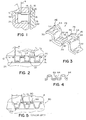
- Fig. 1 is a fragmentary, cross-sectional view of a piston and cylinder showing the oil control ring assembly in accordance with the present invention;
- Fig. 2 is a front, fragmentary, elevational view of the piston and groove including the control ring assembly;
- Fig. 3 is a fragmentary, enlarged, perspective view of the spacer-expander;
- Fig. 4 is a fragmentary, elevational view of the spacer-expander showing the abutting ends thereof; and
- Fig. 5 is a front, elevational view of a piston and groove showing a prior art spacer-expander.
- A preferred embodiment of a multi-piece oil control ring assembly in accordance with the present invention is illustrated in Figs. 1 and 2 and generally designated by the
numeral 10.Assembly 10 is shown positioned in agroove 12 of apiston 14. As shown,piston 14 is disposed within acylinder 15 of an internal combustion engine.Cylinder 15 includes acylinder wall 16. Oilcontrol ring assembly 10 includes a pair of radially split or parted rails orsegments expander 24. -
Rails Rails cylinder wall 16 by spacer-expander 24. Spacer-expander 24 axially spaces and supports therails - Spacer-expander 24, as best seen in Figs. 2, 3 and 4, is formed from an elongated steel strip into an annular ring shape. Spacer-
expander 24 includes a series of alternating, axially symmetrical corrugations orloops 28. Eachloop 28 is generally U-shaped in elevation and includeslegs bight portion 34 and a lug orrail engaging tab 36.Pad portion 34 has a stepped configuration in radial cross section, as shown in Fig. 1. The pad includes a raised, flatouter portion 42 joined tolegs portion 42. In addition,pad 34 includes a central orintermediate portion 44 which is lowered with respect toportion 42. The strip material used to form spacer-expander 24 is slit circumferentially along lines oredges Central portion 44 defines a depression or dimple generally designated 52. Each loop or corrugation further includes a lug ortab 54 joined tolegs Tab 54 defines a contact surface orline 56 which engages the radial inward face of arail Depression 52, formed during the shaping of the spacer-expander, collects enough material at the corrugation so that it may be slit atline 48 and deformed to shapelug 54 as a circumferentially elongated, generally rectangular member. The configuration of the lug results in a substantially increased circumferential contact line than has heretofore been provided. - The intermediate pad portion also provides for improved oil drainage. As shown in Fig. 3, an opening or space is provided along the slit line with the lug and below the
lug contact surface 56. - The lengthening of
contact surface 56 is also achieved through the configuration oflegs legs lug surface 56 assumes an angle "b" from vertical (Fig. 1). In the particularly preferred form, the angle is twenty degrees. However, preferably the angle falls within the range from zero to twenty degrees. - As shown in Fig. 4, the ends of spacer-
expander 24 are defined byupturned end legs End legs expander 24 eliminates excessive and, hence, reduces actual side pressure on the groove sides. The ends or points of the spacer-expander are squared during the forming process. In the alternative, the ends or points could be ground to achieve the square configuration. Further, a combination of grinding and forming could be used.Expander 24 is smaller in diameter at the points or ends than at locations ninety degrees to the points. The expander has a generally apple shape in plan. This allows the points to hug the bottom of the piston groove while assembling the rails. This is important for automated assembly. - A prior art or conventional spacer-expander is illustrated in Fig. 5 and generally designated by the numeral 80. Spacer-
expander 80 includes a series of alternating corrugations orloops 82. The loops are each defined bylegs 84, 86. The loops are generally U-shaped in elevation and include pad orbight portions 88. Thepad portions 88 of the conventional spacer-expander 80 may be stepped in cross section. The intermediate pad portion does not, however, include the dimple or depression of the present invention. In addition, each loop orcorrugation 82 defines a rounded peak, tab orlug 90. The difference in the configuration between the prior art spacer-expander and that of the subject invention is readily noted by a comparison of Figs. 2 and 5. - The Austenitic or work hardenable stainless steel from which the described spacer-expanders are formed is, of course, affected by the forming operation. When the standard cross section or prior art cross section of Fig. 5 is formed, radius corners are rendered hard in forming. The straighter sections at the pad have the material's initial hardness changed only slightly. In contrast, the dimple or depression in the top surface of the loop of the expander of the present invention produces a more even hardness.
- In the prior expander,
legs 84, 86 are angled more significantly from vertical. The lug of the prior expander has a rounded configuration and, hence, a significantly reduced contact line or surface when compared to the lugs of the subject invention. During the forming process of the spacer-expander of Figures 1 to 4, rotary tools are used. The opposed tools form the U-shaped configuration, the depressions in the central pad and the slits. The depressions provide sufficient material so that theelongated lug 54 may be formed. Insufficient material is present at the lug area in the prior art to elongate the lug. Elongation without the depression would result in thinning and possible breakage of the lug at its point of joinder to thelegs - The straightening of the legs and elongation of the contact surface results in a significant reduction in unit pressure on the
rails piston groove 12, as shown in Fig. 1. This increases the side sealing capability of the assembly. - The spacer-expander, in accordance with the present invention, may be fabricated from conventional materials such as type 201 Austenitic stainless steel or type 1070 carbon steel. A type 304 Austenitic stainless steel could be considered for more severe applications. This material is more costly, however, than the more conventional materials.
- A comparison of contact length l₁ or l₂ to pitch "p" for different size spacer-expanders incorporating the spacer-expander of Figures 1 to 4 and the prior art spacer of Fig. 5 is set forth in the following Table 1. The percent improvement over the prior ring of Fig. 5 is given. The following Table 2 provides the ratio of pitch to contact length for each size. The control length percentage or total length of the contact surface or contact length of the lugs in contact with one of the rails as a percentage of the total circumferential length of the spacer-expander is provided in Table 2. The pitch value for each groove width "w" is the same in each table.
TABLE 1 CONTACT LENGTH PER PITCH PITCH GROOVE WIDTH LUG ANGLE CONVENTIONAL INVENTION PERCENT IMPROVEMENT 0.115 2MM 0 .034 .052 53 20 .042 .057 36 0.130 2.5MM 0 .037 .051 39 20 .045 .057 26 0.160 3MM 0 .040 .062 55 20 .050 .070 40 0.220 4MM 0 .053 .093 75 20 .064 .101 57 TABLE 2 RATIO OF PITCH TO CONTACT LENGTH CONTACT LENGTH PERCENTAGE PITCH LUG ANGLE CONVENTIONAL INVENTION CONVENTIONAL INVENTION 0.115 0 3.382 2.2115 29.5% 45.0% 20 2.738 2.0175 36.5% 49.5% 0.130 0 3.513 2.5490 28.4% 39.0% 20 2.888 1.9400 34.6% 43.8% 0.160 0 4.000 2.5800 25.0% 38.0% 20 3.200 2.2850 31.2% 43.7% 0.220 0 4.150 2.3650 24.1% 42.0% 20 3.430 2.1780 29.0% 45.9% - The ratio of pitch to contact length varies within the range of approximately 2.2 to 2.6 when the angle "b" is zero degrees for a straight lug. The ratio varies within the range of approximately 1.9 to 2.3 when the angle "b" is twenty degrees for the present invention. Contact length percentage values of approximately 38 to 50 are achieved. Percent improvement of contact length per pitch values within the range of 26 to 75 percent are present for the different size spacer-expanders.
- The configuration of the spacer-expander in accordance with the present invention results in a significant increase in contact length accompanied by a significant reduction in unit pressure. The spacer substantially reduces secondary wear at the lug-to-rail interface. The end configuration or point shape, as illustrated in Fig. 4, reduces and controls localized groove side wear. Conformation quality is improved. Forming problems are not as likely to cause the spacer to appear nonsymmetrical. The formation of the dimple or depression during the forming process also tends to balance the stresses in the spacer-expander at the form tooling radii. This balancing of residual stresses increases the consistency of subsequent forming operations. This eases manufacture and improves quality. The spacer-expander and three-piece oil control ring in accordance with the present invention is more readily adapted to different piston designs. The invention overcomes problems experienced by the trend towards reduced piston height and reduced piston groove dimensions.
- In view of the above description, those of ordinary skill in the art may envision various modifications which would not depart from the inventive concepts disclosed herein. It is expressly intended, therefore, that the above description should be considered as only that of the preferred embodiment.
Claims (9)
- A spacer-expander (24) for use with a pair of rails (20, 22) in a multi-piece oil control ring assembly, the spacer-expander comprising an annular member defining a plurality of alternating corrugations (28) spaced around its periphery, each of the corrugations defining a pad (34), a pair of legs (30, 32) joined to radially extending edges of the pad, and a raised lug (54) joined to the legs and extending along the inner circumference of the member, the lug defining a rail contact surface (56), characterised in that the legs (30, 32) extend at an angle "a" from vertical within the range of 0° to 13°, the pad has a stepped configuration in cross section and includes a pair of radially spaced, circumferentially extending slits (46, 48), an opening along one of the slits at the lug and below the lug contact surface for oil drainage and a central depression (52), the lug has a generally rectangular shape in front elevation and the ratio of pitch between adjacent corrugations to the length of the contact surface (56) of each lug is less than 2.70, and the contact surface (56) of each lug extends at an angle "b" from vertical, said angle "b" being in the range of zero to twenty degrees.
- A spacer-expander according to Claim 1 wherein the ratio of pitch to the length of the contact surface is within the range of approximately 2.2 to 2.6, preferably 1.9 to 2.3.
- A spacer-expander according to Claim 1 or Claim 2 wherein the annular member terminates in opposed ends which are defined by generally vertical end legs (62, 64) positionable in abutting relationship.
- A spacer-expander according to any of Claims 1 to 3 wherein the lugs (54) define a total circumferential contact length within the range of approximately 38 percent to 50 percent of the total length of the annular member.
- An oil control ring assembly comprising a pair of radially split, generally flat annular rails (20, 22) each of which defines an inner circumferential surface, and an annular spacer-expander (10) engaging and supporting the rails in an axially spaced relationship, the expander defining alternating, axially symmetrical, generally U-shaped loops (28), each loop including a pair of legs (30, 32) joined to a pad (34), the pad having a stepped configuration in radial cross section and including a raised outer, generally flat portion (42) and an intermediate portion (44), the intermediate portion defining a dimple (52), each of the loops including an axially extending lug (54) joined to the legs, the lug defining an elongated rail contact surface (56), each of the loops including a pair of radially spaced slits (46, 48) separating the intermediate portion from the outer portion and the lug respectively, the dimple providing sufficient material during the formation of the spacer-expander so that the lug contact surface (56) may be elongated within the deformation limits of the material from which the spacer-expander is formed and so that the total length of the contact surfaces of the lugs which are in contact with one of said rails is greater than 38 percent of the total circumferential length of the spacer-expander and wherein the ratio of the pitch between adjacent loops to the length of the contact surface of each lug is less than about 2.70.
- An oil control ring assembly according to Claim 5 wherein the legs (30, 32) of the loops (28) each extend at an angle "a" from vertical of approximately zero to thirteen degrees.
- An oil control ring assembly according to Claim 5 or Claim 6 wherein the contact surface (56) of each lug extends at an angle "b" from vertical, said angle "b" being in the range of zero to twenty degrees.
- An oil control ring assembly according to any of Claims 5 to 7 wherein the ratio of the pitch between adjacent loops to the length of the contact surface of each lug is within the range of1.9 to 2.6, preferably 2.2 to 2.6 or 1.9 to 2.3.
- An oil control ring assembly according to any of Claims 5 to 8 wherein said annular member terminates in opposed ends, the ends being defined by generally vertical end legs (62, 64) positionable in abutting relationship.
Applications Claiming Priority (2)
| Application Number | Priority Date | Filing Date | Title |
|---|---|---|---|
| US794571 | 1991-11-19 | ||
| US07/794,571 US5195758A (en) | 1991-11-19 | 1991-11-19 | Three-piece oil control ring assembly |
Publications (2)
| Publication Number | Publication Date |
|---|---|
| EP0543515A1 true EP0543515A1 (en) | 1993-05-26 |
| EP0543515B1 EP0543515B1 (en) | 1996-12-18 |
Family
ID=25163028
Family Applications (1)
| Application Number | Title | Priority Date | Filing Date |
|---|---|---|---|
| EP92309841A Expired - Lifetime EP0543515B1 (en) | 1991-11-19 | 1992-10-27 | Three-piece oil control ring assembly |
Country Status (4)
| Country | Link |
|---|---|
| US (1) | US5195758A (en) |
| EP (1) | EP0543515B1 (en) |
| DE (1) | DE69216056T2 (en) |
| ES (1) | ES2094883T3 (en) |
Cited By (4)
| Publication number | Priority date | Publication date | Assignee | Title |
|---|---|---|---|---|
| CN102192322A (en) * | 2010-03-10 | 2011-09-21 | 帝国活塞环株式会社 | Combination oil ring |
| CN102292535B (en) * | 2009-01-26 | 2013-12-18 | 海德谘询有限公司 | Sealing sleeve |
| EP2778481A4 (en) * | 2011-11-11 | 2015-08-12 | Tpr Co Ltd | Combination oil ring |
| CN108779855A (en) * | 2016-03-22 | 2018-11-09 | 株式会社理研 | Combine oil-control ring |
Families Citing this family (19)
| Publication number | Priority date | Publication date | Assignee | Title |
|---|---|---|---|---|
| US5794941A (en) * | 1995-06-01 | 1998-08-18 | Dana Corporation | Piston ring assembly |
| JP4382229B2 (en) * | 2000-01-20 | 2009-12-09 | 帝国ピストンリング株式会社 | Combination oil ring |
| JP5970200B2 (en) * | 2011-04-20 | 2016-08-17 | Tpr株式会社 | Combination oil ring |
| JP5970239B2 (en) * | 2012-05-28 | 2016-08-17 | 株式会社リケン | Combination oil control ring |
| JP2014209018A (en) * | 2012-08-30 | 2014-11-06 | 日本ピストンリング株式会社 | Combination oil ring |
| JP6228452B2 (en) * | 2013-12-26 | 2017-11-08 | 株式会社リケン | Combination oil control ring |
| JP6122901B2 (en) * | 2014-07-31 | 2017-04-26 | 日本ピストンリング株式会社 | Combination oil ring |
| DE102014223989A1 (en) * | 2014-11-25 | 2016-05-25 | Federal-Mogul Burscheid Gmbh | Two-piece piston ring |
| JP5980966B2 (en) * | 2015-01-09 | 2016-08-31 | 株式会社リケン | Combination oil control ring |
| JP6530200B2 (en) * | 2015-02-23 | 2019-06-12 | 株式会社リケン | side rail |
| WO2016159269A1 (en) * | 2015-03-31 | 2016-10-06 | 日本ピストンリング株式会社 | Combined oil ring |
| JP6518493B2 (en) * | 2015-04-09 | 2019-05-22 | 株式会社リケン | Combination oil control ring |
| JP6013548B1 (en) | 2015-04-09 | 2016-10-25 | 株式会社リケン | Combination oil control ring |
| DE102017108683A1 (en) * | 2017-04-24 | 2018-10-25 | Scherdel Innotec Forschungs- Und Entwicklungs-Gmbh | Oil scraper ring spring for an oil scraper ring and oil scraper ring |
| US10626991B2 (en) * | 2017-09-29 | 2020-04-21 | Tpr Co., Ltd. | Segment, combination oil ring, and manufacturing method for a segment |
| JP6389970B1 (en) * | 2018-01-16 | 2018-09-12 | Tpr株式会社 | Combination oil ring |
| DE102018104594A1 (en) * | 2018-02-28 | 2019-08-29 | Federal-Mogul Burscheid Gmbh | Spacer spring for a three-piece oil scraper ring and three-piece oil scraper ring with this spacer spring |
| JP2020003038A (en) * | 2018-06-29 | 2020-01-09 | 株式会社リケン | Combination oil control ring |
| DE102020100764A1 (en) * | 2020-01-15 | 2021-07-15 | Federal-Mogul Burscheid Gmbh | Oil control piston ring |
Citations (3)
| Publication number | Priority date | Publication date | Assignee | Title |
|---|---|---|---|---|
| US2815996A (en) * | 1955-02-14 | 1957-12-10 | Hastings Mfg Co | Piston ring assembly |
| DE1476044A1 (en) * | 1964-12-04 | 1969-10-09 | Dana Corp | Multi-part oil wiper ring assembly |
| US3814444A (en) * | 1972-07-18 | 1974-06-04 | Hastings Mfg Co | Low friction piston ring |
Family Cites Families (17)
| Publication number | Priority date | Publication date | Assignee | Title |
|---|---|---|---|---|
| CA511623A (en) * | 1955-04-05 | F. Shirk John | Piston ring assembly | |
| US2656230A (en) * | 1951-09-10 | 1953-10-20 | Hastings Mfg Co | Piston ring assembly and elements thereof |
| US2907101A (en) * | 1954-12-30 | 1959-10-06 | Muskegon Piston Ring Co Inc | Method of producing a continuous spacer and expander for piston rings |
| US2904377A (en) * | 1957-05-21 | 1959-09-15 | Muskegon Piston Ring Co Inc | Spacer and expander for piston rings |
| CH356309A (en) * | 1957-10-02 | 1961-08-15 | Sim Sa Ets | Oil scraper ring for pistons |
| FR1267207A (en) * | 1960-06-07 | 1961-07-21 | Jacques Floquet Ets | Improvement in piston rings, especially for heat engine pistons |
| US2970022A (en) * | 1960-07-05 | 1961-01-31 | Hastings Mfg Co | Piston ring assemblies and elements thereof |
| US3346264A (en) * | 1965-01-18 | 1967-10-10 | Muskegon Piston Ring Co Inc | Oil rings |
| US3442519A (en) * | 1967-09-20 | 1969-05-06 | Muskegon Piston Ring Co | Monorail piston ring |
| JPS4815801B1 (en) * | 1969-07-12 | 1973-05-17 | ||
| US4130288A (en) * | 1977-04-20 | 1978-12-19 | Questor Corporation | Piston ring |
| US4194747A (en) * | 1978-12-05 | 1980-03-25 | Muskegon Piston Ring Company | Three-piece oil control ring |
| US4226430A (en) * | 1978-12-05 | 1980-10-07 | Muskegon Piston Ring Company | Two-piece oil control ring |
| US4585237A (en) * | 1979-01-15 | 1986-04-29 | Hastings Manufacturing Company | Piston and oil control ring therefor |
| US4429885A (en) * | 1982-11-04 | 1984-02-07 | Kabushiki Kaisha Riken | Spacer and expander member for holding and biasing piston ring rails |
| JPH063265B2 (en) * | 1987-12-17 | 1994-01-12 | 日本ピストンリング株式会社 | Combination oil ring |
| CA2023718C (en) * | 1989-08-31 | 1998-07-14 | Sumio Ono | Steel oil ring assembly |
-
1991
- 1991-11-19 US US07/794,571 patent/US5195758A/en not_active Expired - Lifetime
-
1992
- 1992-10-27 EP EP92309841A patent/EP0543515B1/en not_active Expired - Lifetime
- 1992-10-27 DE DE69216056T patent/DE69216056T2/en not_active Expired - Lifetime
- 1992-10-27 ES ES92309841T patent/ES2094883T3/en not_active Expired - Lifetime
Patent Citations (3)
| Publication number | Priority date | Publication date | Assignee | Title |
|---|---|---|---|---|
| US2815996A (en) * | 1955-02-14 | 1957-12-10 | Hastings Mfg Co | Piston ring assembly |
| DE1476044A1 (en) * | 1964-12-04 | 1969-10-09 | Dana Corp | Multi-part oil wiper ring assembly |
| US3814444A (en) * | 1972-07-18 | 1974-06-04 | Hastings Mfg Co | Low friction piston ring |
Cited By (10)
| Publication number | Priority date | Publication date | Assignee | Title |
|---|---|---|---|---|
| CN102292535B (en) * | 2009-01-26 | 2013-12-18 | 海德谘询有限公司 | Sealing sleeve |
| CN102192322A (en) * | 2010-03-10 | 2011-09-21 | 帝国活塞环株式会社 | Combination oil ring |
| CN102192322B (en) * | 2010-03-10 | 2016-02-17 | 帝伯爱尔株式会社 | Combined oil ring |
| EP2778481A4 (en) * | 2011-11-11 | 2015-08-12 | Tpr Co Ltd | Combination oil ring |
| US9726286B2 (en) | 2011-11-11 | 2017-08-08 | Tpr Co., Ltd | Combination oil ring |
| EP3205908A1 (en) * | 2011-11-11 | 2017-08-16 | TPR Co., Ltd. | Combination oil ring |
| US9845873B2 (en) | 2011-11-11 | 2017-12-19 | Tpr Co., Ltd. | Combination oil ring |
| US10072755B2 (en) | 2011-11-11 | 2018-09-11 | Tpr Co., Ltd. | Combination oil ring |
| EP3392532A1 (en) * | 2011-11-11 | 2018-10-24 | TPR Co., Ltd. | Combination oil ring |
| CN108779855A (en) * | 2016-03-22 | 2018-11-09 | 株式会社理研 | Combine oil-control ring |
Also Published As
| Publication number | Publication date |
|---|---|
| DE69216056T2 (en) | 1997-06-12 |
| US5195758A (en) | 1993-03-23 |
| DE69216056D1 (en) | 1997-01-30 |
| ES2094883T3 (en) | 1997-02-01 |
| EP0543515B1 (en) | 1996-12-18 |
Similar Documents
| Publication | Publication Date | Title |
|---|---|---|
| EP0543515A1 (en) | Three-piece oil control ring assembly | |
| US7243596B2 (en) | Spacer expander | |
| EP1377766B1 (en) | Side rail and combined oil control ring incorporated with the side rails for reduction of oil consumption | |
| EP2578908A1 (en) | Oil ring for internal combustion engine | |
| US4429885A (en) | Spacer and expander member for holding and biasing piston ring rails | |
| US4099730A (en) | Piston ring construction | |
| EP1596106B1 (en) | Combination oil control ring | |
| US3477732A (en) | Spacer-expander | |
| US4759266A (en) | Multiple part oil-control ring for piston | |
| US5165367A (en) | Cylinder liners | |
| US4346646A (en) | Piston for internal combustion engines | |
| US4079949A (en) | Integral spring piston ring | |
| US4145060A (en) | Axially and radially clamping spreader ring for an oil scraping piston ring | |
| US4462602A (en) | Piston ring with annular expander spring | |
| JP4104774B2 (en) | 2-piece combination oil ring | |
| US3346252A (en) | Narrow width piston ring and expander-spacer | |
| US2236721A (en) | Piston ring | |
| US4542907A (en) | Corrugated expander for piston ring assembly | |
| US2346897A (en) | Multipiece piston ring | |
| US4130288A (en) | Piston ring | |
| US4226430A (en) | Two-piece oil control ring | |
| US5042825A (en) | Combined oil ring assembly | |
| JPH022512B2 (en) | ||
| JPH0587366U (en) | 2-piece oil ring | |
| JPS6326463A (en) | Combined oil ring |
Legal Events
| Date | Code | Title | Description |
|---|---|---|---|
| PUAI | Public reference made under article 153(3) epc to a published international application that has entered the european phase |
Free format text: ORIGINAL CODE: 0009012 |
|
| AK | Designated contracting states |
Kind code of ref document: A1 Designated state(s): DE ES FR GB IT |
|
| 17P | Request for examination filed |
Effective date: 19931104 |
|
| 17Q | First examination report despatched |
Effective date: 19950614 |
|
| GRAG | Despatch of communication of intention to grant |
Free format text: ORIGINAL CODE: EPIDOS AGRA |
|
| GRAH | Despatch of communication of intention to grant a patent |
Free format text: ORIGINAL CODE: EPIDOS IGRA |
|
| GRAH | Despatch of communication of intention to grant a patent |
Free format text: ORIGINAL CODE: EPIDOS IGRA |
|
| ITF | It: translation for a ep patent filed |
Owner name: BARZANO' E ZANARDO ROMA S.P.A. |
|
| GRAA | (expected) grant |
Free format text: ORIGINAL CODE: 0009210 |
|
| AK | Designated contracting states |
Kind code of ref document: B1 Designated state(s): DE ES FR GB IT |
|
| REF | Corresponds to: |
Ref document number: 69216056 Country of ref document: DE Date of ref document: 19970130 |
|
| REG | Reference to a national code |
Ref country code: ES Ref legal event code: FG2A Ref document number: 2094883 Country of ref document: ES Kind code of ref document: T3 |
|
| ET | Fr: translation filed | ||
| PLBE | No opposition filed within time limit |
Free format text: ORIGINAL CODE: 0009261 |
|
| STAA | Information on the status of an ep patent application or granted ep patent |
Free format text: STATUS: NO OPPOSITION FILED WITHIN TIME LIMIT |
|
| 26N | No opposition filed | ||
| REG | Reference to a national code |
Ref country code: GB Ref legal event code: IF02 |
|
| PGFP | Annual fee paid to national office [announced via postgrant information from national office to epo] |
Ref country code: DE Payment date: 20101029 Year of fee payment: 19 |
|
| PGFP | Annual fee paid to national office [announced via postgrant information from national office to epo] |
Ref country code: IT Payment date: 20101016 Year of fee payment: 19 |
|
| PGFP | Annual fee paid to national office [announced via postgrant information from national office to epo] |
Ref country code: GB Payment date: 20110930 Year of fee payment: 20 Ref country code: FR Payment date: 20111005 Year of fee payment: 20 |
|
| PGFP | Annual fee paid to national office [announced via postgrant information from national office to epo] |
Ref country code: ES Payment date: 20111026 Year of fee payment: 20 |
|
| REG | Reference to a national code |
Ref country code: DE Ref legal event code: R071 Ref document number: 69216056 Country of ref document: DE |
|
| REG | Reference to a national code |
Ref country code: DE Ref legal event code: R071 Ref document number: 69216056 Country of ref document: DE |
|
| REG | Reference to a national code |
Ref country code: GB Ref legal event code: PE20 Expiry date: 20121026 |
|
| PG25 | Lapsed in a contracting state [announced via postgrant information from national office to epo] |
Ref country code: GB Free format text: LAPSE BECAUSE OF EXPIRATION OF PROTECTION Effective date: 20121026 |
|
| REG | Reference to a national code |
Ref country code: ES Ref legal event code: FD2A Effective date: 20130711 |
|
| PG25 | Lapsed in a contracting state [announced via postgrant information from national office to epo] |
Ref country code: ES Free format text: LAPSE BECAUSE OF EXPIRATION OF PROTECTION Effective date: 20121028 |