EP0543146B1 - Pied de maintien pour porte-bagages de toit d'un véhicule automobile - Google Patents
Pied de maintien pour porte-bagages de toit d'un véhicule automobile Download PDFInfo
- Publication number
- EP0543146B1 EP0543146B1 EP92117596A EP92117596A EP0543146B1 EP 0543146 B1 EP0543146 B1 EP 0543146B1 EP 92117596 A EP92117596 A EP 92117596A EP 92117596 A EP92117596 A EP 92117596A EP 0543146 B1 EP0543146 B1 EP 0543146B1
- Authority
- EP
- European Patent Office
- Prior art keywords
- roof
- bearing
- pedestal
- clamping
- curvature
- Prior art date
- Legal status (The legal status is an assumption and is not a legal conclusion. Google has not performed a legal analysis and makes no representation as to the accuracy of the status listed.)
- Expired - Lifetime
Links
Images
Classifications
-
- B—PERFORMING OPERATIONS; TRANSPORTING
- B60—VEHICLES IN GENERAL
- B60R—VEHICLES, VEHICLE FITTINGS, OR VEHICLE PARTS, NOT OTHERWISE PROVIDED FOR
- B60R9/00—Supplementary fittings on vehicle exterior for carrying loads, e.g. luggage, sports gear or the like
- B60R9/04—Carriers associated with vehicle roof
- B60R9/058—Carriers associated with vehicle roof characterised by releasable attaching means between carrier and roof
Definitions
- the invention relates to a support foot for a roof rack of a motor vehicle according to the preamble of claim 1.
- a known roof rack (DE 35 32 170 A1) with a generic support foot
- two support feet are each connected by a cross member and the support feet are each designed such that they can be placed on an associated, lateral roof area with a support plate and held with the aid of a fastening device on the roof edge area are.
- the fastening device comprises a clamping bracket and a clamping screw.
- the tensioning clamp is arranged on the side of the support foot and projects downwards over the contact plate of the support foot with a contact part that is bent obliquely towards the center of the roof rack for lateral support and reaching under the roof edge area.
- the tensioning clip rests with an upper support part or its contact edge in a contact line on a support surface of the support foot.
- the clamp also points in a middle section a hole through which the clamping screw engages from the outside in a clamping screw thread in the support leg.
- the area around the bore is concavely spherical as a spherical screw head system, with an excess of the bore diameter compared to the screw bolt diameter, so that the tension clamp is pivotally held on the spherical screw head system.
- the spherical contact of the screw head itself is achieved in a manner known per se via a washer with a spherical contact surface.
- the system parts of the clamps as short, level webs should lie flat on the roof edge area for favorable support and good power transmission, since only punctiform or systems lead to a shaky fastening of the roof rack and to mechanical overloading with the risk of damage at the system locations.
- a lower part of the support leg is screwed tightly to the upper part of the B-pillar.
- the upper support foot part is connected with a spherical contact surface to compensate for longitudinal tolerances.
- the object of the invention is to develop a generic support foot for a roof rack of a motor vehicle in such a way that its fastening device automatically adjusts itself for a flat contact with a longitudinally curved roof edge region of a motor vehicle.
- the bearing edge of the support part has a convex curvature whose direction extends towards the center of the vehicle.
- the support surface for the contact edge is formed with a concave curvature corresponding to the curvature of the contact edge.
- the advantage here is that when the tensioning screw is tightened, the longitudinal adjustment and positioning of the tensioning clamp is carried out automatically by pivoting between the contact edge and the support surface, essentially while maintaining the linear contact along the curvature.
- This setting is obtained in the case of an advantageously flat longitudinal contact of the contact part of the tensioning clamp on a roof edge area which deviates somewhat from the longitudinal direction of the vehicle as a result of a curvature.
- the radius of curvature of such a roof edge curvature is so large that it is negligibly small in the short longitudinal region of the plant part, which usually comprises a flexible support, or is accommodated in the flexible support.
- This setting thus results in a flat support of the plant part with a fixed mounting of the support foot and a favorable power transmission, in which punctiform supports with the risk of mechanical damage are avoided.
- the arrangement according to the invention is simple and inexpensive to manufacture and assemble.
- the curvature according to claim 2 is circular in a plane that extends parallel to the screw axis and in the vehicle longitudinal direction.
- the center point for the radius of such a circular curvature lies at the point of a vertical projection of the center point of the spherical screw head system onto the aforementioned plane.
- the support surface is thus approximately cylindrical over its extension transversely to the contact edge, since when the clamping screw is tightened and depending on the circumstances in the vehicle transverse direction, the contact edge on the support surface must be designed to be slidable while maintaining the circular system in order to be able to carry out the transverse adjustment.
- the axis of the clamping screw and the contact plate are at an angle of 5 ° to 15 ° with respect to the cross beam direction or with respect to a horizontal plane and the support surface is around an angle of 50 ° to 70 ° inclined upwards.
- a correspondingly favorable geometry for the tension clamp results if the middle part, as a substantially flat, flat component in the functional position, is inclined upwards at an angle of 50 ° to 70 ° relative to the cross beam direction or the horizontal plane.
- the spherical screw head system is formed in a central area, wherein a bead can be provided in particular for reinforcement around the spherical area.
- the upper support part as a substantially flat, flat component is inclined at an angle of 5 ° to 15 ° upwards relative to this plane and the lower contact part as an essentially flat, flat bar at an angle of 15 ° to 60 ° inclined down.
- the angular position of the lower part of the system essentially depends on the conditions on the respective vehicle.
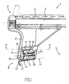
- a section through a roof rack 1 in the side region of a support leg 2 is shown. This is connected via a cross bar 3 to an opposite support leg 2 (not shown).
- the cross member 3 is designed as a supporting part for roof loads, 4 holders, for example ski holders, bicycle holders, etc., being insertable in a U-shaped longitudinal groove.
- a lock 5 is attached to the end face of the cross member 3, with which access to the longitudinal groove 4 and also access to a tensioning screw 7 can be blocked off via a cover 6.
- the clamping screw 7 is part of a fastening device 8, which further comprises a clamping clip 9.
- the support foot 2 can be placed on a lateral roof area 11 (shown in broken lines) with a contact plate 10.
- the tensioning clamp 9 is arranged on the side of the support leg and, under the side, engages under a roof edge region 13 with a bent contact part 12.
- the tensioning clamp 9 further lies with an upper support part 14 or its contact edge 15 on an obliquely upwardly extending support surface 16 of the support foot 2.
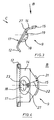
- the tensioning clamp 9 contains a bore 19 within a spherical screw head system 18. The bore diameter is larger than the diameter of the screw bolt of the tensioning screw 7. This engages in a thread 20 on the support leg 2.
- the contact edge 15 of the support part 14 has a convex, circular curvature 21, the support part 14 being a flat, flat component at an angle of approximately 5 ° to the horizontal plane is inclined upwards in the functional position (Fig. 1).
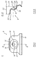
- the radius 22 for this circular curvature 21 has its center 23 in a vertical projection 24 of the center 25 for the radius 26 of the spherical screw head system 18 on a plane which extends parallel to the clamping screw axis and in the vehicle longitudinal direction.
- the support part with the flat, circular curvature lies in this plane (see in particular FIG. 6).
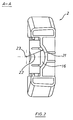
- a corresponding circular curvature 21, but here in a concave shape, starting from the center 23 with the radius 22 is provided on the support surface 16 (see FIG. 2).
- This support surface 16 is therefore part of a cylindrical surface due to its oblique upward extension.
- the spherical screw head system 18 is surrounded by a molded-in bead 27.
- the fastening device 8 shown has the following function: Before fastening the support foot 2, the tensioning screw 7 is loosened and the support foot 2 with the contact plate 10 is placed on the lateral roof area 11, the tensioning clip with its contact part 12 still being at a distance from the roof edge area 13. The clamp 9 is now brought with the contact part 12 to the roof edge area 13 until it lies flat there, as shown in Fig. 1. As a result of this approach, the height of the contact edge 15 of the support part 14 on the obliquely upwardly extending support surface 16 has been adjusted, with a corresponding pivoting in the spherical screw head system 18 having taken place.
- the clamping clip 9 has been adjusted in the vehicle longitudinal direction in accordance with the longitudinal course of the roof bearing area 13 by pivoting on the circular curvature 21, in such a way that the bearing part 12 lies flat against the roof edge area 13 with its entire longitudinal extent, just like the bearing edge 15 with a continuous one Contact line, that is not only supported point by point on the support surface 16. This is essentially achieved by the described assignment of the center points 23 and 25 for the radii 22 and 26.
- the subject of the application provides a support leg 2 which, with a simple design, enables suitable adjustment and adaptation to curved longitudinal profiles of roof edge regions 13.
Landscapes
- Engineering & Computer Science (AREA)
- Mechanical Engineering (AREA)
- Fittings On The Vehicle Exterior For Carrying Loads, And Devices For Holding Or Mounting Articles (AREA)
- Body Structure For Vehicles (AREA)
- Vehicle Step Arrangements And Article Storage (AREA)
Claims (4)
- Pied pour un porte-bagages de toit pour véhicule automobile, dans lequel
deux pieds (2) sont reliés par une traverse (3) et peuvent être posés sur la zone latérale du toit (11) par l'intermédiaire d'une plaque d'appui (10) et maintenus à l'aide d'un dispositif de fixation (8) dans la zone du bord du toit (13),
le dispositif de fixation (8) comprenant une bride de serrage (9) qui a, dans le sens longitudinal du véhicule, une dimension préalablement définie comme étant la longueur de la bride, et une vis de serrage (7),
la bride de serrage (9) étant disposée latéralement par rapport au pied (2) et dépassant vers le bas la plaque d'appui (10) du pied (2) par une partie d'appui inférieure (12) repliée vers le milieu du porte-bagages pour assurer un appui latéral et un accrochage au-dessous de la zone du bord du toit (13),
la bride de serrage (9) s'appliquant, par une partie d'appui supérieure (14) ou par le bord d'appui (15) de celle-ci, sur une surface d'appui (16) du pied (2) le long d'une ligne de contact, et
la bride de serrage (9) présentant, dans sa partie centrale (17), un trou (19) à travers lequel la vis de serrage (7) est vissée, de l'extérieur latéralement, dans un taraudage (20) prévu dans le pied (2), et la bride de serrage (9) pouvant être pressée, lors du serrage de la vis de serrage (7), à la fois par sa partie d'appui (12) contre la zone du bord du toit (13) et par sa partie d'appui (14) contre la surface d'appui (16), la région qui borde le trou (19) étant réalisée sous une forme sphérique concave pour servir de siège sphérique (18) pour la tête de la vis, avec un diamètre du trou légèrement supérieur au diamètre de la tige de la vis, et la surface d'appui (16) étant réalisée en forme de surface de glissement oblique vers le haut et le milieu pour le bord d'appui (15) de la partie d'appui (14),
caractérisé en ce que le bord d'appui (15) de la partie d'appui (14) présente une courbure convexe (21) dirigée vers le milieu du véhicule, et
en ce que la surface d'appui (16) pour le bord d'appui (15) présente une courbure concave (21) de forme correspondante à celle de la courbure du bord d'appui (15), de sorte qu'il se produise, lors d'une application longitudinale, surface contre surface, de la partie d'appui (12) contre une zone du bord du toit (13) qui s'écarte de la direction longitudinale du véhicule par une courbure longitudinale, et lors du serrage de la vis de serrage (7), un positionnement longitudinal automatique de la bride de serrage (9) par pivotement entre le bord d'appui (15) et la surface d'appui (16), le contact linéaire le long de la courbure (21) étant essentiellement maintenu. - Pied selon la revendication 1, caractérosé en ce que la courbure (21) est de forme circulaire dans un plan qui s'étend parallèlement a la vis de serrage (7) et dans la direction longitudinale du véhicule, avec un rayon (22) a partir d'un centre (23) qui correspond à la projection verticale (24) du centre (25) du siège sphérique (18) de la tête de vis sur ledit plan.
- Pied selon la revendication 1 ou 2, caractérisé en ce que l'axe de la vis de serrage (7) et la plaque d'appui (10) sont inclinés vers le haut par rapport à la direction de la traverse ou par rapport à un plan horizontal avec un angle compris entre 5° et 15°, et la surface d'appui (16) est inclinée vers le haut avec un angle de 50° à 70°.
- Pied selon l'une quelconque des revendications 1 à 3, caractérisé en ce que la partie centrale (17) de la bride de serrage (9), en tant qu'élément essentiellement plat et plan, présente, en position de travail, une inclinaison vers le haut d'un angle compris entre 50° et 70° par rapport à la direction de la traverse ou par rapport au plan horizontal, et le siège sphérique (18) de la tête de vis est formé dans une zone centrale, et
en ce que la partie d'appui supérieure (14), en tant qu'élément essentiellement plat et plan, présente une inclinaison vers le haut d'un angle compris entre 5° et 15° par rapport à ce plan, et la partie d'appui inférieure (12), en tant que rebord essentiellement plat et plan, présente une inclinaison vers le bas d'un angle compris entre 15° et 60°.
Applications Claiming Priority (2)
| Application Number | Priority Date | Filing Date | Title |
|---|---|---|---|
| DE4138235 | 1991-11-21 | ||
| DE4138235A DE4138235C1 (fr) | 1991-11-21 | 1991-11-21 |
Publications (2)
| Publication Number | Publication Date |
|---|---|
| EP0543146A1 EP0543146A1 (fr) | 1993-05-26 |
| EP0543146B1 true EP0543146B1 (fr) | 1995-08-09 |
Family
ID=6445242
Family Applications (1)
| Application Number | Title | Priority Date | Filing Date |
|---|---|---|---|
| EP92117596A Expired - Lifetime EP0543146B1 (fr) | 1991-11-21 | 1992-10-15 | Pied de maintien pour porte-bagages de toit d'un véhicule automobile |
Country Status (6)
| Country | Link |
|---|---|
| EP (1) | EP0543146B1 (fr) |
| AT (1) | ATE126145T1 (fr) |
| CZ (1) | CZ281160B6 (fr) |
| DE (2) | DE4138235C1 (fr) |
| DK (1) | DK0543146T3 (fr) |
| ES (1) | ES2077952T3 (fr) |
Families Citing this family (2)
| Publication number | Priority date | Publication date | Assignee | Title |
|---|---|---|---|---|
| JPH08192691A (ja) * | 1995-01-20 | 1996-07-30 | Kaameito:Kk | 車輛用荷台の固定装置 |
| DE102014208683B4 (de) * | 2014-02-18 | 2018-02-15 | Atera Gmbh | Dachträgeranordnung für ein Kraftfahrzeug |
Family Cites Families (8)
| Publication number | Priority date | Publication date | Assignee | Title |
|---|---|---|---|---|
| FR1366601A (fr) * | 1962-08-31 | 1964-07-10 | O M P Ohg Ponti & C | Patte articulée pour fixer et supporter une galerie porte-bagages sur le toit d'un véhicule automobile |
| US3722765A (en) * | 1971-11-19 | 1973-03-27 | Beatrice Foods Co | Car top rack |
| DE3138146A1 (de) * | 1981-09-25 | 1983-04-07 | Klaus Dipl.-Ing. 8900 Augsburg Hartmann | Stuetzfuss fuer dachtraeger von personenkraftwagen, winkelverstellbar |
| DE3243878C2 (de) * | 1982-11-26 | 1986-10-23 | Eberhard 7981 Grünkraut Tittel | Gegen Diebstahl gesicherter Auto-Dachträger |
| DE3406431A1 (de) * | 1984-02-22 | 1985-09-05 | Heinrich Wunder GmbH & Co KG, 8060 Dachau | Dachlastentraeger fuer kraftfahrzeuge |
| US4688706A (en) * | 1985-09-05 | 1987-08-25 | Industri Ab Thule | Device for carrying a load |
| DE3533749A1 (de) * | 1985-09-21 | 1987-04-16 | Ford Werke Ag | Dachgepaecktraegerbefestigung an kraftfahrzeugkarosserien |
| DE4041309C2 (de) * | 1990-12-21 | 1995-07-20 | Eberhard Tittel | Lastenträger |
-
1991
- 1991-11-21 DE DE4138235A patent/DE4138235C1/de not_active Expired - Fee Related
-
1992
- 1992-10-15 DK DK92117596.4T patent/DK0543146T3/da active
- 1992-10-15 DE DE59203220T patent/DE59203220D1/de not_active Expired - Fee Related
- 1992-10-15 ES ES92117596T patent/ES2077952T3/es not_active Expired - Lifetime
- 1992-10-15 AT AT92117596T patent/ATE126145T1/de not_active IP Right Cessation
- 1992-10-15 EP EP92117596A patent/EP0543146B1/fr not_active Expired - Lifetime
- 1992-11-02 CZ CS923293A patent/CZ281160B6/cs not_active IP Right Cessation
Also Published As
| Publication number | Publication date |
|---|---|
| DE4138235C1 (fr) | 1993-05-19 |
| DK0543146T3 (da) | 1995-11-27 |
| CZ281160B6 (cs) | 1996-07-17 |
| ES2077952T3 (es) | 1995-12-01 |
| CZ329392A3 (en) | 1993-06-16 |
| EP0543146A1 (fr) | 1993-05-26 |
| DE59203220D1 (de) | 1995-09-14 |
| ATE126145T1 (de) | 1995-08-15 |
Similar Documents
| Publication | Publication Date | Title |
|---|---|---|
| EP0503305B1 (fr) | Galerie de toit pour véhicules avec rails de toit | |
| DE3801103C2 (de) | Befestigungsvorrichtung für einstellbare Frontblenden von Schubladen | |
| EP1040962A2 (fr) | Rétroviseur intérieur pour véhicules, en particulier véhicules à moteur | |
| EP1977957B1 (fr) | Face Avant et procédé de montage | |
| DE19542109C2 (de) | Befestigungsanordnung einer Reling auf einem Fahrzeugdach | |
| EP0803391A1 (fr) | Toit pliant pour véhicule | |
| DE3637856A1 (de) | Abdeckleiste fuer dachkanaele von kraftwagen | |
| EP0852190B1 (fr) | Pièce de liaison | |
| EP0459187B1 (fr) | Phare pour véhicule | |
| EP0543146B1 (fr) | Pied de maintien pour porte-bagages de toit d'un véhicule automobile | |
| EP0585684A1 (fr) | Dispositif pour fixation des guides pour ascenseurs | |
| EP0211253A1 (fr) | Assemblage de support élastique pour radiateurs de moteurs à combustion interne, notamment dans des véhicules à moteur | |
| EP0960760B1 (fr) | Dispositif de fixation pour une fenêtre de véhicule à moteur | |
| EP0978416B1 (fr) | Dispositif pour la fixation réglable d'un phare | |
| DE19509754C1 (de) | Halterungsvorrichtung für Dachkoffer | |
| EP0086329B1 (fr) | Dispositif d'assemblage | |
| DE19533467C2 (de) | Halterung für Räder oder dgl. an Fahrzeugen | |
| EP0904980B1 (fr) | Dispositif de fixation d'un feux clignotant | |
| EP1366942B1 (fr) | Fixation de capote pour véhicule convertible | |
| EP0682766B1 (fr) | Element chauffant a plusieurs sections avec systemes de fixation | |
| DE10332507B4 (de) | Vorrichtung zur Befestigung eines elastischen Aggregatelagers, insbesondere Motorgetriebelagers in einem Kraftfahrzeug | |
| EP0817305A2 (fr) | Support à collier pour la fixation d'un corps allongé à un mur | |
| WO1987004982A1 (fr) | Fixation pour galerie porte-bagages | |
| EP0778170B1 (fr) | Dispositif pour la fixation avec réglage d'un componant, en particulier pour capote pliante de véhicule | |
| DE3625785A1 (de) | Auto-dachtraeger fuer ein autodach ohne regenrinne |
Legal Events
| Date | Code | Title | Description |
|---|---|---|---|
| PUAI | Public reference made under article 153(3) epc to a published international application that has entered the european phase |
Free format text: ORIGINAL CODE: 0009012 |
|
| AK | Designated contracting states |
Kind code of ref document: A1 Designated state(s): AT BE CH DE DK ES FR GB GR IE IT LI LU NL PT SE |
|
| ITCL | It: translation for ep claims filed |
Representative=s name: ING. C. GREGORJ S.P.A. |
|
| 17P | Request for examination filed |
Effective date: 19930616 |
|
| GBC | Gb: translation of claims filed (gb section 78(7)/1977) | ||
| 17Q | First examination report despatched |
Effective date: 19940629 |
|
| EL | Fr: translation of claims filed | ||
| GRAA | (expected) grant |
Free format text: ORIGINAL CODE: 0009210 |
|
| AK | Designated contracting states |
Kind code of ref document: B1 Designated state(s): AT BE CH DE DK ES FR GB GR IE IT LI LU NL PT SE |
|
| PG25 | Lapsed in a contracting state [announced via postgrant information from national office to epo] |
Ref country code: GR Free format text: LAPSE BECAUSE OF FAILURE TO SUBMIT A TRANSLATION OF THE DESCRIPTION OR TO PAY THE FEE WITHIN THE PRESCRIBED TIME-LIMIT Effective date: 19950809 |
|
| REF | Corresponds to: |
Ref document number: 126145 Country of ref document: AT Date of ref document: 19950815 Kind code of ref document: T |
|
| REG | Reference to a national code |
Ref country code: IE Ref legal event code: FG4D Free format text: 64802 |
|
| REF | Corresponds to: |
Ref document number: 59203220 Country of ref document: DE Date of ref document: 19950914 |
|
| ITF | It: translation for a ep patent filed |
Owner name: ING. C. GREGORJ S.P.A. |
|
| ET | Fr: translation filed | ||
| PG25 | Lapsed in a contracting state [announced via postgrant information from national office to epo] |
Ref country code: PT Effective date: 19951109 |
|
| REG | Reference to a national code |
Ref country code: DK Ref legal event code: T3 |
|
| REG | Reference to a national code |
Ref country code: ES Ref legal event code: FG2A Ref document number: 2077952 Country of ref document: ES Kind code of ref document: T3 |
|
| GBT | Gb: translation of ep patent filed (gb section 77(6)(a)/1977) |
Effective date: 19951113 |
|
| PLBE | No opposition filed within time limit |
Free format text: ORIGINAL CODE: 0009261 |
|
| STAA | Information on the status of an ep patent application or granted ep patent |
Free format text: STATUS: NO OPPOSITION FILED WITHIN TIME LIMIT |
|
| 26N | No opposition filed | ||
| PGFP | Annual fee paid to national office [announced via postgrant information from national office to epo] |
Ref country code: SE Payment date: 19990907 Year of fee payment: 8 |
|
| PGFP | Annual fee paid to national office [announced via postgrant information from national office to epo] |
Ref country code: LU Payment date: 19990922 Year of fee payment: 8 |
|
| PGFP | Annual fee paid to national office [announced via postgrant information from national office to epo] |
Ref country code: ES Payment date: 19991001 Year of fee payment: 8 |
|
| PGFP | Annual fee paid to national office [announced via postgrant information from national office to epo] |
Ref country code: GB Payment date: 19991013 Year of fee payment: 8 |
|
| PGFP | Annual fee paid to national office [announced via postgrant information from national office to epo] |
Ref country code: BE Payment date: 19991020 Year of fee payment: 8 |
|
| PGFP | Annual fee paid to national office [announced via postgrant information from national office to epo] |
Ref country code: IE Payment date: 19991021 Year of fee payment: 8 |
|
| PGFP | Annual fee paid to national office [announced via postgrant information from national office to epo] |
Ref country code: DK Payment date: 19991028 Year of fee payment: 8 Ref country code: FR Payment date: 19991028 Year of fee payment: 8 |
|
| PGFP | Annual fee paid to national office [announced via postgrant information from national office to epo] |
Ref country code: AT Payment date: 19991029 Year of fee payment: 8 Ref country code: NL Payment date: 19991029 Year of fee payment: 8 |
|
| PGFP | Annual fee paid to national office [announced via postgrant information from national office to epo] |
Ref country code: DE Payment date: 19991104 Year of fee payment: 8 |
|
| PGFP | Annual fee paid to national office [announced via postgrant information from national office to epo] |
Ref country code: CH Payment date: 20000113 Year of fee payment: 8 |
|
| PG25 | Lapsed in a contracting state [announced via postgrant information from national office to epo] |
Ref country code: IE Free format text: LAPSE BECAUSE OF NON-PAYMENT OF DUE FEES Effective date: 20001015 Ref country code: AT Free format text: LAPSE BECAUSE OF NON-PAYMENT OF DUE FEES Effective date: 20001015 Ref country code: LU Free format text: LAPSE BECAUSE OF NON-PAYMENT OF DUE FEES Effective date: 20001015 Ref country code: DK Free format text: LAPSE BECAUSE OF NON-PAYMENT OF DUE FEES Effective date: 20001015 Ref country code: GB Free format text: LAPSE BECAUSE OF NON-PAYMENT OF DUE FEES Effective date: 20001015 |
|
| PG25 | Lapsed in a contracting state [announced via postgrant information from national office to epo] |
Ref country code: ES Free format text: LAPSE BECAUSE OF NON-PAYMENT OF DUE FEES Effective date: 20001016 |
|
| PG25 | Lapsed in a contracting state [announced via postgrant information from national office to epo] |
Ref country code: SE Free format text: THE PATENT HAS BEEN ANNULLED BY A DECISION OF A NATIONAL AUTHORITY Effective date: 20001030 |
|
| PG25 | Lapsed in a contracting state [announced via postgrant information from national office to epo] |
Ref country code: BE Free format text: LAPSE BECAUSE OF NON-PAYMENT OF DUE FEES Effective date: 20001031 Ref country code: LI Free format text: LAPSE BECAUSE OF NON-PAYMENT OF DUE FEES Effective date: 20001031 Ref country code: CH Free format text: LAPSE BECAUSE OF NON-PAYMENT OF DUE FEES Effective date: 20001031 |
|
| BERE | Be: lapsed |
Owner name: VOTEX G.M.B.H. Effective date: 20001031 |
|
| PG25 | Lapsed in a contracting state [announced via postgrant information from national office to epo] |
Ref country code: NL Free format text: LAPSE BECAUSE OF NON-PAYMENT OF DUE FEES Effective date: 20010501 |
|
| REG | Reference to a national code |
Ref country code: DK Ref legal event code: EBP |
|
| GBPC | Gb: european patent ceased through non-payment of renewal fee |
Effective date: 20001015 |
|
| REG | Reference to a national code |
Ref country code: CH Ref legal event code: PL |
|
| EUG | Se: european patent has lapsed |
Ref document number: 92117596.4 |
|
| PG25 | Lapsed in a contracting state [announced via postgrant information from national office to epo] |
Ref country code: FR Free format text: LAPSE BECAUSE OF NON-PAYMENT OF DUE FEES Effective date: 20010629 |
|
| NLV4 | Nl: lapsed or anulled due to non-payment of the annual fee |
Effective date: 20010501 |
|
| PG25 | Lapsed in a contracting state [announced via postgrant information from national office to epo] |
Ref country code: DE Free format text: LAPSE BECAUSE OF NON-PAYMENT OF DUE FEES Effective date: 20010703 |
|
| REG | Reference to a national code |
Ref country code: FR Ref legal event code: ST |
|
| REG | Reference to a national code |
Ref country code: IE Ref legal event code: MM4A |
|
| REG | Reference to a national code |
Ref country code: ES Ref legal event code: FD2A Effective date: 20011113 |
|
| PG25 | Lapsed in a contracting state [announced via postgrant information from national office to epo] |
Ref country code: IT Free format text: LAPSE BECAUSE OF NON-PAYMENT OF DUE FEES;WARNING: LAPSES OF ITALIAN PATENTS WITH EFFECTIVE DATE BEFORE 2007 MAY HAVE OCCURRED AT ANY TIME BEFORE 2007. THE CORRECT EFFECTIVE DATE MAY BE DIFFERENT FROM THE ONE RECORDED. Effective date: 20051015 |