EP0542809B1 - Apparatus and method for curtain coating - Google Patents
Apparatus and method for curtain coating Download PDFInfo
- Publication number
- EP0542809B1 EP0542809B1 EP91914065A EP91914065A EP0542809B1 EP 0542809 B1 EP0542809 B1 EP 0542809B1 EP 91914065 A EP91914065 A EP 91914065A EP 91914065 A EP91914065 A EP 91914065A EP 0542809 B1 EP0542809 B1 EP 0542809B1
- Authority
- EP
- European Patent Office
- Prior art keywords
- air
- enclosure
- curtain
- flow
- coating
- Prior art date
- Legal status (The legal status is an assumption and is not a legal conclusion. Google has not performed a legal analysis and makes no representation as to the accuracy of the status listed.)
- Expired - Lifetime
Links
Images


Classifications
-
- G—PHYSICS
- G03—PHOTOGRAPHY; CINEMATOGRAPHY; ANALOGOUS TECHNIQUES USING WAVES OTHER THAN OPTICAL WAVES; ELECTROGRAPHY; HOLOGRAPHY
- G03C—PHOTOSENSITIVE MATERIALS FOR PHOTOGRAPHIC PURPOSES; PHOTOGRAPHIC PROCESSES, e.g. CINE, X-RAY, COLOUR, STEREO-PHOTOGRAPHIC PROCESSES; AUXILIARY PROCESSES IN PHOTOGRAPHY
- G03C1/00—Photosensitive materials
- G03C1/74—Applying photosensitive compositions to the base; Drying processes therefor
-
- B—PERFORMING OPERATIONS; TRANSPORTING
- B05—SPRAYING OR ATOMISING IN GENERAL; APPLYING FLUENT MATERIALS TO SURFACES, IN GENERAL
- B05C—APPARATUS FOR APPLYING FLUENT MATERIALS TO SURFACES, IN GENERAL
- B05C5/00—Apparatus in which liquid or other fluent material is projected, poured or allowed to flow on to the surface of the work
- B05C5/007—Slide-hopper coaters, i.e. apparatus in which the liquid or other fluent material flows freely on an inclined surface before contacting the work
- B05C5/008—Slide-hopper curtain coaters
-
- G—PHYSICS
- G03—PHOTOGRAPHY; CINEMATOGRAPHY; ANALOGOUS TECHNIQUES USING WAVES OTHER THAN OPTICAL WAVES; ELECTROGRAPHY; HOLOGRAPHY
- G03C—PHOTOSENSITIVE MATERIALS FOR PHOTOGRAPHIC PURPOSES; PHOTOGRAPHIC PROCESSES, e.g. CINE, X-RAY, COLOUR, STEREO-PHOTOGRAPHIC PROCESSES; AUXILIARY PROCESSES IN PHOTOGRAPHY
- G03C1/00—Photosensitive materials
- G03C1/74—Applying photosensitive compositions to the base; Drying processes therefor
- G03C2001/7433—Curtain coating
-
- G—PHYSICS
- G03—PHOTOGRAPHY; CINEMATOGRAPHY; ANALOGOUS TECHNIQUES USING WAVES OTHER THAN OPTICAL WAVES; ELECTROGRAPHY; HOLOGRAPHY
- G03C—PHOTOSENSITIVE MATERIALS FOR PHOTOGRAPHIC PURPOSES; PHOTOGRAPHIC PROCESSES, e.g. CINE, X-RAY, COLOUR, STEREO-PHOTOGRAPHIC PROCESSES; AUXILIARY PROCESSES IN PHOTOGRAPHY
- G03C1/00—Photosensitive materials
- G03C1/74—Applying photosensitive compositions to the base; Drying processes therefor
- G03C2001/7485—Shielding means against air disturbances
Definitions
- This invention relates to curtain coating webs or articles with liquid.
- U.S. Patent No. 4,287,240 issued September 1, 1981 to Thomas R. O'Connor, describes a coating apparatus provided with a protective shield.
- the coating apparatus therein described includes a hopper for forming a layer of liquid and for forming the layer into a curtain falling under gravity.
- a web to be coated is trained about a support roller which is disposed with its axis of rotation parallel to the plane of the curtain and so that the curtain impinges on the web while the web is on the support roller.
- the web approaches and leaves the support roller substantially horizontally.
- Disposed about the hopper and extending down as far as just above the web approaching the support roller, is a foraminous shield.
- the shield is substantially box shaped, with its sixth, the bottom, side open.
- the shield is formed from fine-mesh metal screening and is of double walled construction.
- the shield was intended to diffuse air currents impinging thereon so that their velocity is decreased, with a resulting decrease in their ability to disturb the flow of coating liquid. Indeed, it has been found that the residual air currents are necessary to prevent the build-up of water or solvent vapor inside the shield, the water or solvent vapor having evaporated from the liquid intended to form the coating.
- the protective shield described in Patent no. 4,287,240 does no more than was intended of it, namely to reduce, but not eliminate, the effects of the ambient air currents. It has been found that it does not eliminate the adverse effects of currents in air around the hopper and curtain including disturbance of the curtain. Furthermore, the air contacting the liquids in the curtain is the air of the coating room which contains dust particles even though the most stringent efforts may be made to achieve clean air.
- the Ruschak shield does not overlay the major portion of even one side of the curtain and does nothing to protect the other side of the curtain. It is intended solely to prevent disturbance of the liquid on the slide surface.
- German Patent Application 2723444 a method wherein a free falling curtain is sucked toward a rigid member by the use of laminar air flow is described.
- the curtain thus falls in a curved trajectory, i.e. it follows the shape of the rigid member.
- This member therefore subjects the curtain to air currents which are intended to disturb the natural free falling path that the curtain would follow to the web.
- the present invention overcomes these problems by providing an enclosure which provides a space around the hopper and the falling curtain, wherein the direction, velocity and quality of air flow may be controlled. Turbulence and dust content are examples of the quality of air flow.
- the temperature of the air introduced into the enclosure is, in accordance with a preferred embodiment of the present invention, controlled so as to approximate the temperature of the falling liquid.
- the humidity is controlled so that condensation within the enclosure is avoided.
- the apparatus illustrated in figs. 1 and 2 of the accompanying drawings includes an enclosure 10 supported by columns 14 extending up from a floor 12.
- the enclosure 10 is imperforate and is formed of sheet metal except where a window 16 is provided.
- the window is glazed.
- the sheet metal is laminated with insulating material so that even if the temperature inside the enclosure is greater than that outside the enclosure and the humidity inside the enclosure is high, there can be no chance of condensation on the inside of the enclosure and hence there can be no chance of condensate falling as droplets within the enclosure.
- a coating hopper 18 of known form, which forms liquids to be coated into a falling curtain 20.
- the hopper is disposed above a support roller 22, the axis of rotation of which is parallel to the plane of curtain 20.
- a web 24 to be coated is supported for movement through the curtain by means which in the present embodiment is the support roller 22, and its path to the support roller 22 is defined by guide rollers 26 and 28.
- the path of the web from the support roller 22 is defined by guide rollers 30 and 32.
- the guide rollers 26 and 32 are disposed below slots in an upwardly facing horizontal wall 33 of the enclosure 10. The slots allow passage of the web 24 into and out of the enclosure 10.
- the slots are slightly longer than the width of the web 24 and may be of the order of 2.54 cm (1 inch) wide.
- the hopper 18, the support roller 22, the guide rollers 26, 28, 30, 32 and other ancillary equipment not shown and described herein but known by those skilled in the art to be necessary, are mounted on frame structure extending up from the floor and passing through the enclosure wall in sealed manner, or from the supports 14.
- the shape of the upper left hand portion of the enclosure 10, as seen in Fig. 2, is not material to the present invention but is dictated by the presence of other equipment in this region.
- wall 36 visible in Fig. 1
- door 38 which can slide away upwards into an extension 40 of the enclosure 10.
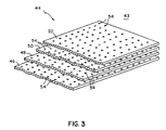
- the air flow controlling means 44 is schematically represented in Fig. 2 and is shown in Fig. 3 and comprises four plates 46, 48, 50, 52 which are disposed horizontally, one above the other, in spaced relationship from one another. Each of the plates is contiguous at its periphery with the enclosure 10.
- the plates serve to divide the interior of the enclosure into two chambers, that above the plates constituting a plenum chamber 43 into which air is introduced through the ducts 42 and that below the plates being the region within which the hopper 18, the support roller 22, and, in use, the curtain 20 are disposed.
- the plates 46 to 52 have perforations 54 and it is arranged that perforations in adjacent plates are not aligned vertically. In this way, air introduced into the plenum chamber above the plates has to follow a tortuous path through perforations in adjacent plates as it flows downwards away from the plenum chamber.
- the total area of perforations 54 in each plate and the rate of feed of air through the ducts into the plenum chamber are so chosen that the air flow rate around the hopper 18 and liquid curtain 20 is uniform and the velocity is such that the falling liquid in the curtain is not disturbed, in other words, it is neither materially accelerated nor decelerated relative to a still air condition, and it is not deflected from a plane it would adapt free falling in still air.
- the air velocity may be of the order of about 5.08 cm/sec (10 ft/min), directed approximately vertically downwards.
- the speed of the air flow just below the controlling means 44 is somewhat higher than the speed desired around the hopper and curtain.
- One particular form of air flow controlling means have been described which provide downstream flow speeds which are substantially uniform in a plane transverse to the direction of flow.
- other forms of flow controlling means may be used and are well known to those skilled in the art.
- ducts 55 open to the interior of the enclosure.
- the positioning and relative sizing of the ducts 55 are so selected as to enhance the uniformity of flow rate and the approximately vertically downwards flow direction, around the hopper and curtain. The positions and relative sizes will vary from installation to installation.
- the means for controlling the outflow rate includes blower means 57 which are so controlled as to maintain the supra-ambient pressure in the enclosure.
- the blower means is preferable over simple throttling means, in the present embodiment, because the outflowing air is ducted to a location external of the coating room because it contains solvents from the liquid which have evaporated into the air in the enclosure.
- Diagrammatically represented at 56 in Fig. 1 are means for blowing air down the ducts 42 and for conditioning the air in humidity, temperature and cleanliness before it passes into the ducts 42.
- web 24 is moved through the slot in the enclosure wall 33, to the support roller 22 about guide rollers 26, 28, passes around the support roller 22 and moves away from the support roller 22 about guide rollers 30, 32. After leaving the guide roller 32, the web passes through the other slot in the enclosure wall 33 to the exterior of the enclosure and thence onwards to driers and other devices.
- Liquids to be coated on the web 24 are supplied to the hopper 18 and, in known manner, are caused to flow out of slots in the inclined upper, slide surface of the hopper so that they flow down the slide surface as discrete layers, forming a composite layer which falls off the lip of the hopper. In falling off the lip of the hopper 18, the composite layer forms the falling curtain 20.
- the liquids in the curtain impinge on the web 24 where it is on the support roller 22 and form a uniform layer thereon.
- Air is heated to a temperature somewhat in excess of the temperature of the liquids in the curtain 20, in the conditioning and blowing means 56.
- the excess temperature is to allow for cooling by the time the air is in the region of the liquid in the curtain 20.
- the humidity is adjusted in the means 56 so that no condensation occurs within the enclosure even though solvent or vehicle in the liquids in the curtain evaporates.
- the conditioning means also cleans the air thereby removing all particles which, if they became entrained in the coating liquids, would cause defects in the coated web.
- the means 56 also serve to blow conditioned air into the ducts 42 at a rate appropriate for causing an air speed within the enclosure adjacent the curtain of about 5.08 cm/sec (10 ft/min).
- the rate of feed of air to the plenum is such as to produce an air speed in the region of the curtain of about 5.08 cm/sec (10 ft/min). Such a speed is sufficient to prevent the build up of solvent or vehicle evaporating from the liquids in the curtain, but is not so high as to create any undesirable effects on the curtain.
- the air After passing downwards past the curtain and support roller, the air continues downwards into the lowest region of the enclosure 10 from which it leaves through the ducts 55. Because the change in air flow pattern associated with flowing out of the ducts 55 is well below the curtain, there is no adverse effect on the curtain caused by such change in flow pattern.
- the air pressure within the enclosure 10 is maintained slightly above the pressure outside the enclosure so that air currents, perhaps containing dust particles and probably with a temperature and a humidity different to that delivered by the ducts 42, do not enter the enclosure through openings it may intentionally or inadvertently have.
- the air supplied to the interior of the enclosure has a temperature approximately that of the coating liquids, all equipment, such as the mounts for the hopper, the support roller and the guide rollers, is maintained at the same temperature as the coating liquids. Thus, there is nothing above the web adjacent the hopper or above the hopper which could rain droplets of condensed solvent or vehicle onto the web or the coating liquids. Even if there should be any condensation outside the enclosure and above the hopper, the enclosure acts as an umbrella.
Abstract
Description
- This invention relates to curtain coating webs or articles with liquid.
- In the art of curtain coating, such as is conducted in the photographic industry for coating layers of materials onto a support web for forming photographic film and paper, it is known that air flow adjacent the curtain can disturb the curtain and cause defects in the coating on the web. It is also known that it is impossible to render a coating room free of air currents because it is necessary to change the atmosphere in the room, it is necessary for people to enter and leave the room through doors, and there are temperature differentials which cause air currents. Likewise, it has been found impossible to render a coating room completely free of dust and such dust gets caught up in the air currents and carried onto the coating liquids.
- Attempts have been made to reduce the disturbing effects on the coating of such ambient air currents.
- U.S. Patent No. 4,287,240, issued September 1, 1981 to Thomas R. O'Connor, describes a coating apparatus provided with a protective shield. The coating apparatus therein described includes a hopper for forming a layer of liquid and for forming the layer into a curtain falling under gravity. A web to be coated is trained about a support roller which is disposed with its axis of rotation parallel to the plane of the curtain and so that the curtain impinges on the web while the web is on the support roller. The web approaches and leaves the support roller substantially horizontally. Disposed about the hopper and extending down as far as just above the web approaching the support roller, is a foraminous shield. The shield is substantially box shaped, with its sixth, the bottom, side open. The shield is formed from fine-mesh metal screening and is of double walled construction. The shield was intended to diffuse air currents impinging thereon so that their velocity is decreased, with a resulting decrease in their ability to disturb the flow of coating liquid. Indeed, it has been found that the residual air currents are necessary to prevent the build-up of water or solvent vapor inside the shield, the water or solvent vapor having evaporated from the liquid intended to form the coating. However, it has been found that the protective shield described in Patent no. 4,287,240 does no more than was intended of it, namely to reduce, but not eliminate, the effects of the ambient air currents. It has been found that it does not eliminate the adverse effects of currents in air around the hopper and curtain including disturbance of the curtain. Furthermore, the air contacting the liquids in the curtain is the air of the coating room which contains dust particles even though the most stringent efforts may be made to achieve clean air.
- The specification of PCT International Patent Application Number PCT/US89/03082 which was published under International Publication Number WO 90/01178, with Kenneth Ruschak named as inventor, describes another form of shield for protecting the flow of liquid on a hopper slide surface. The shield in the Ruschak application is imperforate and is disposed in very close overlying relationship to the liquid flowing down the slide surface of the hopper. The Ruschak shield is intended not only to prevent currents in the ambient air impinging on the liquid on the slide surface, which impact would cause disturbances of the liquid flow which would result in imperfections in the coating on the web, but also to prevent convection currents immediately adjacent the liquid caused by a difference in the temperatures of the liquid and the surrounding air. Even such convection currents have been found to cause disturbances in the liquid flow on the slide surface which appear as imperfections in the coating on the web. The Ruschak shield does not overlay the major portion of even one side of the curtain and does nothing to protect the other side of the curtain. It is intended solely to prevent disturbance of the liquid on the slide surface.
- In German Patent Application 2723444, a method wherein a free falling curtain is sucked toward a rigid member by the use of laminar air flow is described. The curtain thus falls in a curved trajectory, i.e. it follows the shape of the rigid member. This member therefore subjects the curtain to air currents which are intended to disturb the natural free falling path that the curtain would follow to the web.
- Problems, in the form of defects in the coating, derived from air currents impinging on the liquid on the slide surface and in the falling curtain, and from dust, remain.
- It is an object of the present invention to avoid the problems derived from air currents impinging on and disturbing the liquid on the slide surface and in the falling curtain.
- The present invention overcomes these problems by providing an enclosure which provides a space around the hopper and the falling curtain, wherein the direction, velocity and quality of air flow may be controlled. Turbulence and dust content are examples of the quality of air flow.
- It is found that convection currents due to a difference in the temperature of the coating liquid and the air flowing in the enclosure occur, then the temperature of the air introduced into the enclosure is, in accordance with a preferred embodiment of the present invention, controlled so as to approximate the temperature of the falling liquid.
- Advantageously, the humidity is controlled so that condensation within the enclosure is avoided.
- It has been found that in certain coating processes, advantages are achieved if the velocity of the air flowing substantially vertically downwards around the falling liquids is about 5.08 cm/sec (10 ft/min).
- An embodiment of the present invention will now be described, by way of example, with reference to the accompanying drawings, in which:
- Fig. 1 is a perspective view form above and to a side, of apparatus in accordance with the present invention;
- Fig. 2 is a side elevation of the apparatus represented in Fig. 1; and
- Fig. 3 is a perspective view of a component in the form of air flow controlling means, of the apparatus within the enclosure.
- The apparatus illustrated in figs. 1 and 2 of the accompanying drawings, includes an
enclosure 10 supported bycolumns 14 extending up from afloor 12. Theenclosure 10 is imperforate and is formed of sheet metal except where awindow 16 is provided. The window is glazed. The sheet metal is laminated with insulating material so that even if the temperature inside the enclosure is greater than that outside the enclosure and the humidity inside the enclosure is high, there can be no chance of condensation on the inside of the enclosure and hence there can be no chance of condensate falling as droplets within the enclosure. - Within the
enclosure 10, and only schematically represented in Fig. 2, is acoating hopper 18, of known form, which forms liquids to be coated into a fallingcurtain 20. The hopper is disposed above asupport roller 22, the axis of rotation of which is parallel to the plane ofcurtain 20. - A
web 24 to be coated is supported for movement through the curtain by means which in the present embodiment is thesupport roller 22, and its path to thesupport roller 22 is defined byguide rollers support roller 22 is defined byguide rollers guide rollers horizontal wall 33 of theenclosure 10. The slots allow passage of theweb 24 into and out of theenclosure 10. The slots are slightly longer than the width of theweb 24 and may be of the order of 2.54 cm (1 inch) wide. - The
hopper 18, thesupport roller 22, theguide rollers supports 14. - The shape of the upper left hand portion of the
enclosure 10, as seen in Fig. 2, is not material to the present invention but is dictated by the presence of other equipment in this region. - The right hand, as seen in Fig. 2, wall 36 (visible in Fig. 1) of the enclosure is in part formed by a
door 38 which can slide away upwards into anextension 40 of theenclosure 10. - Two
ducts 42 are provided for the introduction of air to the uppermost region of the interior of theenclosure 10. Below the level of the bottom of theducts 42, but well above thehopper 18, there is provided means 44 for controlling the flow of air. The air flow controllingmeans 44 is schematically represented in Fig. 2 and is shown in Fig. 3 and comprises fourplates enclosure 10. The plates serve to divide the interior of the enclosure into two chambers, that above the plates constituting aplenum chamber 43 into which air is introduced through theducts 42 and that below the plates being the region within which thehopper 18, thesupport roller 22, and, in use, thecurtain 20 are disposed. - The
plates 46 to 52 haveperforations 54 and it is arranged that perforations in adjacent plates are not aligned vertically. In this way, air introduced into the plenum chamber above the plates has to follow a tortuous path through perforations in adjacent plates as it flows downwards away from the plenum chamber. The total area ofperforations 54 in each plate and the rate of feed of air through the ducts into the plenum chamber are so chosen that the air flow rate around thehopper 18 andliquid curtain 20 is uniform and the velocity is such that the falling liquid in the curtain is not disturbed, in other words, it is neither materially accelerated nor decelerated relative to a still air condition, and it is not deflected from a plane it would adapt free falling in still air. In one embodiment, the air velocity may be of the order of about 5.08 cm/sec (10 ft/min), directed approximately vertically downwards. In the present embodiment, because the enclosure is not of uniform cross-sectional areas in different horizontal planes, the speed of the air flow just below the controlling means 44 is somewhat higher than the speed desired around the hopper and curtain. One particular form of air flow controlling means have been described which provide downstream flow speeds which are substantially uniform in a plane transverse to the direction of flow. However, it is to be understood that other forms of flow controlling means may be used and are well known to those skilled in the art. - There are means for allowing air to flow out of the lower region of the enclosure, which, in the present embodiment, are
ducts 55 open to the interior of the enclosure. The positioning and relative sizing of theducts 55 are so selected as to enhance the uniformity of flow rate and the approximately vertically downwards flow direction, around the hopper and curtain. The positions and relative sizes will vary from installation to installation. There are means associated with theducts 55 for controlling the rate of flow of air out of the enclosure so that a pressure may be maintained in theenclosure 10 which is higher than the pressure outside the enclosure. In the present embodiment, the means for controlling the outflow rate includes blower means 57 which are so controlled as to maintain the supra-ambient pressure in the enclosure. The blower means is preferable over simple throttling means, in the present embodiment, because the outflowing air is ducted to a location external of the coating room because it contains solvents from the liquid which have evaporated into the air in the enclosure. - Diagrammatically represented at 56 in Fig. 1 are means for blowing air down the
ducts 42 and for conditioning the air in humidity, temperature and cleanliness before it passes into theducts 42. - In operation,
web 24 is moved through the slot in theenclosure wall 33, to thesupport roller 22 aboutguide rollers support roller 22 and moves away from thesupport roller 22 aboutguide rollers guide roller 32, the web passes through the other slot in theenclosure wall 33 to the exterior of the enclosure and thence onwards to driers and other devices. Liquids to be coated on theweb 24 are supplied to thehopper 18 and, in known manner, are caused to flow out of slots in the inclined upper, slide surface of the hopper so that they flow down the slide surface as discrete layers, forming a composite layer which falls off the lip of the hopper. In falling off the lip of thehopper 18, the composite layer forms the fallingcurtain 20. The liquids in the curtain impinge on theweb 24 where it is on thesupport roller 22 and form a uniform layer thereon. - Air is heated to a temperature somewhat in excess of the temperature of the liquids in the
curtain 20, in the conditioning and blowing means 56. The excess temperature is to allow for cooling by the time the air is in the region of the liquid in thecurtain 20. The humidity is adjusted in themeans 56 so that no condensation occurs within the enclosure even though solvent or vehicle in the liquids in the curtain evaporates. The conditioning means also cleans the air thereby removing all particles which, if they became entrained in the coating liquids, would cause defects in the coated web. The means 56 also serve to blow conditioned air into theducts 42 at a rate appropriate for causing an air speed within the enclosure adjacent the curtain of about 5.08 cm/sec (10 ft/min). Air leaving theducts 42 enters theplenum chamber 43 portion of the interior of the enclosure above the air flow controlling means 44 in the form of theplates perforations 54 in the plates 46-52 and in so doing it is given a substantially uniform velocity. The rate of feed of air to the plenum is such as to produce an air speed in the region of the curtain of about 5.08 cm/sec (10 ft/min). Such a speed is sufficient to prevent the build up of solvent or vehicle evaporating from the liquids in the curtain, but is not so high as to create any undesirable effects on the curtain. After passing downwards past the curtain and support roller, the air continues downwards into the lowest region of theenclosure 10 from which it leaves through theducts 55. Because the change in air flow pattern associated with flowing out of theducts 55 is well below the curtain, there is no adverse effect on the curtain caused by such change in flow pattern. - The air pressure within the
enclosure 10 is maintained slightly above the pressure outside the enclosure so that air currents, perhaps containing dust particles and probably with a temperature and a humidity different to that delivered by theducts 42, do not enter the enclosure through openings it may intentionally or inadvertently have. - Because the air supplied to the interior of the enclosure has a temperature approximately that of the coating liquids, all equipment, such as the mounts for the hopper, the support roller and the guide rollers, is maintained at the same temperature as the coating liquids. Thus, there is nothing above the web adjacent the hopper or above the hopper which could rain droplets of condensed solvent or vehicle onto the web or the coating liquids. Even if there should be any condensation outside the enclosure and above the hopper, the enclosure acts as an umbrella.
- While the preferred embodiment of the present invention has been described in which a web is coated with liquids, it is to be understood that the present invention is applicable to the coating of objects, such as, for example, sheets of material or three-dimensional bodies, with liquids.
- The invention has been described in detail with particular reference to a presently preferred embodiment, but it will be understood that variations and modifications can be effected within the scope of the invention as defined by the appended claims.
Claims (16)
- Apparatus for coating a web (24) or object with a liquid using a hopper (18) for forming a layer of liquid and for forming said layer into a curtain (20) falling under gravity, means (22) for supporting the web (24) or object for movement through the curtain (20), an enclosure (10) enclosing said hopper (18) and said means (22) for supporting the web (24) or object and, in use, the curtain (20) characterized by:
means (42) for introducing a flow of air into an upper region of said enclosure (10); and
means (55) for allowing air to flow out of a lower region of the enclosure (10), whereby the flow of air is substantially vertically downwards in the region of the curtain (20) and is of such low velocity that disturbance of the curtain is avoided. - Apparatus as claimed in claim 1, further characterized by:
means (56) for heating the air prior to introduction into the enclosure (10) whereby the temperature of the air in the region of the curtain is approximately the same as the temperature of liquid in the curtain. - Apparatus as claimed in claim 1, further characterized in that:
said means for introducing air is adapted to introduce air at a rate such that the velocity of the air around the falling curtain is about 5.08 cm/sec (10 ft/min), whereby detrimental effects to the coating, caused by disturbance of the curtain by the air flow, are avoided. - Apparatus as claimed in claim 1, further characterized by:
means (44) controlling the flow of air and adapted to form the flow of air introduced into the enclosure, into a non-turbulent substantially vertical downwards flow. - Apparatus as claimed in claim 1, further characterized in that:
the means (55) for allowing air to flow out of the lower region of the enclosure includes means to restrict the air flow whereby the pressure within the enclosure is higher than the pressure outside the enclosure. - Apparatus as claimed in claim 1, further characterized by:
means for adjusting the humidity of the air prior to introduction into the enclosure. - Apparatus as claimed in claim 6, further characterized in that:
said means (56) for introducing air is adapted to introduce air at a rate such that the velocity of the air around the falling curtain is about 5.08 cm/sec (10 ft/min), whereby detrimental effects to the coating, caused by disturbance of the curtain by the air flow, are avoided. - Apparatus as claimed in claim 1, further characterized by:
means (56) for cleaning the air prior to introduction into the enclosure. - A method of coating a web (24) or object with a liquid by providing a hopper (18) for forming a layer of liquid and for forming said layer into a curtain (20) falling under gravity, supporting and moving said web (24) or object through the curtain (20), providing an enclosure (10) around said hopper (18) and the curtain (20) and the web (24) or object where it is impinged by the liquid in the curtain characterized by:
introducing a flow of air into an upper region of the enclosure; and
allowing air to flow out of a lower region of the enclosure, whereby the flow of air is substantially vertically downwards in the region of the curtain and is of such low velocity that disturbance of the curtain is avoided. - A method as claimed in claim 9, further characterized by:
maintaining the pressure of air in the enclosure at a pressure above the pressure of air outside the enclosure. - A method as claimed in claim 9 or 10, further characterized by:
heating the air prior to introduction into the enclosure whereby the temperature of the air in the region of the curtain is approximately the same as the temperature of liquid in the curtain. - A method as claimed in claim 9 or 10, further characterized by:
introducing air into the enclosure at a rate such that the velocity of the air around the falling curtain is about 5.08 cm/sec (10/ft/min), whereby detrimental effects to the coating, caused by disturbance of the curtain by the air flow, are avoided. - A method as claimed in claim 9 or 10, further characterized by:
controlling the flow of air so as to form the flow of air introduced into the enclosure into a non-turbulent substantially downwards flow of air around the curtain. - A method as claimed in claim 9 or 10, further characterized by:
adjusting the humidity of the air to be introduced -into the enclosure so that there is an absence both of condensation within the enclosure and of excessive evaporation of liquid from the curtain. - A method as claimed in claim 9 or 10, further characterized by:
controlling the rate and the humidity of the flow of air introduced into the enclosure, whereby there is an absence of condensation in the enclosure. - A method as claimed in claim 9 or 10, further characterized by:
cleaning the air to be introduced into the enclosure.
Applications Claiming Priority (3)
| Application Number | Priority Date | Filing Date | Title |
|---|---|---|---|
| US55980690A | 1990-07-30 | 1990-07-30 | |
| US559806 | 1990-07-30 | ||
| PCT/US1991/005248 WO1992002851A2 (en) | 1990-07-30 | 1991-07-24 | Apparatus and method for curtain coating |
Publications (2)
| Publication Number | Publication Date |
|---|---|
| EP0542809A1 EP0542809A1 (en) | 1993-05-26 |
| EP0542809B1 true EP0542809B1 (en) | 1995-07-05 |
Family
ID=24235102
Family Applications (1)
| Application Number | Title | Priority Date | Filing Date |
|---|---|---|---|
| EP91914065A Expired - Lifetime EP0542809B1 (en) | 1990-07-30 | 1991-07-24 | Apparatus and method for curtain coating |
Country Status (4)
| Country | Link |
|---|---|
| EP (1) | EP0542809B1 (en) |
| JP (1) | JPH07502450A (en) |
| DE (1) | DE69111069T2 (en) |
| WO (1) | WO1992002851A2 (en) |
Families Citing this family (1)
| Publication number | Priority date | Publication date | Assignee | Title |
|---|---|---|---|---|
| DE59409768D1 (en) * | 1994-09-27 | 2001-07-05 | Ilford Imaging Ch Gmbh | Method and device for curtain coating of a moving support |
Family Cites Families (3)
| Publication number | Priority date | Publication date | Assignee | Title |
|---|---|---|---|---|
| GB1559701A (en) * | 1976-05-26 | 1980-01-23 | Ciba Geigy Ag | Curtain coating |
| US4287240A (en) * | 1980-04-11 | 1981-09-01 | Eastman Kodak Company | Coating apparatus provided with a protective shield |
| WO1990001178A1 (en) * | 1988-07-28 | 1990-02-08 | Eastman Kodak Company | Coating apparatus provided with a protective shield |
-
1991
- 1991-07-24 EP EP91914065A patent/EP0542809B1/en not_active Expired - Lifetime
- 1991-07-24 DE DE69111069T patent/DE69111069T2/en not_active Expired - Lifetime
- 1991-07-24 WO PCT/US1991/005248 patent/WO1992002851A2/en active IP Right Grant
- 1991-07-24 JP JP3513096A patent/JPH07502450A/en active Pending
Also Published As
| Publication number | Publication date |
|---|---|
| JPH07502450A (en) | 1995-03-16 |
| EP0542809A1 (en) | 1993-05-26 |
| WO1992002851A3 (en) | 1992-04-02 |
| DE69111069T2 (en) | 1996-03-14 |
| WO1992002851A2 (en) | 1992-02-20 |
| DE69111069D1 (en) | 1995-08-10 |
Similar Documents
| Publication | Publication Date | Title |
|---|---|---|
| EP0074405B1 (en) | Apparatus for drying coated sheet material | |
| US5114759A (en) | Apparatus and method for curtain coating | |
| KR0135080B1 (en) | Process and device for drying a liquid layer applied to a moving carrier material | |
| US5906862A (en) | Apparatus and method for drying a coating on a substrate | |
| US5881476A (en) | Apparatus and method for drying a coating on a substrate employing multiple drying subzones | |
| US4287240A (en) | Coating apparatus provided with a protective shield | |
| US5621983A (en) | Apparatus and method for deckeling excess air when drying a coating on a substrate | |
| US6015593A (en) | Method for drying a coating on a substrate and reducing mottle | |
| US6018886A (en) | Effect of air baffle design on mottle in solvent coatings | |
| FI111478B (en) | Spray coating method and apparatus | |
| US11434607B2 (en) | Curtain application unit and method for applying an application medium | |
| US3404025A (en) | Method and apparatus for coating a sheet or web | |
| EP0542809B1 (en) | Apparatus and method for curtain coating | |
| US2718065A (en) | Humidifying apparatus | |
| US3383239A (en) | Air impingement apparatus and process to control edge flow in coating procedures | |
| EP0427753B1 (en) | Coating apparatus provided with a protective shield | |
| US20020031608A1 (en) | Coating and drying method | |
| US5342446A (en) | Apparatus for coating a continuous web | |
| JP3033270B2 (en) | Exhaust device | |
| FI113790B (en) | Method and apparatus for calendering | |
| AU2004265466A1 (en) | Method and device for drying a non-metallic coating on a steel band | |
| JPH0791830A (en) | Heat treatment device for web |
Legal Events
| Date | Code | Title | Description |
|---|---|---|---|
| PUAI | Public reference made under article 153(3) epc to a published international application that has entered the european phase |
Free format text: ORIGINAL CODE: 0009012 |
|
| 17P | Request for examination filed |
Effective date: 19930212 |
|
| AK | Designated contracting states |
Kind code of ref document: A1 Designated state(s): AT BE CH DE DK ES FR GB GR IT LI LU NL SE |
|
| 17Q | First examination report despatched |
Effective date: 19941121 |
|
| RBV | Designated contracting states (corrected) |
Designated state(s): DE FR GB IT NL |
|
| GRAA | (expected) grant |
Free format text: ORIGINAL CODE: 0009210 |
|
| ITF | It: translation for a ep patent filed |
Owner name: BARZANO' E ZANARDO MILANO S.P.A. |
|
| AK | Designated contracting states |
Kind code of ref document: B1 Designated state(s): DE FR GB IT NL |
|
| REF | Corresponds to: |
Ref document number: 69111069 Country of ref document: DE Date of ref document: 19950810 |
|
| ET | Fr: translation filed | ||
| PLBE | No opposition filed within time limit |
Free format text: ORIGINAL CODE: 0009261 |
|
| STAA | Information on the status of an ep patent application or granted ep patent |
Free format text: STATUS: NO OPPOSITION FILED WITHIN TIME LIMIT |
|
| 26N | No opposition filed | ||
| PGFP | Annual fee paid to national office [announced via postgrant information from national office to epo] |
Ref country code: GB Payment date: 19980623 Year of fee payment: 8 |
|
| PGFP | Annual fee paid to national office [announced via postgrant information from national office to epo] |
Ref country code: FR Payment date: 19980707 Year of fee payment: 8 |
|
| PG25 | Lapsed in a contracting state [announced via postgrant information from national office to epo] |
Ref country code: GB Free format text: LAPSE BECAUSE OF NON-PAYMENT OF DUE FEES Effective date: 19990724 |
|
| PG25 | Lapsed in a contracting state [announced via postgrant information from national office to epo] |
Ref country code: FR Free format text: THE PATENT HAS BEEN ANNULLED BY A DECISION OF A NATIONAL AUTHORITY Effective date: 19990731 |
|
| GBPC | Gb: european patent ceased through non-payment of renewal fee |
Effective date: 19990724 |
|
| REG | Reference to a national code |
Ref country code: FR Ref legal event code: ST |
|
| PG25 | Lapsed in a contracting state [announced via postgrant information from national office to epo] |
Ref country code: IT Free format text: LAPSE BECAUSE OF NON-PAYMENT OF DUE FEES;WARNING: LAPSES OF ITALIAN PATENTS WITH EFFECTIVE DATE BEFORE 2007 MAY HAVE OCCURRED AT ANY TIME BEFORE 2007. THE CORRECT EFFECTIVE DATE MAY BE DIFFERENT FROM THE ONE RECORDED. Effective date: 20050724 |
|
| PGFP | Annual fee paid to national office [announced via postgrant information from national office to epo] |
Ref country code: NL Payment date: 20100709 Year of fee payment: 20 |
|
| PGFP | Annual fee paid to national office [announced via postgrant information from national office to epo] |
Ref country code: DE Payment date: 20100730 Year of fee payment: 20 |
|
| REG | Reference to a national code |
Ref country code: DE Ref legal event code: R071 Ref document number: 69111069 Country of ref document: DE |
|
| REG | Reference to a national code |
Ref country code: DE Ref legal event code: R071 Ref document number: 69111069 Country of ref document: DE |
|
| REG | Reference to a national code |
Ref country code: NL Ref legal event code: V4 Effective date: 20110724 |
|
| PG25 | Lapsed in a contracting state [announced via postgrant information from national office to epo] |
Ref country code: NL Free format text: LAPSE BECAUSE OF EXPIRATION OF PROTECTION Effective date: 20110724 |
|
| PG25 | Lapsed in a contracting state [announced via postgrant information from national office to epo] |
Ref country code: DE Free format text: LAPSE BECAUSE OF EXPIRATION OF PROTECTION Effective date: 20110725 |