EP0542415A1 - Barrier fence - Google Patents
Barrier fence Download PDFInfo
- Publication number
- EP0542415A1 EP0542415A1 EP92308602A EP92308602A EP0542415A1 EP 0542415 A1 EP0542415 A1 EP 0542415A1 EP 92308602 A EP92308602 A EP 92308602A EP 92308602 A EP92308602 A EP 92308602A EP 0542415 A1 EP0542415 A1 EP 0542415A1
- Authority
- EP
- European Patent Office
- Prior art keywords
- cross
- members
- uprights
- barrier
- barrier fence
- Prior art date
- Legal status (The legal status is an assumption and is not a legal conclusion. Google has not performed a legal analysis and makes no representation as to the accuracy of the status listed.)
- Withdrawn
Links
- 230000004888 barrier function Effects 0.000 title claims abstract description 40
- 230000008878 coupling Effects 0.000 claims description 12
- 238000010168 coupling process Methods 0.000 claims description 12
- 238000005859 coupling reaction Methods 0.000 claims description 12
- 230000010006 flight Effects 0.000 description 2
- 238000009434 installation Methods 0.000 description 1
Images
Classifications
-
- E—FIXED CONSTRUCTIONS
- E04—BUILDING
- E04H—BUILDINGS OR LIKE STRUCTURES FOR PARTICULAR PURPOSES; SWIMMING OR SPLASH BATHS OR POOLS; MASTS; FENCING; TENTS OR CANOPIES, IN GENERAL
- E04H1/00—Buildings or groups of buildings for dwelling or office purposes; General layout, e.g. modular co-ordination or staggered storeys
- E04H1/12—Small buildings or other erections for limited occupation, erected in the open air or arranged in buildings, e.g. kiosks, waiting shelters for bus stops or for filling stations, roofs for railway platforms, watchmen's huts or dressing cubicles
- E04H1/1205—Small buildings erected in the open air
- E04H1/1211—Waiting shelters for bus stops
-
- E—FIXED CONSTRUCTIONS
- E04—BUILDING
- E04H—BUILDINGS OR LIKE STRUCTURES FOR PARTICULAR PURPOSES; SWIMMING OR SPLASH BATHS OR POOLS; MASTS; FENCING; TENTS OR CANOPIES, IN GENERAL
- E04H17/00—Fencing, e.g. fences, enclosures, corrals
- E04H17/14—Fences constructed of rigid elements, e.g. with additional wire fillings or with posts
- E04H17/1413—Post-and-rail fences, e.g. without vertical cross-members
- E04H17/1447—Details of connections between rails and posts
- E04H17/1448—Adjustable, angled or hinged connections
-
- E—FIXED CONSTRUCTIONS
- E04—BUILDING
- E04B—GENERAL BUILDING CONSTRUCTIONS; WALLS, e.g. PARTITIONS; ROOFS; FLOORS; CEILINGS; INSULATION OR OTHER PROTECTION OF BUILDINGS
- E04B1/00—Constructions in general; Structures which are not restricted either to walls, e.g. partitions, or floors or ceilings or roofs
- E04B1/343—Structures characterised by movable, separable, or collapsible parts, e.g. for transport
- E04B1/344—Structures characterised by movable, separable, or collapsible parts, e.g. for transport with hinged parts
- E04B1/3441—Structures characterised by movable, separable, or collapsible parts, e.g. for transport with hinged parts with articulated bar-shaped elements
-
- E—FIXED CONSTRUCTIONS
- E04—BUILDING
- E04B—GENERAL BUILDING CONSTRUCTIONS; WALLS, e.g. PARTITIONS; ROOFS; FLOORS; CEILINGS; INSULATION OR OTHER PROTECTION OF BUILDINGS
- E04B2/00—Walls, e.g. partitions, for buildings; Wall construction with regard to insulation; Connections specially adapted to walls
- E04B2/74—Removable non-load-bearing partitions; Partitions with a free upper edge
- E04B2/7407—Removable non-load-bearing partitions; Partitions with a free upper edge assembled using frames with infill panels or coverings only; made-up of panels and a support structure incorporating posts
- E04B2/7416—Removable non-load-bearing partitions; Partitions with a free upper edge assembled using frames with infill panels or coverings only; made-up of panels and a support structure incorporating posts with free upper edge, e.g. for use as office space dividers
- E04B2/7433—Removable non-load-bearing partitions; Partitions with a free upper edge assembled using frames with infill panels or coverings only; made-up of panels and a support structure incorporating posts with free upper edge, e.g. for use as office space dividers with panels and support posts
- E04B2/7435—Glazing details
-
- E—FIXED CONSTRUCTIONS
- E04—BUILDING
- E04B—GENERAL BUILDING CONSTRUCTIONS; WALLS, e.g. PARTITIONS; ROOFS; FLOORS; CEILINGS; INSULATION OR OTHER PROTECTION OF BUILDINGS
- E04B2/00—Walls, e.g. partitions, for buildings; Wall construction with regard to insulation; Connections specially adapted to walls
- E04B2/74—Removable non-load-bearing partitions; Partitions with a free upper edge
- E04B2/7407—Removable non-load-bearing partitions; Partitions with a free upper edge assembled using frames with infill panels or coverings only; made-up of panels and a support structure incorporating posts
- E04B2/7416—Removable non-load-bearing partitions; Partitions with a free upper edge assembled using frames with infill panels or coverings only; made-up of panels and a support structure incorporating posts with free upper edge, e.g. for use as office space dividers
- E04B2/7433—Removable non-load-bearing partitions; Partitions with a free upper edge assembled using frames with infill panels or coverings only; made-up of panels and a support structure incorporating posts with free upper edge, e.g. for use as office space dividers with panels and support posts
- E04B2/7438—Removable non-load-bearing partitions; Partitions with a free upper edge assembled using frames with infill panels or coverings only; made-up of panels and a support structure incorporating posts with free upper edge, e.g. for use as office space dividers with panels and support posts with adjustable angular connection of panels to posts
-
- E—FIXED CONSTRUCTIONS
- E04—BUILDING
- E04F—FINISHING WORK ON BUILDINGS, e.g. STAIRS, FLOORS
- E04F11/00—Stairways, ramps, or like structures; Balustrades; Handrails
- E04F11/18—Balustrades; Handrails
- E04F11/181—Balustrades
- E04F11/1817—Connections therefor
- E04F11/1834—Connections therefor with adjustable angle, e.g. pivotal connections
-
- E—FIXED CONSTRUCTIONS
- E04—BUILDING
- E04H—BUILDINGS OR LIKE STRUCTURES FOR PARTICULAR PURPOSES; SWIMMING OR SPLASH BATHS OR POOLS; MASTS; FENCING; TENTS OR CANOPIES, IN GENERAL
- E04H17/00—Fencing, e.g. fences, enclosures, corrals
- E04H17/14—Fences constructed of rigid elements, e.g. with additional wire fillings or with posts
- E04H17/1413—Post-and-rail fences, e.g. without vertical cross-members
- E04H17/1417—Post-and-rail fences, e.g. without vertical cross-members with vertical cross-members
- E04H17/1426—Picket fences
- E04H17/143—Picket fences with separate pickets attached to the side of the horizontal members
-
- E—FIXED CONSTRUCTIONS
- E04—BUILDING
- E04H—BUILDINGS OR LIKE STRUCTURES FOR PARTICULAR PURPOSES; SWIMMING OR SPLASH BATHS OR POOLS; MASTS; FENCING; TENTS OR CANOPIES, IN GENERAL
- E04H17/00—Fencing, e.g. fences, enclosures, corrals
- E04H17/14—Fences constructed of rigid elements, e.g. with additional wire fillings or with posts
- E04H17/1413—Post-and-rail fences, e.g. without vertical cross-members
- E04H17/1447—Details of connections between rails and posts
-
- E—FIXED CONSTRUCTIONS
- E04—BUILDING
- E04H—BUILDINGS OR LIKE STRUCTURES FOR PARTICULAR PURPOSES; SWIMMING OR SPLASH BATHS OR POOLS; MASTS; FENCING; TENTS OR CANOPIES, IN GENERAL
- E04H6/00—Buildings for parking cars, rolling-stock, aircraft, vessels or like vehicles, e.g. garages
- E04H6/02—Small garages, e.g. for one or two cars
Definitions
- This invention relates to a barrier fence for permanent or temporary installation on a site, in particular to a barrier fence comprising uprights and cross-members.
- British Patent No 1285577 describes a barrier system which permits a certain amount of vertical flexibility in assembly and some, very limited flexibility in the horizontal plane. This system, however, can be installed only in straight lines or on shallow curves, eg alongside bends in roads.
- barrier elements comprising vertical end-posts connected by horizontal cross-members are connected together by male/female engagement of corresponding lugs and apertures on adjacent elements. Whilst this arrangement permits some flexibility in the angular disposition of adjacent elements in the horizontal plane, it does not enable the barrier to be positioned on inclined surfaces or alongside flights of steps.
- each barrier post accommodates a reel of tape which can be unwound and connected to the next post. This permits complete freedom in the relative positioning of adjacent posts, but the connecting tapes provide only a very flimsy barrier which is easily crossed and is therefore relatively ineffective.
- a barrier fence comprising a row of uprights interconnected by rigid cross-members, the cross-members being pivotally connected to the uprights such that successive cross-members may be aligned at substantially any angle in both the vertical and horizontal planes.
- the barrier fence according to the invention is advantageous primarily in that it can be readily erected, even on a site which is on, or which includes, an inclined surface, using standard components and without the need for surveying. Furthermore, the uprights may be disposed vertically, irrespective of the degree of slope of the site.
- the fact that adjacent sections of the barrier may be disposed at a range of angles in the horizontal plane enables bends to be introduced into the barrier.
- the barrier can be installed on sloping ground or alongside flights of stairs.
- the barrier may also be used as a temporary structure, yet is sturdy and rigid enough to be effective.
- connection between the uprights and the cross-members is pivotal, after the barrier has been erected the structure may be completely rigid.
- the range of angles over which the cross-members may be oriented relative to the uprights in the vertical plane may be 90° or more, in practice 40° is sufficient for most purposes, since a barrier fence would be unlikely to be erected on an incline of greater than 20°.
- successive uprights are preferably connected by a plurality, most preferably by two, cross-members.
- the cross-members are preferably connected by pivotally-mounted vertical slats.
- the cross-member is preferably connected to coupling rings which are rotatably mounted on the uprights.
- the barrier according to the invention may be fixed, in which case the uprights may be embedded in the ground, or may be a temporary structure, in which case some at least of the uprights are provided with a base member or foot to keep the barrier upright.
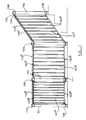
- a barrier comprises a series of vertical posts 101-104 of circular cross-section. Adjacent pairs of posts 101-104 are connected by upper and lower cross-members (105a-d, 106a-d respectively), each pair of which is connected by nine vertical slats 107a-d (slats 107d not being visible in the Figures).
- Each cross-member 105a-d, 106a-d is pivotally connected at each of its ends to a coupling ring 108 which is rotatably mounted on the corresponding post 101-104.
- Each coupling ring 108 is provided with a pair of flanges 109 which receive the end of the cross-member 105a-d, 106a-d, the pivotal connection being completed by a pin 110 passing through apertures in the flanges 109 and cross-member 105a-d, 106a-d.
- Each post 101-104 carries two pairs of coupling rings 108, one pair, located near the top of the post, being for connection to the upper cross-members 105a-d connecting the post to the two adjacent posts, and the other pair, located near the base of the post, for connection to the corresponding lower cross-members 106a-d.
- the upper coupling rings 108 on post 103 are connected to upper cross-members 105b and 105c, and the lower coupling rings to lower cross-members 106b and 106c.
- terminal posts such as 101 may carry only single upper and lower coupling rings.
- the lower pair of coupling rings 108 is supported and spaced from the base of the post by a circumferential flange 111.
- a similar flange 112 is provided at the top of the post 101-104, above the upper pair of coupling rings 108.
- Each upper cross-member 105a-d carries a hand-rail 113a-d which is secured to the upper cross-member 105a-d by screws.
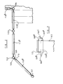
- Figure 3 shows a pair of coupling rings, specifically that at the top of upright 103, in greater detail.
- the pair comprises an upper ring 108a and a lower ring 108b.
- Each ring 108a, 108b is provided with a pair of flanges 109a,109b.
- Each flange 109a,109b is generally semi-circular in side elevation, being joined to the corresponding ring 108a,108b along about half the diameter of the semicircle and overlapping the other ring along the remainder of the diameter. Both rings rotate (prior to assembly of the barrier) freely about the post 103.
- the barrier may be disposed in any desired arrangement.
- the cross-members 105a,106a between posts 101 and 102 make an obtuse angle in the horizontal plane with those 105b,106b between posts 102 and 103.
- Post 104 is fixed on the topmost step of a short flight of steps, the cross-members 105c,106c between posts 103 and 104 being oriented accordingly.
Abstract
A barrier fence comprises a row of uprights (101-104) interconnected by rigid cross-members (105,106). The cross-members (105,106) are pivotally connected to the uprights (101-104) such that successive sections of the barrier can be aligned at any angle in both the vertical and horizontal planes, depending on the desired orientation or the terrain of the site.
Description
- This invention relates to a barrier fence for permanent or temporary installation on a site, in particular to a barrier fence comprising uprights and cross-members.
- Hitherto, where it has been desired to erect a barrier fence comprising uprights and cross-members, great difficulties have been encountered unless the building site is perfectly level. It has been necessary to carry out a detailed survey of the site prior to erection of the fence and to fabricate many of the components to suit the contours of the site. This has added greatly to the time taken to complete the structure, and to the expense thereof.
- British Patent No 1285577 describes a barrier system which permits a certain amount of vertical flexibility in assembly and some, very limited flexibility in the horizontal plane. This system, however, can be installed only in straight lines or on shallow curves, eg alongside bends in roads.
- It is also frequently necessary to erect a temporary barrier, eg for the control of crowds at sporting or other events. In one system for this purpose, rigid barrier elements comprising vertical end-posts connected by horizontal cross-members are connected together by male/female engagement of corresponding lugs and apertures on adjacent elements. Whilst this arrangement permits some flexibility in the angular disposition of adjacent elements in the horizontal plane, it does not enable the barrier to be positioned on inclined surfaces or alongside flights of steps.
- In another known system, each barrier post accommodates a reel of tape which can be unwound and connected to the next post. This permits complete freedom in the relative positioning of adjacent posts, but the connecting tapes provide only a very flimsy barrier which is easily crossed and is therefore relatively ineffective.
- There has now been devised a barrier fence structure comprising uprights and cross-members which overcomes or substantially mitigates the above-mentioned disadvantages.
- According to the invention, there is provided a barrier fence comprising a row of uprights interconnected by rigid cross-members, the cross-members being pivotally connected to the uprights such that successive cross-members may be aligned at substantially any angle in both the vertical and horizontal planes.
- The barrier fence according to the invention is advantageous primarily in that it can be readily erected, even on a site which is on, or which includes, an inclined surface, using standard components and without the need for surveying. Furthermore, the uprights may be disposed vertically, irrespective of the degree of slope of the site.
- In addition, the fact that adjacent sections of the barrier may be disposed at a range of angles in the horizontal plane enables bends to be introduced into the barrier. The barrier can be installed on sloping ground or alongside flights of stairs. The barrier may also be used as a temporary structure, yet is sturdy and rigid enough to be effective.
- Although the connection between the uprights and the cross-members is pivotal, after the barrier has been erected the structure may be completely rigid.
- Although the range of angles over which the cross-members may be oriented relative to the uprights in the vertical plane may be 90° or more, in practice 40° is sufficient for most purposes, since a barrier fence would be unlikely to be erected on an incline of greater than 20°.
- Likewise, although the range of angles over which adjacent sections may be oriented in the horizontal plane may approach 360°, in practice a range of form 90° to 270° is generally sufficient since this allows adjacent sections to be disposed at angles close to right angles.
- To provide a more effective barrier, successive uprights are preferably connected by a plurality, most preferably by two, cross-members. The cross-members are preferably connected by pivotally-mounted vertical slats.
- For orientation in the horizontal plane, the cross-member is preferably connected to coupling rings which are rotatably mounted on the uprights.
- The barrier according to the invention may be fixed, in which case the uprights may be embedded in the ground, or may be a temporary structure, in which case some at least of the uprights are provided with a base member or foot to keep the barrier upright.
- The invention will now be described in more detail, by way of illustration only, with reference to the accompanying drawings, in which
- Figure 1 is a side elevation of a portion of a barrier according to the invention,
- Figure 2 is a plan view of the barrier of Figure 1, and
- Figure 3 is a detailed view of the top portion of an upright forming part of the barrier of Figures 1 and 2.
- Referring first to Figure 1, a barrier comprises a series of vertical posts 101-104 of circular cross-section. Adjacent pairs of posts 101-104 are connected by upper and lower cross-members (105a-d, 106a-d respectively), each pair of which is connected by nine vertical slats 107a-d (slats 107d not being visible in the Figures).
- Each cross-member 105a-d, 106a-d is pivotally connected at each of its ends to a
coupling ring 108 which is rotatably mounted on the corresponding post 101-104. Eachcoupling ring 108 is provided with a pair offlanges 109 which receive the end of the cross-member 105a-d, 106a-d, the pivotal connection being completed by apin 110 passing through apertures in theflanges 109 and cross-member 105a-d, 106a-d. - Each post 101-104 carries two pairs of
coupling rings 108, one pair, located near the top of the post, being for connection to the upper cross-members 105a-d connecting the post to the two adjacent posts, and the other pair, located near the base of the post, for connection to the corresponding lower cross-members 106a-d. For example, theupper coupling rings 108 onpost 103 are connected toupper cross-members 105b and 105c, and the lower coupling rings tolower cross-members 106b and 106c. Of course, terminal posts such as 101 may carry only single upper and lower coupling rings. The lower pair ofcoupling rings 108 is supported and spaced from the base of the post by acircumferential flange 111. Asimilar flange 112 is provided at the top of the post 101-104, above the upper pair ofcoupling rings 108. Each upper cross-member 105a-d carries a hand-rail 113a-d which is secured to the upper cross-member 105a-d by screws. - Figure 3 shows a pair of coupling rings, specifically that at the top of upright 103, in greater detail. The pair comprises an upper ring 108a and a lower ring 108b. Each ring 108a, 108b is provided with a pair of
flanges 109a,109b. Eachflange 109a,109b is generally semi-circular in side elevation, being joined to the corresponding ring 108a,108b along about half the diameter of the semicircle and overlapping the other ring along the remainder of the diameter. Both rings rotate (prior to assembly of the barrier) freely about thepost 103. - In use, the barrier may be disposed in any desired arrangement. As shown in the Figures, the cross-members 105a,106a between
posts posts Post 104 is fixed on the topmost step of a short flight of steps, the cross-members 105c,106c betweenposts
Claims (10)
- A barrier fence comprising a row of uprights (101-104) interconnected by rigid cross-members (105,106), the cross-members (105,106) being pivotally connected to the uprights (101-104) such that successive cross-members (105,106) may be aligned at substantially any angle in both the vertical and horizontal planes.
- A barrier fence as claimed in Claim 1, wherein the range of angles over which the cross-members (105,106) may be oriented relative to the uprights (101-104) in the vertical plane is 90° or more.
- A barrier fence as claimed in Claim 1 or Claim 2, wherein the range of angles over which adjacent sections may be oriented in the horizontal plane includes angles from 90° to 270°.
- A barrier fence as claimed in any one of the preceding claims, wherein successive uprights (101-104) are connected by a plurality of cross-members (105,106).
- A barrier fence as claimed in Claim 4, wherein successive uprights (101-104) are connected by two cross-members (105,106).
- A barrier fence as claimed in Claim 4 or Claim 5, wherein the cross-members (105,106) are connected by pivotally-mounted vertical slats (107).
- A barrier fence as claimed in any one of the preceding claims, wherein the cross-members (105,106) are connected to coupling rings (108)which are rotatably mounted on the uprights (101-104).
- A barrier fence as claimed in Claim 7, wherein at least some of the uprights (101-104) are provided with upper and lower pairs of rotatably mounted coupling rings (108) to which the cross-members (105-106) are pivotally connected.
- A barrier fence as claimed in any one of the preceding claims which is rigid, the uprights (101-104) being embedded in the ground.
- A barrier fence as claimed in any one of Claims 1 to 8, which is a temporary structure, in which some at least of the uprights are provided with a base member or foot.
Applications Claiming Priority (2)
| Application Number | Priority Date | Filing Date | Title |
|---|---|---|---|
| GB919124384A GB9124384D0 (en) | 1991-11-13 | 1991-11-13 | Building structure |
| GB9124384 | 1991-11-13 |
Publications (1)
| Publication Number | Publication Date |
|---|---|
| EP0542415A1 true EP0542415A1 (en) | 1993-05-19 |
Family
ID=10704749
Family Applications (2)
| Application Number | Title | Priority Date | Filing Date |
|---|---|---|---|
| EP92308602A Withdrawn EP0542415A1 (en) | 1991-11-13 | 1992-09-22 | Barrier fence |
| EP92308620A Withdrawn EP0542416A1 (en) | 1991-11-13 | 1992-09-22 | Building structure |
Family Applications After (1)
| Application Number | Title | Priority Date | Filing Date |
|---|---|---|---|
| EP92308620A Withdrawn EP0542416A1 (en) | 1991-11-13 | 1992-09-22 | Building structure |
Country Status (2)
| Country | Link |
|---|---|
| EP (2) | EP0542415A1 (en) |
| GB (1) | GB9124384D0 (en) |
Cited By (6)
| Publication number | Priority date | Publication date | Assignee | Title |
|---|---|---|---|---|
| AT1212U1 (en) * | 1994-11-21 | 1996-12-27 | Mitschjeta Max Ag | FENCE, ESPECIALLY MACHINE PROTECTION FENCE |
| FR2738862A1 (en) * | 1995-09-14 | 1997-03-21 | Gibert Didier | Sectional frame for barrier |
| GB2307256A (en) * | 1995-11-17 | 1997-05-21 | Darfen Ltd | Fence with pivotal connections |
| GB2449666A (en) * | 2007-05-31 | 2008-12-03 | Burbidge Richard Ltd | Handrail connector |
| CN111733738A (en) * | 2020-06-24 | 2020-10-02 | 四川路桥建设集团交通工程有限公司 | Novel isolation fence for expressway and installation method thereof |
| CN112523553A (en) * | 2019-12-13 | 2021-03-19 | 吴岩 | Mine wellhead protection device for mine hoist |
Citations (2)
| Publication number | Priority date | Publication date | Assignee | Title |
|---|---|---|---|---|
| US3960367A (en) * | 1975-05-12 | 1976-06-01 | Spacemaker (Products) Limited | Fence with adjustable vertical panels |
| EP0293337A2 (en) * | 1987-05-28 | 1988-11-30 | ROVERA RESINE S.r.l. | Fixed or mobile fencing with variable inclination |
Family Cites Families (2)
| Publication number | Priority date | Publication date | Assignee | Title |
|---|---|---|---|---|
| FR1326342A (en) * | 1961-07-08 | 1963-05-10 | Anciens Etablissements E Faver | Tent frame |
| FR2232644B1 (en) * | 1973-06-08 | 1976-04-23 | Const Ind |
-
1991
- 1991-11-13 GB GB919124384A patent/GB9124384D0/en active Pending
-
1992
- 1992-09-22 EP EP92308602A patent/EP0542415A1/en not_active Withdrawn
- 1992-09-22 EP EP92308620A patent/EP0542416A1/en not_active Withdrawn
Patent Citations (2)
| Publication number | Priority date | Publication date | Assignee | Title |
|---|---|---|---|---|
| US3960367A (en) * | 1975-05-12 | 1976-06-01 | Spacemaker (Products) Limited | Fence with adjustable vertical panels |
| EP0293337A2 (en) * | 1987-05-28 | 1988-11-30 | ROVERA RESINE S.r.l. | Fixed or mobile fencing with variable inclination |
Cited By (7)
| Publication number | Priority date | Publication date | Assignee | Title |
|---|---|---|---|---|
| AT1212U1 (en) * | 1994-11-21 | 1996-12-27 | Mitschjeta Max Ag | FENCE, ESPECIALLY MACHINE PROTECTION FENCE |
| FR2738862A1 (en) * | 1995-09-14 | 1997-03-21 | Gibert Didier | Sectional frame for barrier |
| GB2307256A (en) * | 1995-11-17 | 1997-05-21 | Darfen Ltd | Fence with pivotal connections |
| GB2307256B (en) * | 1995-11-17 | 1999-05-26 | Darfen Ltd | Fencing system |
| GB2449666A (en) * | 2007-05-31 | 2008-12-03 | Burbidge Richard Ltd | Handrail connector |
| CN112523553A (en) * | 2019-12-13 | 2021-03-19 | 吴岩 | Mine wellhead protection device for mine hoist |
| CN111733738A (en) * | 2020-06-24 | 2020-10-02 | 四川路桥建设集团交通工程有限公司 | Novel isolation fence for expressway and installation method thereof |
Also Published As
| Publication number | Publication date |
|---|---|
| GB9124384D0 (en) | 1992-01-08 |
| EP0542416A1 (en) | 1993-05-19 |
Similar Documents
| Publication | Publication Date | Title |
|---|---|---|
| US5518333A (en) | Studded T-post connector | |
| US4723760A (en) | Picket fence assembly | |
| US7325787B1 (en) | Barrier | |
| US5452880A (en) | Fence coupling | |
| US4763879A (en) | Metal fence post connector | |
| EP0069473B1 (en) | A fence assembly | |
| US4078772A (en) | Stockade fence fixture therefor | |
| US4986513A (en) | Fence connector assembly | |
| US20070170411A1 (en) | Temporary fence | |
| US4951925A (en) | Fence connector assembly | |
| US20050082518A1 (en) | Fencing system | |
| US3410527A (en) | Fence row construction devices | |
| EP0542415A1 (en) | Barrier fence | |
| US6904924B2 (en) | Triangular frame tent | |
| US3879905A (en) | Precast foundation assembly for mobile homes | |
| US20050135878A1 (en) | Temporary barrier | |
| US5120025A (en) | Picket fence joint | |
| EP1312732A2 (en) | Modular fence | |
| US6854227B2 (en) | Anchor bolt locating jig | |
| GB2293402A (en) | Guardrail fencing | |
| GB2235225A (en) | Preventing warping of fence panels | |
| US11377871B2 (en) | Anchoring system for a fence | |
| JPH0528299Y2 (en) | ||
| US4628659A (en) | Iron reinforcing rod structure for reinforcing the base of buildings | |
| KR102059374B1 (en) | Fence with improved ground structure and method of construction thereof |
Legal Events
| Date | Code | Title | Description |
|---|---|---|---|
| PUAI | Public reference made under article 153(3) epc to a published international application that has entered the european phase |
Free format text: ORIGINAL CODE: 0009012 |
|
| AK | Designated contracting states |
Kind code of ref document: A1 Designated state(s): AT BE CH DE DK ES FR GB GR IE IT LI LU MC NL PT SE |
|
| RBV | Designated contracting states (corrected) |
Designated state(s): BE DE DK ES FR GB GR IT NL |
|
| STAA | Information on the status of an ep patent application or granted ep patent |
Free format text: STATUS: THE APPLICATION IS DEEMED TO BE WITHDRAWN |
|
| 18D | Application deemed to be withdrawn |
Effective date: 19931119 |