EP0541777B1 - Akustische logische schaltungen - Google Patents
Akustische logische schaltungen Download PDFInfo
- Publication number
- EP0541777B1 EP0541777B1 EP92912828A EP92912828A EP0541777B1 EP 0541777 B1 EP0541777 B1 EP 0541777B1 EP 92912828 A EP92912828 A EP 92912828A EP 92912828 A EP92912828 A EP 92912828A EP 0541777 B1 EP0541777 B1 EP 0541777B1
- Authority
- EP
- European Patent Office
- Prior art keywords
- ports
- closed
- logic device
- open
- resonant frequency
- Prior art date
- Legal status (The legal status is an assumption and is not a legal conclusion. Google has not performed a legal analysis and makes no representation as to the accuracy of the status listed.)
- Expired - Lifetime
Links
- 239000000463 material Substances 0.000 description 8
- 239000002033 PVDF binder Substances 0.000 description 6
- 230000005540 biological transmission Effects 0.000 description 6
- 238000003475 lamination Methods 0.000 description 5
- 239000000919 ceramic Substances 0.000 description 3
- 229920000642 polymer Polymers 0.000 description 3
- 239000012530 fluid Substances 0.000 description 2
- 229920002981 polyvinylidene fluoride Polymers 0.000 description 2
- 239000003990 capacitor Substances 0.000 description 1
- 239000002131 composite material Substances 0.000 description 1
- 239000004020 conductor Substances 0.000 description 1
- 230000003247 decreasing effect Effects 0.000 description 1
- 238000001514 detection method Methods 0.000 description 1
- 238000010586 diagram Methods 0.000 description 1
- 230000000694 effects Effects 0.000 description 1
- 238000009434 installation Methods 0.000 description 1
- 239000002184 metal Substances 0.000 description 1
- 238000000034 method Methods 0.000 description 1
- 239000002985 plastic film Substances 0.000 description 1
- 229920006255 plastic film Polymers 0.000 description 1
- 238000004886 process control Methods 0.000 description 1
- 230000035945 sensitivity Effects 0.000 description 1
- 239000007787 solid Substances 0.000 description 1
- 238000011144 upstream manufacturing Methods 0.000 description 1
Images


Classifications
-
- G—PHYSICS
- G10—MUSICAL INSTRUMENTS; ACOUSTICS
- G10K—SOUND-PRODUCING DEVICES; METHODS OR DEVICES FOR PROTECTING AGAINST, OR FOR DAMPING, NOISE OR OTHER ACOUSTIC WAVES IN GENERAL; ACOUSTICS NOT OTHERWISE PROVIDED FOR
- G10K15/00—Acoustics not otherwise provided for
-
- G—PHYSICS
- G01—MEASURING; TESTING
- G01S—RADIO DIRECTION-FINDING; RADIO NAVIGATION; DETERMINING DISTANCE OR VELOCITY BY USE OF RADIO WAVES; LOCATING OR PRESENCE-DETECTING BY USE OF THE REFLECTION OR RERADIATION OF RADIO WAVES; ANALOGOUS ARRANGEMENTS USING OTHER WAVES
- G01S15/00—Systems using the reflection or reradiation of acoustic waves, e.g. sonar systems
- G01S15/02—Systems using the reflection or reradiation of acoustic waves, e.g. sonar systems using reflection of acoustic waves
-
- Y—GENERAL TAGGING OF NEW TECHNOLOGICAL DEVELOPMENTS; GENERAL TAGGING OF CROSS-SECTIONAL TECHNOLOGIES SPANNING OVER SEVERAL SECTIONS OF THE IPC; TECHNICAL SUBJECTS COVERED BY FORMER USPC CROSS-REFERENCE ART COLLECTIONS [XRACs] AND DIGESTS
- Y10—TECHNICAL SUBJECTS COVERED BY FORMER USPC
- Y10S—TECHNICAL SUBJECTS COVERED BY FORMER USPC CROSS-REFERENCE ART COLLECTIONS [XRACs] AND DIGESTS
- Y10S367/00—Communications, electrical: acoustic wave systems and devices
- Y10S367/903—Transmit-receive circuitry
Definitions
- Electronic logic devices such as inverters and AND, NAND, OR and NOR gates employ high and low voltage levels to indicate the digital logic 0 and 1 states. Thus two distinct amplitudes or levels of an electrical parameter are used to indicate the two logic states.
- Acoustic transducers or gauges exist in which an acoustic parameter has two distinct levels, and an example is shown and described in United States Patent No. 3,694,800 issued September 26, 1972 entitled “Acoustical Gauge” and assigned to the assignee of the present invention.
- the transducer of that patent employs the physical principle that the resonant frequency of an acoustic resonator having a port changes as a function of the obstruction of the port.
- a tube is provided for defining an acoustic resonator.
- An acoustic signal generating transducer is connected to the tube for generating an acoustic signal of predetermined frequency in the acoustic resonator.
- An opening is provided in the tube to define a port, and the resonant frequency of the acoustic resonator varies as a function of the position of an object near the port.
- An acoustic signal sensing transducer also is connected to the tube and produces a signal representing the resonant condition in the acoustic resonator.
- the size of the port and the frequency of the acoustic signal generator the device can be tuned for open tube resonance or closed tube resonance. When it is tuned closed and a minimum when the port is open.
- the device produces two signal states, i.e. maximum or minimum.
- an acoustic logic device comprising a resonant chamber, at least one port establishing a first resonant frequency in the chamber when the port is closed and establishing a second resonant frequency in the chamber when the port is open, transmitter means operatively associated with the resonant frequency in the chamber when the port is open, transmitter means operatively associated with the chamber and tuned to either of the first or second resonant frequencies and receiver means operatively associated with the chamber and responsive to acoustic signals developed therein.
- the device When the port is closed or open and when the transmitter means is tuned to the second or first resonant frequencies, respectively, the device functions as an inverter.
- an acoustic logic device comprising a resonant chamber, at least two ports establishing a plurality of resonant frequencies in the chamber depending upon whether the ports are all open, all closed or some open and the rest closed, receiver means operatively associated with the chamber and responsive to acoustic signals developed therein, and transmitter means operatively associated with the chamber and tuned to one of the resonant frequencies thereby determining the type of logic device.
- the device When the device includes two ports and the transmitter is tuned to the resonant frequency corresponding to both of the ports being closed, or both of the ports being open or one of the ports being open and the other port being closed, the device functions as an AND gate or a NOR gate or an EXCLUSIVE OR gate, respectively.
- the present invention also includes within its scope acoustic logic devices having three or more ports.
- acoustic logic device 10 which functions as an inverter.
- the logic device 10 comprises a resonant chamber 12 which in the present illustration is defined by the interior of a tube 14.
- resonant chamber 12 can comprise a cylindrical passage in a solid body or block of suitable material.
- Device 10 further comprises a single port 16 in communication with resonant chamber 12 and which is defined by the normally open end of the tube 14. Port 16 establishes a first resonant frequency in chamber 12 when the port is closed and establishes a second resonant frequency in chamber 12 when the port is open.
- the acoustic logic device 10 further comprises transmitter means 20 operatively associated with resonant chamber 12 and tuned to either of the above-mentioned first or second resonant frequencies and receiver means 22 operatively associated with chamber 12 and responsive to acoustic signals developed therein.
- the transducer comprises transmitter 20 and receiver 22 in a single pipe configuration which will be described in further detail presently.
- the device can comprise separated transducers in a transmission configuration which also will be described presently.
- the acoustic logic device 10 operates in the following manner. Assume that transmitter means 20 is tuned to the second resonant frequency mentioned above which corresponds to port 16 being open. Accordingly, when port 16 is closed the output signal provided by receiver 22 will be below an electrically set threshold level, and when port 16 is opened the receiver output will be above the threshold level.
- the device 10 functions as a logical inverter which is summarized by the following truth table: State Of Port 16 Logical State Of Receiver Output Closed(Logical 1) 0 Open (Logical 0 ) 1 where the minimum or low receiver output corresponds to a logical 0 and the maximum or high receiver output corresponds to a logical 1.
- transmitter means 20 when port 16 is open the output signal provided by receiver 22 will be below an electrically set threshold level and when port 16 is closed the receiver output will be above the threshold level.
- the device 10 again functions on a logical inverter which is summarized by the following truth table: State Of Port 16 Logical State Of Receiver Output Open(Logical 1) 0 Closed(Logical 0) 1
- closure member 30 shown in solid lines in Fig. 1 in the port open position and shown in dotted lines in the port closed position.
- Closure member 30 is moved between these two positions by suitable motive means 32, such as an electric or fluid motor, under control of a control means 34 responsive to an information, command or control signal 36 from the operating environment of which the acoustic logic device 10 is a part.
- suitable motive means 32 such as an electric or fluid motor
- control means 34 responsive to an information, command or control signal 36 from the operating environment of which the acoustic logic device 10 is a part.
- the logical output signal from receiver 22 is applied to the input of suitable means 38 in that same operating environment for utilizing the logical information in the receiver output signal.
- the acoustic inverter 10 of the present invention can be used as a switch to determine if an object is located directly above the port or not. This can find utility as limit switches in positioning of devices.
- the acoustic inverter 10 can be used as an on-off switch.
- the logic device 50 comprises a Y-shaped configuration typically provided by passages defined in a block or body 51 of suitable material.
- device 50 comprises a first or main passage 52 of cylindrical cross-section which meets at one end and a pair of symmetrical diverging branch passages 54 and 56 each of cylindrical cross-section.
- a resonant chamber 60 is defined by the interior regions of the passages 52,54 and 56.
- Device 50 further comprises a pair of ports in communication with resonant chamber 60, the first port 62 being defined by the normally open end of passage 54 and the second port 64 being defined by the normally open end of passage 56.
- the two ports 62 and 64 establish a plurality of resonant frequencies in chamber 60 depending upon whether both the ports are open, both the ports are closed or one of the ports is open and the other is closed.
- the acoustic logic device 50 further comprises receiver means 70 operatively associated with resonant chamber 60 and responsive to acoustic signals developed therein.
- Device 50 also comprises transmitter means 72 operatively associated with resonant chamber 60 and tuned to one of the above-mentioned resonant frequencies thereby determining the type of logic device implemented by device 50 in a manner which will be described.
- the transducer of Fig. 2A includes transmitter 72 and receiver 70 in a single pipe configuration.
- the acoustic logic device 50 operates in the following manner. First, assume that transmitter means 72 is tuned to the resonant frequency corresponding to both of the ports 62,64 being closed. Accordingly, when both of the ports 62,64 are closed the output signal provided by receiver 70 will be above an electrically set threshold level. However, when either or both of the ports 62,64 are open the output signal provided by receiver 70 will be below the threshold level.
- the device 50 functions as a logical AND gate which is summarized by the following truth table: State Of Port 62 State Of Port 64 Logical State Of Receiver Output Closed(logical 1) Closed(logical 1) 1 Open(logical 0) Closed(logical 1) 0 Closed(logical 1) Open (logical 0) 0 Open(logical 0) Open (logical 0) 0 where the receiver output below threshold corresponds to a logical 0 and the receiver output above threshold corresponds to a logical 1.
- transmitter means 72 is tuned to the resonant frequency corresponding to both of the ports 62,64 being open. Accordingly, when both of the ports 62,64 are closed the output signal provided by receiver 70 will be below an electrically set threshold level. Similarly, when either of the ports 62,64 are closed the output of receiver 70 will be below the threshold. However, when both of the ports 62,64 are open the output signal provided by receiver 70 will be above the threshold level.
- the device 50 functions as a logical NOR gate which is summarized by the following truth table: State Of Port 62 State Of Port 64 Logical State Of Receiver Output Closed(logical 1) Closed (logical 1) 0 Open (logical 0) Closed (logical 1) 0 Closed(logical 1) Open (logical 0) 0 Open(logical 0) Open (logical 0) 1 where the receiver output below threshold corresponds to a logical 0 and the receiver output above threshold corresponds to a logical 1.
- the acoustic logic device 50 can be used to sense the presence of an object covering any one or more of the ports 62,64. Also, in the case of using the resonance frequency for one port open and one port closed in a symmetrical port configuration, the device 50 can be used as an EXCLUSIVE OR gate.
- closure members 80 and 82 are moved between these two positions by suitable motive means 84 and 86, respectively, such as electric or fluid motors, under control of control means 88 and 90, respectively, in response to information, command or control signals, 92 and 94, respectively from the operating environment of which the acoustic logic device 50 is a part.
- suitable motive means 84 and 86 such as electric or fluid motors
- control means 88 and 90 under control of control means 88 and 90, respectively, in response to information, command or control signals, 92 and 94, respectively from the operating environment of which the acoustic logic device 50 is a part.
- the logical output signal from receiver 70 is applied to the input of suitable means 96 in that same operating environment for utilizing the logical information in the receiver output signal.
- Alternative arrangements can of course be employed, such as a single control means for operating both motors in response to the two input signals.
- Fig. 2B shows an acoustic logic device 100 wherein the transmitter 102 and receiver 104 are located in spaced relation along a resonant chamber 106 as separated transducers in a transmission configuration.
- Acoustic logic device 100 is interchangeable with device 50 and functions as a logical AND gate or NOR gate in a manner identical to that described in connection with Fig. 2A.
- resonant chamber 106 can be defined by a cylindrical passage or bore in a block or body of suitable material or, alternatively, it can be provided by a tubular structure.
- the ports 108,110 are opened and closed by an arrangement (not shown) of closure member, motors and controls identical to that shown in Fig. 2A.
- the acoustic logic device 100 shown in Fig. 2B can be used to sense the presence of an object covering any one or more of the ports 108,110 in a manner like the device 50 of Fig. 2A.
- Fig. 3 illustrates a form of driving/detecting circuit which can be employed with either the combined transmitter 20, receiver 22 arrangement of Fig. 2A or separated transmitter 102 and receiver 104 in the arrangement of Fig. 2B.
- the driving circuit comprises an oscillator 116 comprising a first inverter 118 having an input 120 connected to a suitable input signal source (not shown) and a second inverter 122.
- a feedback resistor 124 is connected across inverter 118 and a feedback capacitor 126 is connected across inverter 122.
- a feedback resistor is connected from the output of inverter 122 to the input of inverter 118.
- the output of inverter 122 which is the oscillator output is connected to an acoustic transmitting transducer element 130 which can be a piezoelectric polymer or ceramic transducer element which will be described in detail presently.
- the illustrative oscillator 116 shown in the example of Fig. 3 is a 4049 hex inverter in a feedback oscillator mode.
- the oscillator circuit may be any of a variety of standard integrated circuit oscillator chips.
- the receiving circuit comprises the combination of an FET operational amplifier 134 and a threshold detector 136.
- One input of amplifier 134 is conected to an acoustic receiving transducer element 140 which can be a piezoelectric polymer or ceramic film which will be described in detail presently.
- the output of threshold detector 136 is connected to the utilization means, for example that designated 96 in Fig. 2A.
- the threshold level is electrically set to distinguish between the logical zero and one states.
- Fig. 4 shows one form of transmitting/receiving transducer means comprising a single pipe acoustic transducer configuration usable in the acoustic logic device 50 of Fig. 2A.
- the two transducers 130 and 140 comprising two polyvinylidene fluoride (PVF 2 ) elements are layered adjacent each other at the one end of passage 52.
- transmitting transducer 130 is in the form of a disc held in place by mounting ring 146
- receiving transducer 140 also is in the form of a disc held in place by a mounting ring 148.
- the discs are separated by a shield 150 of metal or like conductive material which serves as a ground plane between the two transducers 130,140 for RFI shielding.
- transducers are located within a conductive housing 152 which provides additional shielding for receiving transducer 140 to eliminate unwanted noise sources.
- Electrical leads (not shown in Fig. 4) from transducers 130,140 are connected to a terminal structure 154 insulated from housing 152 for making electrical connection to the transducer driving and detecting circuitry, for example that shown in Fig. 3.
- transmitter T and receiver R material Polyvinylidene fluoride (PVF 2 ), a polymer which exhibits piezoelectric and pyroelectric properties when appropriately polarized, is preferred as the transmitter T and receiver R material.
- the transmitter T and receiver R can be ceramic piezoelectric transducers as well.
- transmitter T can be any suitable acoustic generator and receiver R can be any suitable acoustic receiver.
- Miniature PVF 2 acoustic transducers which are coupled to miniature pipes, such as transducers 130,140 coupled to passage 52, utilize both the direct and converse piezoelectric effects.
- a PVF 2 transmitter electronic device
- Acoustic transducer used as a receiver of acoustic energy (mechano-electric converter) like disc 140.
- Changing the state of the orifice such as closing the hole or moving an object near it changes the amplitude and/or phase of the electrical signal produced by the receiving transducer.
- the electrical drive frequency is adjusted to a mechanical pipe resonance, large increases in sensitivity occur.
- Fig. 5 illustrates an acoustic logic device 160 according to another embodiment of the present invention for implementing an EXCLUSIVE OR logic device.
- device 160 comprises a resonant chamber having two portions 162a, 162b in adjacent side-by-side relation so as to have substantially parallel longitudinal axes and having common or coaxial ends.
- the chamber portions 162a, 162b could comprise parallel longitudinal axes and having common or coaxial ends.
- the chamber portions 162a,162b could comprise separate longitudinal bores or passages in a block or body of suitable material, adjacent halves of a single conduit or single longitudinal bore or passage separated by a central divider, or adjacent tubular conduits.
- a gap or passage 163 allows acoustic communication between the two chamber portions 162a,162b.
- Device 160 further comprises a pair of ports in communication with resonant chamber 162, the first port 164 being provided by an opening in chamber portion 162a and located between the ends thereof and the second port 166 being provided by an opening in chamber 162b and located between the ends thereof.
- the ports 164,166 are in substantial axial alignment.
- the two ports 164,166 establish various resonant frequencies in chamber 162, and in the device 160 of this embodiment the resonant frequency corresponds to one of the ports being open and the other of the ports being closed.
- the acoustic logic device 160 further comprises receiver means 168 operatively associated with resonant chamber 162, i.e. with both portions 162a,162b, and responsive to acoustic signals developed therein.
- Device 160 further comprises transmitter means 170 operatively associated with resonant chamber 162, i.e. with both portions 162a,162b, and tuned to the above-mentioned resonant frequency corresponding to one port being open and the other closed as will be described.
- the transducer of Fig. 5 includes transmitter 170 and receiver 168 at opposite ends of resonant chamber 162 and thus as separated transducers in a transmission configuration similar to that illustrated in Fig. 2B.
- the acoustic logic device 160 operates in the following manner. Assume that transmitter means 170 is tuned to the resonant frequency corresponding to one of the ports 164,166 being open and the other closed. Accordingly, when port 164 is open and port 166 closed or when port 164 is closed and port 166 open, the output signal provided by receiver 168 will be above the electrically set threshold level. However, when ports 164 and 166 are both open or both closed, the output signal provided by receiver 168 will below the threshold.
- the device 160 functions as a logical EXCLUSIVE OR gate which is summarized by the following truth table: State Of Port 164 State Of Port 166 Logical State Of Receiver Output Closed(logical 1) Closed(logical 1) 0 Open (logical 0) Closed(logical 1) 1 Closed(logical 1) Open(logical 0) 1 Open(logical 0) Open(logical 0) 0 wherein the receiver output below threshold corresponds to a logical 0 and the receiver output above threshold corresponds to a logical 1.
- the ports 164,166 are opened and closed by an arrangement (not shown) of closure members, motors and controls identical to that shown in Fig. 2A.
- the transducers of receiver 168 and transmitter 170 can be connected to a driving/detecting circuit like that shown in Fig. 3.
- the acoustic logic device 160 having the geometry shown in Fig. 5 could also function as an AND gate by having transmitter 170 tuned to the resonant frequency corresponding to both of the ports 164,166 being closed.
- a closed port is assigned a logical one state and an open port is assigned a logical zero state as in the foregoing truth table, when both ports 164,166 are closed the receiver output is a logical one and when either or both of ports 164,166 is open the receiver output is a logical zero.
- such an arrangement would be useful as a sensor 160' in a lamination process illustrated in Fig. 6.
- Fig. 6 illustrates diagrammatically two feed rolls 180 and 182 containing film webs 184 and 186, respectively which are to be laminated.
- Sensor 160' is located upstream from the lamination nip comprising rollers 188,190 which combine the separate webs 184,186 into a composite laminate structure 192 exiting from rollers 188,190.
- the sensor ports 164' and 166' are located so as to be closed by the film webs 184 and 186, respectively, travelling across the opposite surfaces of sensor 160' as they move toward the lamination nip.
- Sensor 160' employs AND gate logic to determine if both film webs 184 and 186 from rolls 180 and 182, respectively, are present.
- both webs 184 and 186 are located in proximity to the sensing ports 164' and 166' then both ports are closed by the presence of the webs. This, in turn, provides a feedback signal to the lamination system for process control.
- Pinch rollers 194,196 can be provided at the forward or input region of sensor 160' to ensure closure of the sensor ports when the film webs are present.
- the acoustic logic device of the present invention can be used to implement other types of logic gates.
- the acoustic logic device of the present invention can implement a logical OR gate. This mode of operation involves the super position of two input frequencies. Accordingly, when either of the ports is closed and the other port open or when both ports are closed, the output signal provided by the receiver will exceed the electrically set threshold level.
- the device functions as an OR gate which is summarized by the following truth table: State Of One Port State Of Other Port Logical State Of Receiver Output Closed(logical 1) Closed(logical 1) 1 Open(logical 0) Closed(logical 1) 1 Closed(logical 1) Open(logical 0) 1 Open(logical 0) Open(logical 0) 0 wherein the receiver output above threshold corresponds to a logical 1 and the receiver output below threshold corresponds to a logical 0.
- the acoustic logic device of the present invention can implement a logical NAND gate.
- This mode of operation involves the use of two superimposed input frequencies. Accordingly, when either of the ports is closed and the other port open or when both ports are open, the output signal provided by the receiver will exceed the electrically set threshold level. However, when both of the ports are closed, the receiver output will be below the threshold.
- the device functions as a NAND gate which is summarized by the following truth table: State Of One Port State Of Other Port Logical State Of Receiver Output Closed(logical 1) Closed(logical 1) 0 Open(logical 1) Closed(logical 1) 1 Closed(logical 1) Open(logical 0) 1 Open(logical 0) Open(logical 0) 1 where the receiver output above threshold corresponds to a logical 1 and the receiver output below threshold corresponds to a logical 0.
- acoustic logic device 200 including a resonant chamber 202 closed at one end and provided with a transmitter-receiver pair 204 at the other end in a single pipe configuration.
- the transmitter and receiver can be located in spaced relation at opposite ends of chamber 202 as separated transducers in a transmission configuration.
- resonant chamber 202 can be defined by a cylindinal bore or passage in a block or body of suitable material or, alternatively, it can be provided by a tubular structure.
- Three ports 206, 208 and 210 are provided in spared relation along the length of chamber 202.
- the acoustic logic device 200 operates in the following manner.
- the transmitter of pair 204 is tuned to the resonant frequency corresponding to all three ports 206, 208 and 210 being closed. Accordingly when all three ports are closed the output signal provided by the receiver of pair 204 will exceed an electrically set threshold level. However, when any or all of the three ports are open the output signal provided by the receiver will be below the threshold. Thus, the device 200 functions as a logical AND gate. While the acoustic logic device 200 has been illustrated in a form including three ports, it can be in a form including a greater number of ports, in which case it simply is tuned to all of the ports being closed.
- Device 220 shown in Fig. 8 is similar to device 200 of Fig. 7 and can be in the single pipe or transmission configuration as previously explained.
- Device 220 includes a central port 222 and two outboard ports 224, 226.
- a web 228 of known width and of material such as paper or plastic film is travelling along a path designated 230.
- the central port 222 is closed and when the web is properly located in a lateral direction, both outboard ports 224, 226 are closed. Accordingly, all three ports are closed and acoustic logic device 220 functioning as an AND gate signals a logical one.
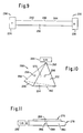
- Fig. 9 illustrates an acoustic logic device 230 according to the present invention which includes three ports and functions as a NOR gate.
- device 230 includes a resonant chamber 232 having transmitting transducer means 234 at one end and receiving transducer means 236 at the opposite end in a transmission configuration.
- the transmitter and receiver can be located at one end of chamber 232 with the opposite end being closed in a single pipe configuration.
- resonant chamber 232 can be defined by a cylindical bore or passage in a block or body of suitable material or, alternatively, it can be provided by a tubular structure.
- Three ports 240, 242 and 244 are provided in spaced relation along the length of chamber 232.
- the acoustic logic device 230 operates in the following manner. Transmitter 234 is tuned to the resonant frequency corresponding to all three ports 240, 242 and 244 being open. Accordingly, when all three ports are open the output signal provided by receiver 236 will exceed an electrically set threshold level. However, when any or all of the three ports are closed the output signal provided by receiver 236 will be below the threshold. Thus, the device 230 functions as a logical NOR gate. While the acoustic logic device 230 has been illustrated in a form including three ports, it can be in a form including a greater number of a ports, in which case it simply is tuned to all of the ports being open.
- Fig. 10 illustrates an acoustic logic device 250 according to the present invention which includes three ports and functions as an EXCLUSIVE OR gate.
- device 250 includes a non-planar port arrangement and a resonant chamber 252 defined by a pyramidal shaped structure having three walls 254, 256 and 258 meeting at one end in an apex 260 and joined at the opposite and by a base 262 thereby defining resonant chamber 252 in the interior thereof.
- a transmitter-receiver pair 264 is located at apex 260 and is in communication with resonant chamber 252.
- Three ports 266, 268 and 270 are provided, one on each of the walls 254, 256 and 258, respectively, in a non-planar arrangement as shown in Fig. 10.
- the acoustic logic device 250 operates in the following manner. If one of the ports is closed, there will be a particular resonant frequency of chamber 252 and if two of the ports are closed there will be a different resonant frequency for the chamber.
- the transmitter of pair 264 is tuned for one of the ports being closed. Accordingly, when one of the ports is closed the amplitude of the output signal provided by the receiver of pair 264 will exceed the electrically set threshold level resulting in a logical one output. However, when none of the ports is closed or when more than one of the ports is closed, the receiver output will be below the threshold level resulting in a logical zero. Thus, the device 250 functions as a logical EXCLUSIVE OR gate. While the acoustic logic device 250 has been illustrated in a form including three ports, it can be in a form including a greater number of ports, in which case it simply is tuned to one of the parts being closed.
- One exemplary use of the foregoing three port acoustic logic device is in sensing the proper position of a web 276 on the upper surface of a roller 278 shown in Fig. 11.
- the hollow interior 280 of roller 278 defines a resonant chamber and is closed at one end and provided with a transmitter-receiver pair 282 at the opposite end thereof.
- a pluraity of openings, the three designated 284, 286 and 288 in Fig. 11, are provided circumferentially around the mid-portion of roller 278 defining a plurality of ports in communication with resonant chamber 280.
- the transmitter of pair 282 is tuned to one of the ports being closed.
- 11 illustrates proper contact beteen web 276 and roller 278 thereby closing only one port with the result that the receiver of pair 282 provides a logical one output signal. If no web is present so that no ports are closed, or if the web were to break and hang up on roller 278 closing more than one port, this would be indicated by the receiver providing a logical zero output signal.
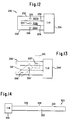
- Fig. 12 illustrates an acoustic logic device 290 according to the present invention which includes three ports and functions as an OR gate.
- Device 290 includes a resonant chamber defined within a hollow rectangular structure 292 closed at one end and in communication with a transmitter-receiver pair 294 at the opposite end thereof.
- a pair of internal walls 296, 298 are provided to define three resonant chamber portions 300a, 300b and 300c. Walls 296, 298 terminate inwardly at the end of structure 292 so that the three resonant chamber portions are in communication adjacent that end.
- Three ports 302, 304 and 306 are provided in a wall of structure 292 so as to be in communication with respective ones of the resonant chamber portions 300a, 300b and 300c as shown in Fig. 12.
- the transmitter of pair 294 is tuned to the resonant frequency corresponding to one of the ports being closed and to the resonant frequency corresponding to all of the ports being closed. This mode of operation involves the superposition of two input frequencies.
- the output signal provided by the receiver of pair 294 will exceed the electrically set threshold level resulting in a logical one output.
- the receiver output will be below the electrically set threshold level resulting in a logical zero.
- the device 290 functions as a logical OR gate. While the acoustic logic device 290 has been illustrated in a form including three ports, it can be in a form including a greater number of ports, in which case it simply is tuned to one of the ports being closed and all of the ports being closed.
- One illustrative use of the foregoing device is in sensing the presence of improperly oriented articles moving along a surface such as a conveyor belt.
- Device 290' shown in Fig. 13 would be located relative to the surface such that a properly oriented article such as 310 will close only one of the sensing ports, i.e. port 302'.
- the receiver of pair 294 therefore will provide a logical one output signal.
- An improperly oriented article such as 312 travelling along the surface will close two sensing ports, i.e., ports 304' and 306' whereupon the receiver of pair 294 provides a logical zero output signal.
- the sensing ports 302', 304' and 306' are in staggered relation and laterally separated by a distance determined by two conditions. First, the distance is greater than the width of the article. Second, the distance is set such that an improperly oriented article will close two ports as it moves along the surface.
- Fig. 14 illusrates an acoustic logic device 320 according to the present invention which includes three ports and functions as a NAND gate.
- Device 320 inclues a resonant chamber 322 closed at one end and provided with a transmitter-receiver pair 324 at the other end.
- Three ports 326, 328 and 330 are provided in spaced relation along the length of chamber 322.
- the transmitter of pair 324 feeds a signal which is a superposition of three resonant frequencies corresponding to all of the ports being open, two of the ports being open or one of the ports being open. When all of the ports are closed, no resonant frequency will be received and the threshold level will not be exceeded. Accordingly, the receiver will provide a logical zero output.
- the transmitter of pair 324 can be tuned to the resonant frequency corresponding to all of the ports being closed.
- the receiver threshold circuit is set such that it produces a logical zero.
- the device 320 functions as a logical NAND gate. While the acoustic logic device 320 has been illustrated in a form including three ports, it can be in a form including a greater number of ports, in which case it simply is tuned to all of the ports being closed providing a logical zero.
- a new and improved logic device employing acoustic means, in particular a digital logic device which utilizes the two state operation of acoustic sensing devices.
- the acoustic logic device according to the present invention is capable of implementing a variety of logic devices such as inverters and AND, NAND, OR and NOR gates, and the device of the present invention is relatively simple in structure and operation and is efficient and effective in operation. By having the passages and ports of relatively small cross-sectional size or area, very little air pressure, i.e. energy, is required in operation of the device.
Landscapes
- Physics & Mathematics (AREA)
- Engineering & Computer Science (AREA)
- Acoustics & Sound (AREA)
- Radar, Positioning & Navigation (AREA)
- Remote Sensing (AREA)
- Multimedia (AREA)
- Computer Networks & Wireless Communication (AREA)
- General Physics & Mathematics (AREA)
- Geophysics And Detection Of Objects (AREA)
- Electrostatic, Electromagnetic, Magneto- Strictive, And Variable-Resistance Transducers (AREA)
- Measurement Of Velocity Or Position Using Acoustic Or Ultrasonic Waves (AREA)
Claims (20)
- Akustische Logikvorrichtung mit einer Resonanzkammer (12), mindestens einem Port (16), der in der Kammer eine erste Resonanzfrequenz erzeugt, wenn der Port geschlossen ist, und eine zweite Resonanzfrequenz, wenn der Port offen ist, mit einem Sender (20), der der Kammer in Wirkverbindung zugeordnet und auf die erste oder die zweite Resonanzfrequenz abgestimmt ist, und mit einem Empfänger (22), der der Kammer (12) in Wirkverbindung zugeordnet ist und auf die darin entwickelten akustischen Signale reagiert, dadurch gekennzeichnet, daß der Empfänger (22) einen digitalen Logikausgang bildet.
- Akustische Logikvorrichtung nach Anspruch 1, dadurch gekennzeichnet, daß der Port (16) geschlossen und der Sender (20) auf die zweite Resonanzfrequenz derart abgestimmt ist, daß die Logikvorrichtung als Wechselrichter arbeitet.
- Akustische Logikvorrichtung nach Anspruch 1, dadurch gekennzeichnet, daß der Port (16) offen ist und der Sender (20) auf die erste Resonanzfrequenz derart abgestimmt ist, daß die Logikvorrichtung als Wechselrichter arbeitet.
- Akustische Logikvorrichtung, gekennzeichnet durch eine Resonanzkammer (60), mindestens zwei Ports (62, 64), die in der Kammer eine Vielzahl von Resonanzfrequenzen erzeugen in Abhängigkeit davon, ob die Ports alle offen, alle'geschlossen oder einige offen und die übrigen geschlossen sind, durch einen Empfänger (70), der der Kammer (60) in Wirkverbindung zugeordnet ist, auf die darin entwickelten akustischen Signale reagiert und einen digitalen Logikausgang bildet, und durch einen Sender (72), der der Kammer in Wirkverbindung zugeordnet und auf eine der Resonanfrequenzen derart abgestimmt ist, daß er den Typ der Logikvorrichtung bestimmt.
- Logikvorrichtung nach Anspruch 4 mit zwei Ports (62, 64), dadurch gekennzeichnet, daß der Sender auf die Resonanzfrequenz abgestimmt ist, die dem geschlossenen Zustand der beiden Ports entspricht, so daß die Logikvorrichtung als AND-Gate arbeitet.
- Logikvorrichtung nach Anspruch 4 mit zwei Ports (62, 64), dadurch gekennzeichnet, daß der Sender auf die Resonanzfrequenz abgestimmt ist, die dem offenen Zustand der beiden Ports entspricht, so daß die Logikvorrichtung als NOR-Gate arbeitet.
- Logikvorrichtung nach Anspruch 4 mit zwei Ports (62, 64), dadurch gekennzeichnet, daß der Sender auf die Resonanzfrequenz abgestimmt ist, die dem offenen Zustand des einen Ports und dem geschlossenen Zustand des anderen Ports entspricht, so daß die Logikvorrichtung als EXCLUSIVE-OR-Gate arbeitet.
- Logikvorrichtung nach Anspruch 4, dadurch gekennzeichnet, daß der Sender (72) in einem Modus arbeitet, bei dem zwei Eingangsfrequenzen übereinanderliegen, und daß der Sender auf eine erste Resonanzfrequenz abgestimmt ist, die dem geschlossenen Zustand des einen Ports (62, 64) und dem offenen Zustand des anderen Ports entspricht, und auf eine zweite Resonanzfrequenz, die dem geschlossenen Zustand beider Ports entspricht, so daß die Logikvorrichtung als OR-Gate arbeitet.
- Logikvorrichtung nach Anspruch 4, dadurch gekennzeichnet, daß der Sender (72) in einem Modus arbeitet, bei dem zwei Eingangsfrequenzen übereinanderliegen, und daß der Sender auf eine erste Resonanzfrequenz abgestimmt ist, die dem geschlossenen Zustand des einen Ports (62, 64) geschlossen und dem offenen Zustand des anderen Ports entspricht, und auf eine zweite Resonanzfrequenz, die dem offenen Zustand beider Ports entspricht, so daß die Logikvorrichtung als NAND-Gate arbeitet.
- Logikvorrichtung nach Anspruch 1 in Verbindung mit einem Gerät (160') zum Abtasten des Vorhandenseins oder Nichtvorhandenseins eines Gegenstandes (184, 186), dadurch gekennzeichnet, daß der Port (164') derart in Wirkverbindung mit dem Gegenstand bringbar ist, daß das Vorhandensein des Gegenstandes dadurch anzeigbar ist, daß der Gegenstand den Port schließt.
- Logikvorrichtung nach Anspruch 4 in Verbindung mit einem Gerät (160') zum Abtasten des Vorhandenseins oder Nichtvorhandenseins von Gegenständen (184, 186), dadurch gekennzeichnet, daß jeder Port (164',166') derart in Wirkverbindung mit einem Gegenstand bringbar ist, daß das Vorhandensein des Gegenstandes dadurch anzeigbar ist, daß der Gegenstand den Port schließt.
- Akustische Logikvorrichtung nach Anspruch 1, gekennzeichnet durch mindestens drei Ports (206, 208, 210), die in der Kammer (202) eine Vielzahl von Resonanzfrequenzen erzeugen in Abhängigkeit davon, ob die Ports alle offen oder alle geschlossen sind, ob ein Port geschlossen ist und die übrigen Ports offen sind oder ob ein Port offen ist und die übrigen Ports geschlossen sind, durch einen Empfänger (204), der der Kammer (202) in Wirkverbindung zugeordnet ist, auf die darin entwickelten akustischen Signale reagiert und einen digitalen Logikausgang bildet, und durch einen Sender (204), der der Kammer in Wirkverbindung zugeordnet und auf mindestens eine der Resonanzfrequenzen derart abgestimmt ist, daß er den Typ der Logikvorrichtung bestimmt.
- Logikvorrichtung nach Anspruch 12, dadurch gekennzeichnet, daß der Sender (204) auf die Resonanzfrequenz abgestimmt ist, die dem geschlossenen Zustand aller Ports entspricht, so daß die Vorrichtung als AND-Gate arbeitet.
- Logikvorrichtung nach Anspruch 13 in Verbindung mit einem Gerät (220) zum Abtasten der seitlichen Verschiebung eines sich entlang einer Bahn bewegenden Bandes bekannter Breite, dadurch gekennzeichnet, daß die äußersten Ports den Rändern des Bandes in Wirkverbindung derart zugeordnet sind, daß die beiden Ports vom Band abgedeckt sind, wenn das Band seitlich genau positioniert ist.
- Logikvorrichtung nach Anspruch 12, dadurch gekennzeichnet, daß der Sender (204) auf die Resonanzfrequenz abgestimmt ist, die dem offenen Zustand aller Ports entspricht, so daß die Vorrichtung als NOR-Gate arbeitet.
- Logikvorrichtung nach Anspruch 12, dadurch gekennzeichnet, daß der Sender (204) auf die Resonanzfrequenz abgestimmt ist, die dem geschlossenen Zustand eines der Ports entspricht, so daß die Vorrichtung als EXCLUSIVE-OR-Gate arbeitet.
- Logikvorrichtung nach Anspruch 16 in Verbindung mit einem Gerät zum Abtasten der genauen Position eines Bandes (276) auf einer Walze (278), dadurch gekennzeichnet, daß die Resonanzkammer innerhalb der Walze gebildet ist und die Ports auf der Umfangsfläche der Walze voneinander beabstandet sind.
- Logikvorrichtung nach Anspruch 12, dadurch gekennzeichnet, daß der Sender (204) in einem Modus arbeitet, bei dem zwei Eingangsfrequenzen übereinanderliegen, und daß der Sender (204) auf eine erste Resonanzfrequenz abgestimmt ist, die dem geschlossenen Zustand eines der Ports entspricht, und auf eine zweite Resonanzfrequenz, die dem geschlossenen Zustand aller Ports entspricht, so daß die Vorrichtung als OR Gate arbeitet.
- Logikvorrichtung nach Anspruch 18 in Verbindung mit einem Gerät (290') zum Abtasten des Vorhandenseins ungenau ausgerichteter, sich entlang einer Fläche bewegender Gegenstände (310, 312), dadurch gekennzeichnet, daß die Ports (302', 304', 306') derart bezüglich der Bewegungsrichtung der Gegenstände entlang der Fläche seitlich voneinander beabstandet sind, daß ein genau ausgerichteter Gegenstand nur einen Port und ein ungenau ausgerichteter Gegenstand zwei Ports schließt.
- Logikvorrichtung nach Anspruch 12, dadurch gekennzeichnet, daß der Sender in einem Modus arbeitet, bei dem drei Eingangsfrequenzen übereinanderliegen, und daß der Sender auf eine erste Resonanzfrequenz abgestimmt ist, die dem offenen Zustand aller Ports entspricht, auf eine zweite Resonanzfrequenz, die dem offenen Zustand zweier Ports entspricht, und auf eine dritte Resonanzfrequenz, die dem offenen Zustand eines Ports entspricht, so daß die Vorrichtung als NAND-Gate arbeitet.
Applications Claiming Priority (3)
| Application Number | Priority Date | Filing Date | Title |
|---|---|---|---|
| US07/706,915 US5138586A (en) | 1991-05-29 | 1991-05-29 | Acoustic logic circuits |
| US706915 | 1991-05-29 | ||
| PCT/US1992/004400 WO1992022055A1 (en) | 1991-05-29 | 1992-05-27 | Accoustic logic circuits |
Publications (2)
| Publication Number | Publication Date |
|---|---|
| EP0541777A1 EP0541777A1 (de) | 1993-05-19 |
| EP0541777B1 true EP0541777B1 (de) | 1998-12-23 |
Family
ID=24839604
Family Applications (1)
| Application Number | Title | Priority Date | Filing Date |
|---|---|---|---|
| EP92912828A Expired - Lifetime EP0541777B1 (de) | 1991-05-29 | 1992-05-27 | Akustische logische schaltungen |
Country Status (5)
| Country | Link |
|---|---|
| US (1) | US5138586A (de) |
| EP (1) | EP0541777B1 (de) |
| JP (1) | JPH05508988A (de) |
| DE (1) | DE69227981T2 (de) |
| WO (1) | WO1992022055A1 (de) |
Families Citing this family (3)
| Publication number | Priority date | Publication date | Assignee | Title |
|---|---|---|---|---|
| US8848486B1 (en) * | 2011-05-13 | 2014-09-30 | Cooper Technologies Company | Ultrasonic transmitter having adjustable output |
| CN102857216B (zh) * | 2012-08-25 | 2015-07-15 | 国家电网公司 | 谐振型异或门振荡集成系统 |
| CN110299129B (zh) * | 2019-05-27 | 2022-12-16 | 江苏大学 | 一种基于两元相控单元的宽频带亚波长声逻辑门 |
Family Cites Families (4)
| Publication number | Priority date | Publication date | Assignee | Title |
|---|---|---|---|---|
| US3665211A (en) * | 1970-01-11 | 1972-05-23 | North American Rockwell | Surface acoustic wave computer logic elements |
| US3694800A (en) * | 1970-04-24 | 1972-09-26 | Eastman Kodak Co | Acoustical gauge |
| US4494841A (en) * | 1983-09-12 | 1985-01-22 | Eastman Kodak Company | Acoustic transducers for acoustic position sensing apparatus |
| US4850232A (en) * | 1988-04-15 | 1989-07-25 | Eastman Kodak Company | System for measuring the dimensions of a workpiece |
-
1991
- 1991-05-29 US US07/706,915 patent/US5138586A/en not_active Expired - Fee Related
-
1992
- 1992-05-27 JP JP93500504A patent/JPH05508988A/ja active Pending
- 1992-05-27 WO PCT/US1992/004400 patent/WO1992022055A1/en not_active Ceased
- 1992-05-27 EP EP92912828A patent/EP0541777B1/de not_active Expired - Lifetime
- 1992-05-27 DE DE69227981T patent/DE69227981T2/de not_active Expired - Fee Related
Also Published As
| Publication number | Publication date |
|---|---|
| WO1992022055A1 (en) | 1992-12-10 |
| US5138586A (en) | 1992-08-11 |
| JPH05508988A (ja) | 1993-12-09 |
| DE69227981T2 (de) | 1999-07-08 |
| EP0541777A1 (de) | 1993-05-19 |
| DE69227981D1 (de) | 1999-02-04 |
Similar Documents
| Publication | Publication Date | Title |
|---|---|---|
| US4443731A (en) | Hybrid piezoelectric and magnetostrictive acoustic wave transducer | |
| EP0679907A2 (de) | Gerät zur Messung von kurzen Abständen mittels Ultraschall | |
| US5495766A (en) | Ultrasonic sensor | |
| US5161126A (en) | Acoustic flute web edge sensor | |
| CA2233852A1 (en) | Ultrasonic device for determining bone characteristics | |
| US4688423A (en) | System and process for measuring ultrasonic velocity | |
| JPS6013452B2 (ja) | 温度検知装置 | |
| US5138586A (en) | Acoustic logic circuits | |
| US4193027A (en) | Microwave moisture-profile gauge | |
| US2949772A (en) | Flowmeter | |
| GB2302946A (en) | Ultrasonic liquid level detector | |
| JPH0656309B2 (ja) | 超音波流量測定装置 | |
| US8878550B2 (en) | Sensor device for detecting an object in a detection area | |
| US4551825A (en) | Sonic ranging/detection system employing varied beamwidth | |
| US5771206A (en) | Elastic wave device for sensing a touch-position | |
| US4513404A (en) | Acoustic reflectometer for sheet feed sensing | |
| KR950006434A (ko) | 윈도우 외부표면 물체의 초음파 탐지장치 및 탐지장치가 장치된 윈도우 | |
| US5754498A (en) | System for measuring ultrasound transmission in materials | |
| JPH04362463A (ja) | 超音波送受信装置 | |
| WO1998000815A1 (en) | Apparatus for monitoring a document | |
| JPH0125346Y2 (de) | ||
| WO2006038312A1 (ja) | 無線応答装置および画像形成装置 | |
| JP2894011B2 (ja) | 電磁流量計検出器 | |
| GB2209218A (en) | An ultrasonic fluid flow meter with anti-fraud means | |
| FR2352286A1 (fr) | Perfectionnements aux debitmetres a ultra-sons fonctionnant par effet doppler, pour liquides charges de particules et notamment pour liquides organiques |
Legal Events
| Date | Code | Title | Description |
|---|---|---|---|
| PUAI | Public reference made under article 153(3) epc to a published international application that has entered the european phase |
Free format text: ORIGINAL CODE: 0009012 |
|
| 17P | Request for examination filed |
Effective date: 19930113 |
|
| AK | Designated contracting states |
Kind code of ref document: A1 Designated state(s): DE FR GB |
|
| 17Q | First examination report despatched |
Effective date: 19960717 |
|
| GRAG | Despatch of communication of intention to grant |
Free format text: ORIGINAL CODE: EPIDOS AGRA |
|
| GRAG | Despatch of communication of intention to grant |
Free format text: ORIGINAL CODE: EPIDOS AGRA |
|
| GRAH | Despatch of communication of intention to grant a patent |
Free format text: ORIGINAL CODE: EPIDOS IGRA |
|
| GRAH | Despatch of communication of intention to grant a patent |
Free format text: ORIGINAL CODE: EPIDOS IGRA |
|
| GRAA | (expected) grant |
Free format text: ORIGINAL CODE: 0009210 |
|
| AK | Designated contracting states |
Kind code of ref document: B1 Designated state(s): DE FR GB |
|
| REF | Corresponds to: |
Ref document number: 69227981 Country of ref document: DE Date of ref document: 19990204 |
|
| ET | Fr: translation filed | ||
| PLBE | No opposition filed within time limit |
Free format text: ORIGINAL CODE: 0009261 |
|
| STAA | Information on the status of an ep patent application or granted ep patent |
Free format text: STATUS: NO OPPOSITION FILED WITHIN TIME LIMIT |
|
| 26N | No opposition filed | ||
| PGFP | Annual fee paid to national office [announced via postgrant information from national office to epo] |
Ref country code: GB Payment date: 20010404 Year of fee payment: 10 |
|
| PGFP | Annual fee paid to national office [announced via postgrant information from national office to epo] |
Ref country code: FR Payment date: 20010503 Year of fee payment: 10 |
|
| PGFP | Annual fee paid to national office [announced via postgrant information from national office to epo] |
Ref country code: DE Payment date: 20010530 Year of fee payment: 10 |
|
| REG | Reference to a national code |
Ref country code: GB Ref legal event code: IF02 |
|
| PG25 | Lapsed in a contracting state [announced via postgrant information from national office to epo] |
Ref country code: GB Free format text: LAPSE BECAUSE OF NON-PAYMENT OF DUE FEES Effective date: 20020527 |
|
| PG25 | Lapsed in a contracting state [announced via postgrant information from national office to epo] |
Ref country code: DE Free format text: LAPSE BECAUSE OF NON-PAYMENT OF DUE FEES Effective date: 20021203 |
|
| GBPC | Gb: european patent ceased through non-payment of renewal fee |
Effective date: 20020527 |
|
| PG25 | Lapsed in a contracting state [announced via postgrant information from national office to epo] |
Ref country code: FR Free format text: LAPSE BECAUSE OF NON-PAYMENT OF DUE FEES Effective date: 20030131 |
|
| REG | Reference to a national code |
Ref country code: FR Ref legal event code: ST |