EP0541520B1 - Detector for detecting discontinuities in a pipe - Google Patents
Detector for detecting discontinuities in a pipe Download PDFInfo
- Publication number
- EP0541520B1 EP0541520B1 EP93300057A EP93300057A EP0541520B1 EP 0541520 B1 EP0541520 B1 EP 0541520B1 EP 93300057 A EP93300057 A EP 93300057A EP 93300057 A EP93300057 A EP 93300057A EP 0541520 B1 EP0541520 B1 EP 0541520B1
- Authority
- EP
- European Patent Office
- Prior art keywords
- sonde
- detector
- coils
- rod
- pipe
- Prior art date
- Legal status (The legal status is an assumption and is not a legal conclusion. Google has not performed a legal analysis and makes no representation as to the accuracy of the status listed.)
- Expired - Lifetime
Links
Images


Classifications
-
- G—PHYSICS
- G01—MEASURING; TESTING
- G01V—GEOPHYSICS; GRAVITATIONAL MEASUREMENTS; DETECTING MASSES OR OBJECTS; TAGS
- G01V3/00—Electric or magnetic prospecting or detecting; Measuring magnetic field characteristics of the earth, e.g. declination, deviation
- G01V3/08—Electric or magnetic prospecting or detecting; Measuring magnetic field characteristics of the earth, e.g. declination, deviation operating with magnetic or electric fields produced or modified by objects or geological structures or by detecting devices
- G01V3/10—Electric or magnetic prospecting or detecting; Measuring magnetic field characteristics of the earth, e.g. declination, deviation operating with magnetic or electric fields produced or modified by objects or geological structures or by detecting devices using induction coils
- G01V3/104—Electric or magnetic prospecting or detecting; Measuring magnetic field characteristics of the earth, e.g. declination, deviation operating with magnetic or electric fields produced or modified by objects or geological structures or by detecting devices using induction coils using several coupled or uncoupled coils
- G01V3/105—Electric or magnetic prospecting or detecting; Measuring magnetic field characteristics of the earth, e.g. declination, deviation operating with magnetic or electric fields produced or modified by objects or geological structures or by detecting devices using induction coils using several coupled or uncoupled coils forming directly coupled primary and secondary coils or loops
- G01V3/107—Electric or magnetic prospecting or detecting; Measuring magnetic field characteristics of the earth, e.g. declination, deviation operating with magnetic or electric fields produced or modified by objects or geological structures or by detecting devices using induction coils using several coupled or uncoupled coils forming directly coupled primary and secondary coils or loops using compensating coil or loop arrangements
Definitions
- the present invention relates to a detector for detecting discontinuities in a pipe as at joints.
- a present proposal for detecting joints in cast iron gas mains is to insert through the main a radio transmitter and to follow the transmitter above ground with a receiver. Reception of a signal indicates a joint.
- the object of the invention is to provide an improved detector particularly for detecting joints in gas mains, which alone gives indication of a joint.
- the coils may be arranged parallel with each other, their axes being spaced along the sonde.
- the coils are arranged parallel with each other, their axes being substantially co-axial.
- the drive current Whilst in the detector it is possible for the drive current to be a sinusoidal current, detection is facilitated if the drive current is a series of switched pulses and the receiving coil voltages are compared subsequent to each pulse.
- the current generating means together with the comparison means may be provided in a single unit with the coils
- the former means are provided remotely from the latter coils in the sonde but connected thereto by a cable.
- the cable is preferably arranged with a flexible rod.
- the sonde has an end spigot at which the flexible rod and the supply pipe are permanently attached and onto which is attached a protection tube, in which the flexible rod and the supply pipe extend.
- the flexible rod, supply pipe and protection tube may be accommodated when not in use on a coiling device.
- the cable may terminate at the hub of the coiling device at slip rings. However it is preferred that it continue as a flexible coil able to tolerate a limited number of twists corresponding to uncoiling of the full length of the flexible rod.
- the sonde in the detector is a circular cylindrical sonde with rounded ends and having a length appreciably greater - at least twice - than its diameter. This configuration allows the sonde to be pushed along the pipeline whilst resting at the bottom of its curvature and aligned with the length of the pipe.
- the comparison means may comprise a voltmeter with the receiving coils wired in series opposition.
- An audio alarm is preferably arranged to sound at a level of response above a threshold value.
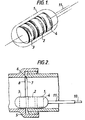
- the detector has a sonde 1 comprising a Tufnol (Trade Mark) former which is circular cylindrical with hemi-spherical ends.
- the former carries three coils 2,3,4 wrapped in protective glass reinforced plastics material.
- the sonde is typically 38mm in diameter and 100mm long. Its coils are all similar comprising 53 turns spreading 20mm axially and having a diameter of 33mm.
- the transmitting coil 2 axially in the centre of the sonde
- the receiving coils 3,4 are spaced axially at 200mm centre distances on either side of the transmitting coil. All the coils are co-axial. This configuration has been found to be suitable for detecting joints 5 in 150mm internal diameter cast iron pipes.
- the joint presents an annular space 6 of larger than 150mm diameter where the end 7 of one pipe received in the socket 8 of another pipe does not make perfect electrical contact with the root of the socket.
- the sonde lies at a joint with one receiving coil 3 at the joint space 6, the respective magnetic coupling between the two receiving coils and the pipe is unequal.
- the coils 2,3,4 are connected via a cable 10 inside a rod 11 to drive and detection circuitry within a control box 12.
- the circuitry is powered from a battery 13 of low voltage cells.
- a drive unit 14 applies a square current pulse of approximately 0.5 amperes for 50 sec to the transmitting coil 2 every 1 msec - that is at a frequency of 1 kHz with a mark space ratio of 20 to 1.
- the pulse induces magnetic field in the pipe at the sonde 1.
- the magnetic field is retained in the metal by eddy currents.
- the magnetic field from these eddy currents as they decay induces voltages in the receiving coils 3,4.
- the voltage induced in both is identical.
- the detection unit 15 includes a sampling voltmeter 16, enabled approximately 10 sec after each pulse of drive current, and a modulus unit 17 whose output is indicative of the difference in magnitude of the voltages induced in the coils 3,4. This output is applied for display to a voltmeter 18 in the form of a linear array of LEDs.
- the signal from the sampling voltmeter 16 is also applied to a high pass filter 19 and thence to a second modulus unit 17' and a threshold unit 20. When the voltage differences in the two receiving coils exceeds a determined threshold, an alarm 20' is sounded.
- the sonde 1 and rod 11 are introduced into the pipe via a clamp-on fitting 21 having a valve 22 and a seal 23.
- the seal 23 is initially assembled around the rod 11 with the sonde in a chamber 24 between the valve 22 and the seal 23.
- the sonde 1 is removable.
- the rod 11 has a Tufnol (Trade Mark) extension 30 bounded over the end of the glass fibre rod and having the outer diameter of a protective sheath 31 extending along the rod 11.
- Tufnol Trade Mark
- Four axially oriented, circumferentially spaced contact pads 32 are set in the extension 30 and are connected to the cable 10.
- This extension 30 extends into the centre of the sonde 1 and is secured thereto by a cross-pin 33 engaging in the forward hemi-spherical end of the sonde.
- the sonde has four spring biased contacts 34 which engage the pads 32. One pair of contacts is for the transmitting coil 2 and the other is for the receiving coils 3,4 wired in series opposition.
- the rod 11 When the seal 23 is tight, air is vented from the chamber 24 via a bleed 25 and the valve 22 is opened.
- the rod 11 is extended fully into the pipeline pushing the sonde past a number of joints.
- the rod which has limited flexibility being of glass reinforced plastics material, is unwound from a coil former 26.
- the cable 10 has a free length 27 extending from the hub 28 of the former to the control box 12. This free length is sufficient - typically 1 metre - to accommodate limited twisting as the few turns of the rod 11 are unwound.
- the rod is fully extended, it is withdrawn back towards the fitting 21. Every time the sonde passes a joint the audio alarm 20' is sounded. The exact location of the joint is found by moving the sonde back until the voltmeter displays a maximum reading. The position of the joint can be recorded by marking the rod at the seal 23. On withdrawal of the sonde, laying of the rod out on the ground over the pipe with the sonde at the entry point places the marks on the rod directly above the joints which they mark.
- the sonde 101 is permanently connected to its rod 102.
- the sonde comprises a generally circular cylindrical former 103 having three coils 104,105,106 set in corresponding grooves 107 in the circumferential surface of the former.
- the coils are protected by a glass reinforced plastics material wrapping 108.
- Connecting wires from the coils pass via drillings 109 to a bore 110 into one end of the former, for connection here with cable wires 111 within the rod 102.
- the rod 102 is a glass reinforced plastics rod having a central space occupied by the wires 111.
- the end of the rod is secured in the bore 110 by a pin 112 which passes through an end spigot 113 of the former and the edge of the rod - thereby securing it whilst missing the wires 111.
- a tubular connector 114 for a pipe 115 for supplying sealing compound.
- the pipe 115 and the rod 102 are both contained within an outer protective sheath 116 push-fitted onto the end spigot 112.
- the tubular connector 114 is in communication with a bore 115' within the former to a central void 117, around which the coil 104 extends.
- the coils are separated by spacing rims 118,119.
- Small diameter nozzle drillings 120 - typically 0.8mm in diameter - extend from the void 117 through the rims, whereby pressurised sealing compound from the pipe 115 can be sprayed via the drillings when for instance a joint in pipework is detected with the sonde.
- the void 117 is closed by an end cap 121 screwed into the end of the former opposite from its spigot 113.
- the cable wires are connected to control circuitry similar to that of the first embodiment and the pipe 115 is connected to means for applying pressurised sealing compound into the pipe 115.
- the sonde In use, the sonde is moved along inside a gas main to be sealed until a joint is detected and the circuitry alarms. The sonde is then positioned exactly on the joint in correspondence with a maximum voltmeter reading. The pressurised sealing compound is then applied down the pipe 115 and emerges as a jet from the nozzle drillings 120.
- the former has a plain circumference, to which the coil windings 202,203,204, in pre-wound form are applied. They are separated by spacing rings 205 and held in place by a glass reinforced plastics material wrapping 206. Wires from the winding extend in a surface groove 207 to the forward end of a spigot 208 into which they are led adjacent a bore 209 accommodating a rod 210 for connection to its wires.
- the former has a sealing compound void 211 and drillings 212 from this void through the coil spacing rings 205 for sealing compound spraying.
- a fourth embodiment of sonde 301 is generally planar, as shown in Figure 9. It, like the first embodiment, has no sealing compound spray arrangements. Its coils 302,303,304 are generally co-planar and slightly overlap. Their central axes 302',303',304' are axially spaced in the sonde.
Landscapes
- Life Sciences & Earth Sciences (AREA)
- Engineering & Computer Science (AREA)
- Physics & Mathematics (AREA)
- Remote Sensing (AREA)
- Geology (AREA)
- Environmental & Geological Engineering (AREA)
- Electromagnetism (AREA)
- General Life Sciences & Earth Sciences (AREA)
- General Physics & Mathematics (AREA)
- Geophysics (AREA)
- Geophysics And Detection Of Objects (AREA)
- Investigating Or Analyzing Materials By The Use Of Magnetic Means (AREA)
- Pipeline Systems (AREA)
Applications Claiming Priority (4)
| Application Number | Priority Date | Filing Date | Title |
|---|---|---|---|
| GB888807301A GB8807301D0 (en) | 1988-03-26 | 1988-03-26 | Detector |
| GB8807301 | 1988-03-26 | ||
| PCT/GB1989/000297 WO1989009417A1 (en) | 1988-03-26 | 1989-03-21 | Detector |
| EP89904816A EP0409882B1 (en) | 1988-03-26 | 1989-03-21 | Detector |
Related Parent Applications (1)
| Application Number | Title | Priority Date | Filing Date |
|---|---|---|---|
| EP89904816.9 Division | 1989-03-21 |
Publications (3)
| Publication Number | Publication Date |
|---|---|
| EP0541520A2 EP0541520A2 (en) | 1993-05-12 |
| EP0541520A3 EP0541520A3 (show.php) | 1994-04-13 |
| EP0541520B1 true EP0541520B1 (en) | 1996-05-15 |
Family
ID=10634214
Family Applications (2)
| Application Number | Title | Priority Date | Filing Date |
|---|---|---|---|
| EP93300057A Expired - Lifetime EP0541520B1 (en) | 1988-03-26 | 1989-03-21 | Detector for detecting discontinuities in a pipe |
| EP89904816A Expired - Lifetime EP0409882B1 (en) | 1988-03-26 | 1989-03-21 | Detector |
Family Applications After (1)
| Application Number | Title | Priority Date | Filing Date |
|---|---|---|---|
| EP89904816A Expired - Lifetime EP0409882B1 (en) | 1988-03-26 | 1989-03-21 | Detector |
Country Status (8)
| Country | Link |
|---|---|
| US (3) | US5302895A (show.php) |
| EP (2) | EP0541520B1 (show.php) |
| JP (2) | JP2842910B2 (show.php) |
| AU (1) | AU3426289A (show.php) |
| DE (2) | DE68915275T2 (show.php) |
| GB (2) | GB8807301D0 (show.php) |
| HK (1) | HK1007003A1 (show.php) |
| WO (1) | WO1989009417A1 (show.php) |
Families Citing this family (23)
| Publication number | Priority date | Publication date | Assignee | Title |
|---|---|---|---|---|
| GB8807301D0 (en) * | 1988-03-26 | 1988-04-27 | Philpot Electronics Ltd | Detector |
| GB2247062B (en) * | 1990-08-07 | 1994-05-18 | Alh Syst Ltd | Sealing of pipes |
| CA2076205C (en) * | 1992-08-14 | 1999-04-20 | Valentino S. Cecco | Differential transmit-receive eddy current probe incorporating bracelets of multi-coil units |
| FI973993L (fi) * | 1995-04-24 | 1997-12-17 | Goeran Larsson | Menetelmä ja laite ferromagneettisten kohteiden mittaamiseksi |
| US6291992B1 (en) * | 1996-07-12 | 2001-09-18 | Shell Oil Company | Eddy current inspection technique |
| DE19829999C1 (de) * | 1998-06-24 | 2000-01-13 | Mannesmann Ag | Verfahren und Meßgerät zur Detektierung der ordnungsgemäßen Einstecktiefe in einer Rohrpreßverbindung |
| AUPP813499A0 (en) * | 1999-01-13 | 1999-02-04 | Rock Solid Research Pty. Ltd. | A subsurface pipeline inspection probe |
| US6286542B1 (en) | 1999-05-14 | 2001-09-11 | Continental Industries, Inc. | Method and article of manufacture for inserting a locator wire into a subterranean, or otherwise concealed, pressurized plastic pipeline |
| US6755593B2 (en) * | 2001-01-22 | 2004-06-29 | Earth Tool Company, L.L.C. | Pipe replacement method and rotary impact mechanism for pipe bursting |
| US6792820B2 (en) * | 2001-03-29 | 2004-09-21 | Earth Tool Company, L.L.C. | Method and accessories for pipe replacement |
| FR2904694B1 (fr) * | 2006-08-03 | 2008-11-07 | Commissariat Energie Atomique | Procede et dispositif de controle par courants de foucault a fonctions emission/reception separees d'une piece electriquement conductrice |
| US7583073B2 (en) | 2007-07-19 | 2009-09-01 | Honeywell International Inc. | Core-less current sensor |
| US20110304336A1 (en) * | 2010-06-09 | 2011-12-15 | Consolidated Edison Company Of New York, Inc. | Device and Method For Locating A Conduit |
| US8558408B2 (en) | 2010-09-29 | 2013-10-15 | General Electric Company | System and method for providing redundant power to a device |
| US8278779B2 (en) | 2011-02-07 | 2012-10-02 | General Electric Company | System and method for providing redundant power to a device |
| US9057471B2 (en) | 2012-09-20 | 2015-06-16 | Jameson Llc | Method and device for tapping and tracing a conduit |
| DE102013209808A1 (de) | 2013-05-27 | 2014-11-27 | iCONTROLS k.s. | Induktiver Sensor |
| US20170081954A1 (en) * | 2015-09-23 | 2017-03-23 | Tesco Corporation | Pipe joint location detection system and method |
| US10330815B2 (en) | 2017-03-14 | 2019-06-25 | Saudi Arabian Oil Company | EMU impulse antenna for low frequency radio waves using giant dielectric and ferrite materials |
| US10317558B2 (en) * | 2017-03-14 | 2019-06-11 | Saudi Arabian Oil Company | EMU impulse antenna |
| US10416335B2 (en) * | 2017-03-14 | 2019-09-17 | Saudi Arabian Oil Company | EMU impulse antenna with controlled directionality and improved impedance matching |
| US10365393B2 (en) | 2017-11-07 | 2019-07-30 | Saudi Arabian Oil Company | Giant dielectric nanoparticles as high contrast agents for electromagnetic (EM) fluids imaging in an oil reservoir |
| CN111336410A (zh) * | 2020-04-20 | 2020-06-26 | 西南石油大学 | 一种导磁管柱冲蚀的实时在线检测装置及方法 |
Family Cites Families (13)
| Publication number | Priority date | Publication date | Assignee | Title |
|---|---|---|---|---|
| US2601248A (en) * | 1948-12-30 | 1952-06-24 | Standard Oil Co | Pipe line cleaner and locator |
| US3361960A (en) * | 1964-07-09 | 1968-01-02 | Atomic Energy Commission Usa | Pulsed nondestructive eddy current testing device using shielded specimen encircling coils |
| US3434046A (en) * | 1965-12-20 | 1969-03-18 | Halliburton Co | Electronic borehole casing collar locator |
| US3518533A (en) * | 1966-02-14 | 1970-06-30 | Essem Metotest Ab | Electroinductive sensing device with adjustable coil |
| US3786347A (en) * | 1972-12-21 | 1974-01-15 | Magnetic Analysis Corp | Apparatus for generating stable driving pulses for an eddy current test system |
| US3942105A (en) * | 1973-11-21 | 1976-03-02 | Bondarenko Oleg P | Non-contact inductive pickup for determining the interface between two media |
| IT1115746B (it) * | 1977-11-15 | 1986-02-03 | Siargas | Procedimento per la realizzazione di giunti a tenuta stagna in condotte interrate |
| US4325261A (en) * | 1979-10-09 | 1982-04-20 | Emerson Electric Co. | Pulsed DC constant current magnetic flowmeter |
| GB2098333B (en) * | 1981-05-08 | 1985-10-09 | Atomic Energy Authority Uk | Liquid level detector |
| JPS60161658U (ja) * | 1984-04-06 | 1985-10-26 | 株式会社東芝 | 車両用窓洗浄装置 |
| US4814702A (en) * | 1984-05-31 | 1989-03-21 | Westinghouse Electric Corp. | Process for accurately determining the position of the edges of support plates in steam generators |
| US4685516A (en) * | 1986-01-21 | 1987-08-11 | Atlantic Richfield Company | Apparatus for operating wireline tools in wellbores |
| GB8807301D0 (en) * | 1988-03-26 | 1988-04-27 | Philpot Electronics Ltd | Detector |
-
1988
- 1988-03-26 GB GB888807301A patent/GB8807301D0/en active Pending
-
1989
- 1989-03-21 EP EP93300057A patent/EP0541520B1/en not_active Expired - Lifetime
- 1989-03-21 AU AU34262/89A patent/AU3426289A/en not_active Abandoned
- 1989-03-21 HK HK98106159A patent/HK1007003A1/en not_active IP Right Cessation
- 1989-03-21 EP EP89904816A patent/EP0409882B1/en not_active Expired - Lifetime
- 1989-03-21 DE DE68915275T patent/DE68915275T2/de not_active Expired - Fee Related
- 1989-03-21 WO PCT/GB1989/000297 patent/WO1989009417A1/en not_active Ceased
- 1989-03-21 DE DE68926512T patent/DE68926512T2/de not_active Expired - Fee Related
- 1989-03-21 US US07/573,311 patent/US5302895A/en not_active Expired - Fee Related
- 1989-03-21 JP JP1504522A patent/JP2842910B2/ja not_active Expired - Fee Related
-
1990
- 1990-09-20 GB GB9020585A patent/GB2235302B/en not_active Expired - Lifetime
-
1992
- 1992-03-31 US US07/861,121 patent/US5367258A/en not_active Expired - Fee Related
-
1993
- 1993-11-17 US US08/153,648 patent/US5473246A/en not_active Expired - Lifetime
-
1996
- 1996-01-05 JP JP13796A patent/JP2834702B2/ja not_active Expired - Fee Related
Also Published As
| Publication number | Publication date |
|---|---|
| DE68926512T2 (de) | 1996-11-21 |
| EP0541520A3 (show.php) | 1994-04-13 |
| AU3426289A (en) | 1989-10-16 |
| DE68915275D1 (de) | 1994-06-16 |
| GB9020585D0 (en) | 1990-12-19 |
| JP2842910B2 (ja) | 1999-01-06 |
| JP2834702B2 (ja) | 1998-12-14 |
| DE68915275T2 (de) | 1994-09-01 |
| GB8807301D0 (en) | 1988-04-27 |
| US5367258A (en) | 1994-11-22 |
| US5473246A (en) | 1995-12-05 |
| GB2235302A (en) | 1991-02-27 |
| EP0409882B1 (en) | 1994-05-11 |
| WO1989009417A1 (en) | 1989-10-05 |
| HK1007004A1 (en) | 1999-03-26 |
| GB2235302B (en) | 1992-08-19 |
| EP0541520A2 (en) | 1993-05-12 |
| JPH08327606A (ja) | 1996-12-13 |
| HK1007003A1 (en) | 1999-03-26 |
| JPH03503682A (ja) | 1991-08-15 |
| DE68926512D1 (de) | 1996-06-20 |
| EP0409882A1 (en) | 1991-01-30 |
| US5302895A (en) | 1994-04-12 |
Similar Documents
| Publication | Publication Date | Title |
|---|---|---|
| EP0541520B1 (en) | Detector for detecting discontinuities in a pipe | |
| HK1007003B (en) | Detector | |
| US5530364A (en) | Cable partial discharge location pointer | |
| US6281685B1 (en) | Cable shield fault locator | |
| EP0678880B1 (en) | Inductive coupler for well tools | |
| US6573721B1 (en) | Time domain electromagnetic analysis and inspection system for conduits | |
| US6092558A (en) | Detectability of buried elongated objects such as pipes, ducts and conduits | |
| US4471651A (en) | Duct probe and dispensing apparatus therefor | |
| CN100410675C (zh) | 电力电缆故障的同步磁场定向定位法 | |
| US20160370166A1 (en) | Method and Apparatus for Metal Thickness Measurement in Pipes with a Focused Magnetic Field | |
| US7990138B2 (en) | Probe for analysis of a string of rods or tubes in a well | |
| US6489771B1 (en) | Passive external noise-canceling dynamic magnetic flux sensor for detecting the presence and direction of movement of a pig in a pipe | |
| JPS6013205A (ja) | 管体の腐食位置検出装置及びその検出方法 | |
| HK1007004B (en) | Detector for detecting discontinuities in a pipe | |
| US3284702A (en) | Apparatus for detecting coating holidays in metal pipeline walls utilizing helically wound pick-up coils and selfcontained power system | |
| EP0816838A1 (en) | Apparatus and method for well bore casing inspection | |
| US20120126804A1 (en) | Apparatus and method for detecting faulty concentric neutrals in a live power distribution cable | |
| KR101112216B1 (ko) | 매설 배관 탐사용 배선 조립체 및 매설 배관 탐사 방법 | |
| JP2566236B2 (ja) | パイプライン検査装置 | |
| US4527419A (en) | Sensor for underground duct probe | |
| CN106768506A (zh) | 一种用于铁磁性材料内力检测的磁通量传感器 | |
| GB2230612A (en) | Cable/rod measuring system | |
| CN206590695U (zh) | 一种地质物探电缆绕线器 | |
| RU2051391C1 (ru) | Зонд для скважинного определителя металла | |
| JPH03274486A (ja) | 磁気遮蔽導線およびそれを用いる物体の位置探査装置 |
Legal Events
| Date | Code | Title | Description |
|---|---|---|---|
| PUAI | Public reference made under article 153(3) epc to a published international application that has entered the european phase |
Free format text: ORIGINAL CODE: 0009012 |
|
| 17P | Request for examination filed |
Effective date: 19930120 |
|
| AC | Divisional application: reference to earlier application |
Ref document number: 409882 Country of ref document: EP |
|
| AK | Designated contracting states |
Kind code of ref document: A2 Designated state(s): BE DE FR GB IT NL |
|
| PUAL | Search report despatched |
Free format text: ORIGINAL CODE: 0009013 |
|
| AK | Designated contracting states |
Kind code of ref document: A3 Designated state(s): BE DE FR GB IT NL |
|
| 17Q | First examination report despatched |
Effective date: 19950406 |
|
| GRAH | Despatch of communication of intention to grant a patent |
Free format text: ORIGINAL CODE: EPIDOS IGRA |
|
| GRAA | (expected) grant |
Free format text: ORIGINAL CODE: 0009210 |
|
| AC | Divisional application: reference to earlier application |
Ref document number: 409882 Country of ref document: EP |
|
| AK | Designated contracting states |
Kind code of ref document: B1 Designated state(s): BE DE FR GB IT NL |
|
| REF | Corresponds to: |
Ref document number: 68926512 Country of ref document: DE Date of ref document: 19960620 |
|
| EN | Fr: translation not filed | ||
| ITF | It: translation for a ep patent filed | ||
| ET | Fr: translation filed | ||
| REG | Reference to a national code |
Ref country code: FR Ref legal event code: RN Ref country code: FR Ref legal event code: FC |
|
| REG | Reference to a national code |
Ref country code: FR Ref legal event code: RN Ref country code: FR Ref legal event code: FC |
|
| PLBE | No opposition filed within time limit |
Free format text: ORIGINAL CODE: 0009261 |
|
| 26N | No opposition filed | ||
| REG | Reference to a national code |
Ref country code: GB Ref legal event code: IF02 |
|
| BECH | Be: change of holder |
Owner name: *LATTICE INTELLECTUAL PROPERTY LTD Effective date: 20021209 |
|
| PGFP | Annual fee paid to national office [announced via postgrant information from national office to epo] |
Ref country code: FR Payment date: 20030211 Year of fee payment: 15 |
|
| PGFP | Annual fee paid to national office [announced via postgrant information from national office to epo] |
Ref country code: NL Payment date: 20030217 Year of fee payment: 15 |
|
| PGFP | Annual fee paid to national office [announced via postgrant information from national office to epo] |
Ref country code: DE Payment date: 20030225 Year of fee payment: 15 |
|
| PGFP | Annual fee paid to national office [announced via postgrant information from national office to epo] |
Ref country code: BE Payment date: 20030227 Year of fee payment: 15 |
|
| REG | Reference to a national code |
Ref country code: GB Ref legal event code: 732E |
|
| NLS | Nl: assignments of ep-patents |
Owner name: LATTICE INTELLECTUAL PROPERTY LIMITED |
|
| NLT1 | Nl: modifications of names registered in virtue of documents presented to the patent office pursuant to art. 16 a, paragraph 1 |
Owner name: TRANSCO PLC Owner name: BG TRANSCO PLC Owner name: BG PUBLIC LIMITED COMPANY |
|
| PGFP | Annual fee paid to national office [announced via postgrant information from national office to epo] |
Ref country code: GB Payment date: 20040212 Year of fee payment: 16 |
|
| PG25 | Lapsed in a contracting state [announced via postgrant information from national office to epo] |
Ref country code: BE Free format text: LAPSE BECAUSE OF NON-PAYMENT OF DUE FEES Effective date: 20040331 |
|
| BERE | Be: lapsed |
Owner name: *LATTICE INTELLECTUAL PROPERTY LTD Effective date: 20040331 |
|
| PG25 | Lapsed in a contracting state [announced via postgrant information from national office to epo] |
Ref country code: NL Free format text: LAPSE BECAUSE OF NON-PAYMENT OF DUE FEES Effective date: 20041001 Ref country code: DE Free format text: LAPSE BECAUSE OF NON-PAYMENT OF DUE FEES Effective date: 20041001 |
|
| PG25 | Lapsed in a contracting state [announced via postgrant information from national office to epo] |
Ref country code: FR Free format text: LAPSE BECAUSE OF NON-PAYMENT OF DUE FEES Effective date: 20041130 |
|
| NLV4 | Nl: lapsed or anulled due to non-payment of the annual fee |
Effective date: 20041001 |
|
| REG | Reference to a national code |
Ref country code: FR Ref legal event code: ST |
|
| PG25 | Lapsed in a contracting state [announced via postgrant information from national office to epo] |
Ref country code: IT Free format text: LAPSE BECAUSE OF NON-PAYMENT OF DUE FEES Effective date: 20050321 Ref country code: GB Free format text: LAPSE BECAUSE OF NON-PAYMENT OF DUE FEES Effective date: 20050321 |
|
| GBPC | Gb: european patent ceased through non-payment of renewal fee |
Effective date: 20050321 |