EP0409882B1 - Detector - Google Patents
Detector Download PDFInfo
- Publication number
- EP0409882B1 EP0409882B1 EP89904816A EP89904816A EP0409882B1 EP 0409882 B1 EP0409882 B1 EP 0409882B1 EP 89904816 A EP89904816 A EP 89904816A EP 89904816 A EP89904816 A EP 89904816A EP 0409882 B1 EP0409882 B1 EP 0409882B1
- Authority
- EP
- European Patent Office
- Prior art keywords
- sonde
- coils
- pipe
- receiving coils
- flexible rod
- Prior art date
- Legal status (The legal status is an assumption and is not a legal conclusion. Google has not performed a legal analysis and makes no representation as to the accuracy of the status listed.)
- Expired - Lifetime
Links
Images

Classifications
-
- G—PHYSICS
- G01—MEASURING; TESTING
- G01V—GEOPHYSICS; GRAVITATIONAL MEASUREMENTS; DETECTING MASSES OR OBJECTS; TAGS
- G01V3/00—Electric or magnetic prospecting or detecting; Measuring magnetic field characteristics of the earth, e.g. declination, deviation
- G01V3/08—Electric or magnetic prospecting or detecting; Measuring magnetic field characteristics of the earth, e.g. declination, deviation operating with magnetic or electric fields produced or modified by objects or geological structures or by detecting devices
- G01V3/10—Electric or magnetic prospecting or detecting; Measuring magnetic field characteristics of the earth, e.g. declination, deviation operating with magnetic or electric fields produced or modified by objects or geological structures or by detecting devices using induction coils
- G01V3/104—Electric or magnetic prospecting or detecting; Measuring magnetic field characteristics of the earth, e.g. declination, deviation operating with magnetic or electric fields produced or modified by objects or geological structures or by detecting devices using induction coils using several coupled or uncoupled coils
- G01V3/105—Electric or magnetic prospecting or detecting; Measuring magnetic field characteristics of the earth, e.g. declination, deviation operating with magnetic or electric fields produced or modified by objects or geological structures or by detecting devices using induction coils using several coupled or uncoupled coils forming directly coupled primary and secondary coils or loops
- G01V3/107—Electric or magnetic prospecting or detecting; Measuring magnetic field characteristics of the earth, e.g. declination, deviation operating with magnetic or electric fields produced or modified by objects or geological structures or by detecting devices using induction coils using several coupled or uncoupled coils forming directly coupled primary and secondary coils or loops using compensating coil or loop arrangements
Definitions
- LVDT linear variable-differential transformer
- apparatus for detecting a discontinuity in a pipe and for supplying a sealant to seal the discontinuity so detected, the apparatus comprising means for generating an electrical drive current, a sonde having a body with a transmitting coil to be subjected to the drive current and a pair of receiving coils spacedly arranged on respective opposite sides of the transmitting coil, whereby a magnetic field is set up in the pipe with the sonde adjacent to it on subjection of the transmitting coil to the said electrical current and the receiving coils have induced in them different voltages if the magnetic coupling from the pipe to one of the receiving coils differs from the magnetic coupling from the pipe to the other receiving coil due to a discontinuity in the medium; and means for comparing the voltages induced in the respective receiving coils, the sonde also having at least one sealing compound jetting nozzle for connection to a sealing compound supply pipe whereby on detecting the discontinuity the compound can be supplied to the at least one nozzle to seal the discontinuity, the sonde body having a
- the sonde has a removable end for cleaning the central chamber while suitably the coils are arranged parallel with each other, their axes being substantially co-axial.
- the drive current generating means may be adapted to generate a series of switched DC pulses and the induced voltage comparing means may be adapted to compare the said voltages subsequent to each pulse.
- the sonde 1 and rod 11 are introduced into the pipe via a clamp-on fitting 21 having a valve 22 and a seal 23.
- the seal 23 is initially assembled around the rod 11 with the sonde in a chamber 24 between the valve 22 and the seal 23.
- the sonde 1 is removable.
- the rod 11 has a Tufnol (Trade Mark) extension 30 bounded over the end of the glass fibre rod and having the outer diameter of a protective sheath 31 extending along the rod 11.
- Tufnol Trade Mark
- Four axially oriented, circumferentially spaced contact pads 32 are set in the extension 30 and are connected to the cable 10.
- This extension 30 extends into the centre of the sonde 1 and is secured thereto by a cross-pin 33 engaging in the forward hemi-spherical end of the sonde.
- the sonde has four spring biased contacts 34 which engage the pads 32. One pair of contacts is for the transmitting coil 2 and the other is for the receiving coils 3, 4 wired in series opposition.
- the rod is fully extended, it is withdrawn back towards the fitting 21. Every time the sonde passes a joint the audio alarm 20' is sounded. The exact location of the joint is found by moving the sonde back until the voltmeter displays a maximum reading. The position of the joint can be recorded by marking the rod at the seal 23. On withdrawal of the sonde, laying of the rod out on the ground over the pipe with the sonde at the entry point places the marks on the rod directly above the joints which they mark.
- the end of the rod is secured in the bore 110 by a pin 112 which passes through an end spigot 113 of the former and the edge of the rod - thereby securing it whilst missing the wires 111.
- a tubular connector 114 for a pipe 115 for supplying sealing compound.
- the pipe 115 and the rod 102 are both contained within an outer protective sheath 116 push-fitted onto the end spigot 112.
Abstract
Description
- The present invention relates to apparatus for detecting a discontinuity in a pipe and for supplying a sealant to seal the discontinuity so detected and is particularly though not exclusively, for detecting discontinuities inside metal pipes as at joints.
- It is desirable to be able to detect joints in gas mains since these can leak. This has become a particular problem since the replacement of manufactured gas by natural gas. The latter is much drier than the former, which can and does lead to joint packings drying out, shrinking and then leaking.
- A present proposal for detecting joints in cast iron gas mains is to insert through the main a radio transmitter and to follow the transmitter above ground with a receiver. Reception of a signal indicates a joint.
- US-A-3942105 relates to a non-contact inductive pickup for determining the interface between two media, the media having different specific density, different specific resistance and at least one of the media is electrically conductive and non-magnetic, the pickup comprising two open U-shaped magnetic circuits disposed parallel to each other and embraced by excitation and measuring windings.
- Product Engineering - April 21 1969 - page 160 - discloses a linear variable-differential transformer (LVDT) sensor for monitoring contours comprising three coils equally spaced along a cylindrical tube with a core of magnetically permeable material positioned co-axially inside the coil assembly, the core linking the magnetic flux between the coils.
- US-A-4178875 relates to an apparatus for sealing joints in underground pipelines, the apparatus comprising a carriage movable on rollers along the pipeline, means for detecting a joint between two pipes in the pipeline and a spray head in the form of a rotating nozzle mounted for rotation about the longitudinal axis of the carriage for spraying a sealant onto the joint after the position of the joint has been detected by the joint detecting means and movement of the carriage has stopped.
- The object of the invention is to provide an improved apparatus, for detecting joints in gas mains, which alone gives indication of a joint and which can also supply sealant to seal the joint so detected.
- According to the present invention, there is provided apparatus for detecting a discontinuity in a pipe and for supplying a sealant to seal the discontinuity so detected, the apparatus comprising means for generating an electrical drive current, a sonde having a body with a transmitting coil to be subjected to the drive current and a pair of receiving coils spacedly arranged on respective opposite sides of the transmitting coil, whereby a magnetic field is set up in the pipe with the sonde adjacent to it on subjection of the transmitting coil to the said electrical current and the receiving coils have induced in them different voltages if the magnetic coupling from the pipe to one of the receiving coils differs from the magnetic coupling from the pipe to the other receiving coil due to a discontinuity in the medium; and means for comparing the voltages induced in the respective receiving coils, the sonde also having at least one sealing compound jetting nozzle for connection to a sealing compound supply pipe whereby on detecting the discontinuity the compound can be supplied to the at least one nozzle to seal the discontinuity, the sonde body having a surface at which terminates the at least one nozzle which extends through the body.
- Preferably the sonde includes the connection to the supply pipe and suitably the sonde includes a plurality of nozzles for connection to the supply pipe. Conveniently the sonde has a central chamber for sealing compound in communication with the supply pipe and the at least one nozzle.
- Preferably the sonde has a removable end for cleaning the central chamber while suitably the coils are arranged parallel with each other, their axes being substantially co-axial.
- The sonde may be machined with circumferential grooves for the coils, the coils being spaced by rim members and being wound onto the sonde. The sonde may have a plain circumference and the coils may be prewound and assembled onto the sonde with coil spacing members.
- Preferably the coils are arranged parallel with each other, their axes being spaced along the sonde.
- The drive current generating means may be adapted to generate a series of switched DC pulses and the induced voltage comparing means may be adapted to compare the said voltages subsequent to each pulse.
- Preferably the apparatus includes a remote control unit having the current generating and the voltage comparing means and a cable connected between the sonde and the remote control unit, whereby the sonde is movable along the pipe independently of the control unit.
- Suitably the apparatus includes a flexible rod attached to the sonde and guiding the cable along the length of rod for movement of the sonde by manipulation of the remote end of the rod. Conveniently the cable is accommodated within the flexible rod.
- Preferably there is provided a coiling device on which the flexible rod can be coiled and the cable has a portion extending from a hub of the coiling device to the control unit, which portion is of such a length as to be able to tolerate a limited number of twists corresponding to uncoiling of the full length of the flexible rod.
- Suitably the sonde is permanently attached to the flexible rod and the three coils are permanently connected to the cable. Conveniently the sonde is detachable from the flexible rod and the three coils are disconnectible from the cable.
- The sonde may have an end spigot at which the flexible rod and the supply pipe are permanently attached and onto which is attached a protection tube into which the flexible rod and the supply pipe extend. The sonde may be generally circularly cylindrical with hemispherical ends with a length appreciably greater than its diameter.
- The receiving coils are preferably connected in series opposition and the induced voltage comparing means includes voltage measuring means.
- The voltage measuring means may be a sampling voltmeter and the induced voltage comparing means includes enabling means for enabling the sampling voltmeter a short period after each of the DC pulses, a modulus unit arranged to output the modulus of the output of the sampling voltmeter and a display voltmeter for displaying the output of the modulus unit as the modulus of the difference in voltage induced in the two, spaced receiving coils.
- The induced voltage comparing means may include a high pass filter connected to the sampling voltmeter, a second modulus unit connected to the high pass filter, a threshold unit connected to the second modulus unit and an alarm connected to the threshold unit, the arrangement being such that the alarm is triggered if the difference in voltage induced in the two, spaced receiving coils exceeds a predetermined threshold, indicative of a discontinuity in the pipe.
- To help understanding of the invention a specific embodiment thereof will now be described with reference to the accompanying drawings.
-
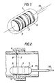
- Figure 1 is a diagrammatic perspective view of the sonde of a first embodiment of a detector;
- Figure 2 is a cross-sectional side view of a pipe joint with the coils in a sonde at the joint;
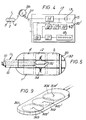
- Figure 3 is a diagrammatic side view of the detector;
- Figure 4 is a block diagram of electronic circuitry of the detector;
- Figure 5 is a cross-sectional view of the sonde;
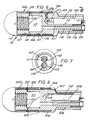
- Figure 6 is a cross-sectional side view of a sonde of a second embodiment;
- Figure 7 is a view in the direction of arrow VII in Figure 6;
- Figure 8 is a cross-sectional side view of a sonde in a third embodiment; and
- Figure 9 is a perspective view of a sonde of a fourth embodiment.
- Referring to Figures 1 to 5 of the drawings, the detector has a
sonde 1 comprising a Tufnol (Trade Mark) former which is circular cylindrical with hemi-spherical ends. The former carries threecoils coil 2 axially in the centre of the sonde, the receivingcoils joints 5 in 150mm internal diameter case iron pipes. Internally the joint presents anannular space 6 of larger than 150mm diameter where theend 7 of one pipe received in thesocket 8 of another pipe does not make perfect electrical contact with the root of the socket. When as shown in Figure 2, the sonde lies at a joint with one receivingcoil 3 at thejoint space 6, the respective magnetic coupling between the two receiving coils and the pipe is unequal. - The
coils cable 10 inside arod 11 to drive and detection circuitry within acontrol box 12. The circuitry is powered from abattery 13 of low voltage cells. Adrive unit 14 applies a square current pulse of approximately 0.5 amperes for 50 sec to the transmittingcoil 2 every 1 msec - this is at a frequency of 1 kHz with a mark space ratio of 20 to 1. The pulse induces magnetic field in the pipe at thesonde 1. When the pulse terminates, the magnetic field is retained in the metal by eddy currents. The magnetic field from these eddy currents as they decay induces voltages in thereceiving coils coils detection unit 15. If however thesonde 1 is at a joint, the detection unit will receive a signal in accordance with the imbalance of induced voltage. - The
detection unit 15 includes asampling voltmeter 16, enabled approximately 10 sec after each pulse of drive current, and amodulus unit 17 whose output is indicative of the difference in magnitude of the voltages induced in thecoils voltmeter 18 in the form of a linear array of LEDs. The signal from thesampling voltmeter 16 is also applied to a high pass filter 19 and thence to a second modulus unit 17' and a threshold unit 20. When the voltage differences in the two receiving coils exceeds a determined threshold, an alarm 20' is sounded. - The
sonde 1 androd 11 are introduced into the pipe via a clamp-on fitting 21 having a valve 22 and aseal 23. Theseal 23 is initially assembled around therod 11 with the sonde in achamber 24 between the valve 22 and theseal 23. - For assembly of the
rod 11 through theseal 23, thesonde 1 is removable. Therod 11 has a Tufnol (Trade Mark)extension 30 bounded over the end of the glass fibre rod and having the outer diameter of aprotective sheath 31 extending along therod 11. Four axially oriented, circumferentially spaced contact pads 32 are set in theextension 30 and are connected to thecable 10. Thisextension 30 extends into the centre of thesonde 1 and is secured thereto by a cross-pin 33 engaging in the forward hemi-spherical end of the sonde. The sonde has four springbiased contacts 34 which engage the pads 32. One pair of contacts is for the transmittingcoil 2 and the other is for the receiving coils 3, 4 wired in series opposition. - When the
seal 23 is tight, air is vented from thechamber 24 via ableed 25 and the valve 22 is opened. Therod 11 is extended fully into the pipeline pushing the sonde past a number of joints. In this operation, the rod, which has limited flexibility being of glass reinforced plastics material, is unwound from a coil former 26. Thecable 10 has afree length 27 extending from thehub 28 of the former to thecontrol box 12. This free length is sufficient - typically 1 metre - to accommodate limited twisting as the few turns of therod 11 are unwound. - Once the rod is fully extended, it is withdrawn back towards the fitting 21. Every time the sonde passes a joint the audio alarm 20' is sounded. The exact location of the joint is found by moving the sonde back until the voltmeter displays a maximum reading. The position of the joint can be recorded by marking the rod at the
seal 23. On withdrawal of the sonde, laying of the rod out on the ground over the pipe with the sonde at the entry point places the marks on the rod directly above the joints which they mark. - In the alternative embodiment of sonde shown in Figures 6 and 7, the
sonde 101 is permanently connected to itsrod 102. The sonde comprises a generally circular cylindrical former 103 having threecoils grooves 107 in the circumferential surface of the former. The coils are protected by a glass reinforced plastics material wrapping 108. Connecting wires from the coils pass via drillings 109 to abore 110 into one end of the former, for connection here with cable wires 111 within therod 102. Therod 102 is a glass reinforced plastics rod casing a central space occupied by the wires 111. The end of the rod is secured in thebore 110 by apin 112 which passes through anend spigot 113 of the former and the edge of the rod - thereby securing it whilst missing the wires 111. Also secured in theend spigot 113 is atubular connector 114 for apipe 115 for supplying sealing compound. Thepipe 115 and therod 102 are both contained within an outerprotective sheath 116 push-fitted onto theend spigot 112. - The
tubular connector 114 is in communication with a bore 115' within the former to acentral void 117, around which thecoil 104 extends. The coils are separated by spacingrims pipe 115 can be sprayed via the drillings when for instance a joint in pipework is detected with the sonde. Thevoid 117 is closed by an end cap 121 screwed into the end of the former opposite from itsspigot 113. - At their ends remote from the
sonde 101, the cable wires are connected to control circuitry similar to that of the first embodiment and thepipe 115 is connected to means for applying pressurised sealing compound into thepipe 115. - In use, the sonde is moved along inside a gas main to be sealed until a joint is detected and the circuitry alarms. The sonde is then positioned exactly on the joint in correspondence with a maximum voltmeter reading. The pressurised sealing compound is then applied down the
pipe 115 and emerges as a jet from thenozzle drillings 120. - In a third embodiment of sonde 201, shown in Figure 8, the former has a plain circumference, to which the
coil windings 202, 203, 204, in pre-wound form are applied. They are separated by spacingrings 205 and held in place by a glass reinforced plastics material wrapping 206. Wires from the winding extend in asurface groove 207 to the forward end of aspigot 208 into which they are led adjacent abore 209 accommodating arod 210 for connection to its wires. The former has a sealing compound void 211 anddrillings 212 from this void through the coil spacing rings 205 for sealing compound spraying. - A fourth embodiment of
sonde 301 is generally planar, as shown in Figure 9. It, like the first embodiment, has no sealing compound spray arrangements. Itscoils
Claims (22)
- Apparatus for detecting a discontinuity in a pipe and for supplying a sealant to seal the discontinuity so detected, the apparatus comprising means (14) for generating an electrical drive current; a sonde (101,201) having a body with a transmitting coil (104,202) to be subjected to the drive current, and a pair of receiving coils (106,106;203,204) spacedly arranged on respective opposite sides of the transmitting coil, whereby a magnetic field is set up in the pipe with the sonde adjacent to it on subjection of the transmitting coil to the said electrical current and the receiving coils have induced in them different voltages if the magnetic coupling from the pipe to one of the receiving coils differs from the magnetic coupling from the pipe to the other receiving coil due to a discontinuity in the pipe and means (16,17,17',18,19,20,21')for comparing the voltages induced in the respective receiving coils, the sonde body (101,201) also having at least one sealing compound jetting nozzle (120,212) for connection to a sealing compound supply pipe (115) whereby on detecting the discontinuity the compound can be supplied to the at least one nozzle to seal the discontinuity, characterised in that the sonde body (101,201) has a surface at which terminates the at least one nozzle (120,212) which extends through the body (101,201).
- Apparatus as claimed in claim 1, characterised in that the sonde includes the connection to the supply pipe (115).
- Apparatus as claimed in claim 1 or claim 2, characterised in that the sonde includes a plurality of nozzles (120,212) for connection to the supply pipe.
- Apparatus as claimed in any of the preceding claims, characterised in that the sonde has a central chamber (117) for sealing compound in communication with the supply pipe and the at least one nozzle.
- Apparatus as claimed in any of the preceding claims, characterised in that the sonde has a removable end (121) for cleaning of the central chamber.
- Apparatus as claimed in any of the preceding claims, characterised in that the coils are arranged parallel with each other, their axes being substantially co-axial.
- Apparatus as claimed in any of the preceding claims, characterised in that the sonde is machined with circumferential grooves for the coils, the coils being spaced by rim members (118,119;205) and being wound onto the sonde.
- Apparatus as claimed in any of the preceding claims, characterised in that the sonde has a plain circumference and the coils are prewound and assembled onto the sonde with coil spacing members (118,119;205).
- Apparatus as claimed in any of the preceding claims, characterised in that the coils are arranged parallel with each other, their axes being spaced along the sonde.
- Apparatus as claimed in any of the preceding claims, characterised in that the drive current generating means is adapted to generate a series of switched DC pulses and the induced voltage comparing means is adapted to compare the said voltages subsequent to each pulse.
- Apparatus as claimed in any of the preceding claims, characterised in that the current generating means and the voltage comparing means are provided as a single unit with the sonde.
- Apparatus as claimed in any of the preceding claims, characterised in including a remote control unit (15) having the current generating means and the voltage comparing means, and a cable (111) connected between the sonde and the remote control unit, whereby the sonde is movable along the pipe independently of the control unit.
- Apparatus as claimed in any of the preceding claims, characterised in including a flexible rod (102,210) attached to the sonde and guiding the cable along the length of the rod for movement of the sonde by manipulation of the remote end of the rod.
- Apparatus as claimed in claim 13, characterised in that the cable is accommodated within the flexible rod.
- Apparatus as claimed in claim 13 or claim 14, characterised in that there is provided a coiling device (26) on which the flexible rod can be coiled and the cable has a portion (27) extending from a hub of the coiling device to the control unit, which portion is of such a length as to be able to tolerate a limited number of twists corresponding to uncoiling of the full length of the flexible rod.
- Apparatus as claimed in any of claims 13 to 15, characterised in that the sonde is permanently attached to the flexible rod and the three coils are permanently connected to the cable.
- Apparatus as claimed in any of claims 13 to 16, characterised in that the sonde is detachable from the flexible rod and the three coils are disconnectible from the cable.
- Apparatus as claimed in any of claims 13 to 17, characterised in that the sonde has an end spigot (113,208) at which the flexible rod and the supply pipe are permanently attached and onto which is attached a protection tube (116), in which the flexible rod and the supply pipe extend.
- Apparatus as claimed in any of the preceding claims, characterised in that the sonde is generally circularly cylindrical with hemispherical ends, with a length appreciably greater than its diameter.
- Apparatus as claimed in any of the preceding claims, characterised in that the receiving coils are connected in series opposition and the induced voltage comparing means includes voltage measuring means.
- Apparatus as claimed in any of the preceding claims, characterised in that the voltage measuring means is a sampling voltmeter (16) and the induced voltage comparing means includes enabling means for enabling the sampling voltmeter a short period after each of the DC pulses, a modulus unit (17) arranged to output the modulus of the output of the sampling voltmeter, and a display voltmeter (18) for displaying the output of the modulus unit as the modulus of the difference in voltage induced in the two, spaced receiving coils.
- Apparatus as claimed in claim 21, characterised in that the induced voltage comparing means includes a high pass filter (19) connected to the sampling voltmeter, a second modulus unit (17') connected to the high pass filter, a threshold unit (20) connected to the second modulus unit and an alarm (20') connected to the threshold unit, the arrangement being such that the alarm is triggered if the difference in voltage induced in the two, spaced receiving coils exceeds a predetermined threshold, indicative of a discontinuity in the pipe.
Priority Applications (1)
| Application Number | Priority Date | Filing Date | Title |
|---|---|---|---|
| EP93300057A EP0541520B1 (en) | 1988-03-26 | 1989-03-21 | Detector for detecting discontinuities in a pipe |
Applications Claiming Priority (3)
| Application Number | Priority Date | Filing Date | Title |
|---|---|---|---|
| GB888807301A GB8807301D0 (en) | 1988-03-26 | 1988-03-26 | Detector |
| GB8807301 | 1988-03-26 | ||
| PCT/GB1989/000297 WO1989009417A1 (en) | 1988-03-26 | 1989-03-21 | Detector |
Related Child Applications (1)
| Application Number | Title | Priority Date | Filing Date |
|---|---|---|---|
| EP93300057.2 Division-Into | 1993-01-06 |
Publications (2)
| Publication Number | Publication Date |
|---|---|
| EP0409882A1 EP0409882A1 (en) | 1991-01-30 |
| EP0409882B1 true EP0409882B1 (en) | 1994-05-11 |
Family
ID=10634214
Family Applications (2)
| Application Number | Title | Priority Date | Filing Date |
|---|---|---|---|
| EP89904816A Expired - Lifetime EP0409882B1 (en) | 1988-03-26 | 1989-03-21 | Detector |
| EP93300057A Expired - Lifetime EP0541520B1 (en) | 1988-03-26 | 1989-03-21 | Detector for detecting discontinuities in a pipe |
Family Applications After (1)
| Application Number | Title | Priority Date | Filing Date |
|---|---|---|---|
| EP93300057A Expired - Lifetime EP0541520B1 (en) | 1988-03-26 | 1989-03-21 | Detector for detecting discontinuities in a pipe |
Country Status (8)
| Country | Link |
|---|---|
| US (3) | US5302895A (en) |
| EP (2) | EP0409882B1 (en) |
| JP (2) | JP2842910B2 (en) |
| AU (1) | AU3426289A (en) |
| DE (2) | DE68915275T2 (en) |
| GB (2) | GB8807301D0 (en) |
| HK (2) | HK1007004A1 (en) |
| WO (1) | WO1989009417A1 (en) |
Families Citing this family (24)
| Publication number | Priority date | Publication date | Assignee | Title |
|---|---|---|---|---|
| GB8807301D0 (en) * | 1988-03-26 | 1988-04-27 | Philpot Electronics Ltd | Detector |
| GB2247062B (en) * | 1990-08-07 | 1994-05-18 | Alh Syst Ltd | Sealing of pipes |
| CA2076205C (en) * | 1992-08-14 | 1999-04-20 | Valentino S. Cecco | Differential transmit-receive eddy current probe incorporating bracelets of multi-coil units |
| EP0823053A1 (en) * | 1995-04-24 | 1998-02-11 | Göran Larsson | Method and device for measuring ferro-magnetic objects |
| US6291992B1 (en) * | 1996-07-12 | 2001-09-18 | Shell Oil Company | Eddy current inspection technique |
| DE19829999C1 (en) * | 1998-06-24 | 2000-01-13 | Mannesmann Ag | Method and measuring device for detecting the correct insertion depth in a pipe press connection |
| AUPP813499A0 (en) | 1999-01-13 | 1999-02-04 | Rock Solid Research Pty. Ltd. | A subsurface pipeline inspection probe |
| US6286542B1 (en) | 1999-05-14 | 2001-09-11 | Continental Industries, Inc. | Method and article of manufacture for inserting a locator wire into a subterranean, or otherwise concealed, pressurized plastic pipeline |
| US6755593B2 (en) * | 2001-01-22 | 2004-06-29 | Earth Tool Company, L.L.C. | Pipe replacement method and rotary impact mechanism for pipe bursting |
| US6792820B2 (en) * | 2001-03-29 | 2004-09-21 | Earth Tool Company, L.L.C. | Method and accessories for pipe replacement |
| FR2904694B1 (en) * | 2006-08-03 | 2008-11-07 | Commissariat Energie Atomique | METHOD AND DEVICE FOR CHECKING FOR EXCELLENT TRANSMISSION / RECEPTION FOUCAULT CURRENTS OF AN ELECTRICALLY CONDUCTIVE PIECE |
| US7583073B2 (en) | 2007-07-19 | 2009-09-01 | Honeywell International Inc. | Core-less current sensor |
| US20110304336A1 (en) * | 2010-06-09 | 2011-12-15 | Consolidated Edison Company Of New York, Inc. | Device and Method For Locating A Conduit |
| US8558408B2 (en) | 2010-09-29 | 2013-10-15 | General Electric Company | System and method for providing redundant power to a device |
| US8278779B2 (en) | 2011-02-07 | 2012-10-02 | General Electric Company | System and method for providing redundant power to a device |
| US9057471B2 (en) | 2012-09-20 | 2015-06-16 | Jameson Llc | Method and device for tapping and tracing a conduit |
| DE102013209808A1 (en) | 2013-05-27 | 2014-11-27 | iCONTROLS k.s. | Inductive sensor |
| US20170081954A1 (en) * | 2015-09-23 | 2017-03-23 | Tesco Corporation | Pipe joint location detection system and method |
| US10416335B2 (en) * | 2017-03-14 | 2019-09-17 | Saudi Arabian Oil Company | EMU impulse antenna with controlled directionality and improved impedance matching |
| US10330815B2 (en) * | 2017-03-14 | 2019-06-25 | Saudi Arabian Oil Company | EMU impulse antenna for low frequency radio waves using giant dielectric and ferrite materials |
| US10317558B2 (en) * | 2017-03-14 | 2019-06-11 | Saudi Arabian Oil Company | EMU impulse antenna |
| CN107843934A (en) * | 2017-10-26 | 2018-03-27 | 中石化石油工程技术服务有限公司 | A kind of transient electromagnetic logging instrument magnetic probe |
| US10365393B2 (en) | 2017-11-07 | 2019-07-30 | Saudi Arabian Oil Company | Giant dielectric nanoparticles as high contrast agents for electromagnetic (EM) fluids imaging in an oil reservoir |
| CN111336410A (en) * | 2020-04-20 | 2020-06-26 | 西南石油大学 | Real-time online detection device and method for erosion of magnetic conduction pipe column |
Citations (3)
| Publication number | Priority date | Publication date | Assignee | Title |
|---|---|---|---|---|
| US3434046A (en) * | 1965-12-20 | 1969-03-18 | Halliburton Co | Electronic borehole casing collar locator |
| US4178875A (en) * | 1977-11-15 | 1979-12-18 | Siargas -- Societa' Italiana Assistenza Reti Gas S.p.A. | Apparatuses for producing tight joints or seals in underground pipelines |
| US4814702A (en) * | 1984-05-31 | 1989-03-21 | Westinghouse Electric Corp. | Process for accurately determining the position of the edges of support plates in steam generators |
Family Cites Families (10)
| Publication number | Priority date | Publication date | Assignee | Title |
|---|---|---|---|---|
| US2601248A (en) * | 1948-12-30 | 1952-06-24 | Standard Oil Co | Pipe line cleaner and locator |
| US3361960A (en) * | 1964-07-09 | 1968-01-02 | Atomic Energy Commission Usa | Pulsed nondestructive eddy current testing device using shielded specimen encircling coils |
| US3518533A (en) * | 1966-02-14 | 1970-06-30 | Essem Metotest Ab | Electroinductive sensing device with adjustable coil |
| US3786347A (en) * | 1972-12-21 | 1974-01-15 | Magnetic Analysis Corp | Apparatus for generating stable driving pulses for an eddy current test system |
| US3942105A (en) * | 1973-11-21 | 1976-03-02 | Bondarenko Oleg P | Non-contact inductive pickup for determining the interface between two media |
| US4325261A (en) * | 1979-10-09 | 1982-04-20 | Emerson Electric Co. | Pulsed DC constant current magnetic flowmeter |
| GB2098333B (en) * | 1981-05-08 | 1985-10-09 | Atomic Energy Authority Uk | Liquid level detector |
| JPS60161658U (en) * | 1984-04-06 | 1985-10-26 | 株式会社東芝 | Vehicle window cleaning equipment |
| US4685516A (en) * | 1986-01-21 | 1987-08-11 | Atlantic Richfield Company | Apparatus for operating wireline tools in wellbores |
| GB8807301D0 (en) * | 1988-03-26 | 1988-04-27 | Philpot Electronics Ltd | Detector |
-
1988
- 1988-03-26 GB GB888807301A patent/GB8807301D0/en active Pending
-
1989
- 1989-03-21 DE DE68915275T patent/DE68915275T2/en not_active Expired - Fee Related
- 1989-03-21 EP EP89904816A patent/EP0409882B1/en not_active Expired - Lifetime
- 1989-03-21 WO PCT/GB1989/000297 patent/WO1989009417A1/en active IP Right Grant
- 1989-03-21 DE DE68926512T patent/DE68926512T2/en not_active Expired - Fee Related
- 1989-03-21 JP JP1504522A patent/JP2842910B2/en not_active Expired - Fee Related
- 1989-03-21 EP EP93300057A patent/EP0541520B1/en not_active Expired - Lifetime
- 1989-03-21 AU AU34262/89A patent/AU3426289A/en not_active Abandoned
- 1989-03-21 US US07/573,311 patent/US5302895A/en not_active Expired - Fee Related
-
1990
- 1990-09-20 GB GB9020585A patent/GB2235302B/en not_active Expired - Lifetime
-
1992
- 1992-03-31 US US07/861,121 patent/US5367258A/en not_active Expired - Fee Related
-
1993
- 1993-11-17 US US08/153,648 patent/US5473246A/en not_active Expired - Lifetime
-
1996
- 1996-01-05 JP JP13796A patent/JP2834702B2/en not_active Expired - Fee Related
-
1998
- 1998-06-23 HK HK98106165A patent/HK1007004A1/en not_active IP Right Cessation
- 1998-06-23 HK HK98106159A patent/HK1007003A1/en not_active IP Right Cessation
Patent Citations (3)
| Publication number | Priority date | Publication date | Assignee | Title |
|---|---|---|---|---|
| US3434046A (en) * | 1965-12-20 | 1969-03-18 | Halliburton Co | Electronic borehole casing collar locator |
| US4178875A (en) * | 1977-11-15 | 1979-12-18 | Siargas -- Societa' Italiana Assistenza Reti Gas S.p.A. | Apparatuses for producing tight joints or seals in underground pipelines |
| US4814702A (en) * | 1984-05-31 | 1989-03-21 | Westinghouse Electric Corp. | Process for accurately determining the position of the edges of support plates in steam generators |
Also Published As
| Publication number | Publication date |
|---|---|
| JPH08327606A (en) | 1996-12-13 |
| DE68926512D1 (en) | 1996-06-20 |
| AU3426289A (en) | 1989-10-16 |
| DE68915275D1 (en) | 1994-06-16 |
| GB2235302A (en) | 1991-02-27 |
| HK1007004A1 (en) | 1999-03-26 |
| EP0541520A3 (en) | 1994-04-13 |
| GB8807301D0 (en) | 1988-04-27 |
| JPH03503682A (en) | 1991-08-15 |
| US5367258A (en) | 1994-11-22 |
| US5302895A (en) | 1994-04-12 |
| US5473246A (en) | 1995-12-05 |
| EP0541520B1 (en) | 1996-05-15 |
| GB2235302B (en) | 1992-08-19 |
| GB9020585D0 (en) | 1990-12-19 |
| WO1989009417A1 (en) | 1989-10-05 |
| DE68915275T2 (en) | 1994-09-01 |
| JP2842910B2 (en) | 1999-01-06 |
| JP2834702B2 (en) | 1998-12-14 |
| DE68926512T2 (en) | 1996-11-21 |
| EP0541520A2 (en) | 1993-05-12 |
| EP0409882A1 (en) | 1991-01-30 |
| HK1007003A1 (en) | 1999-03-26 |
Similar Documents
| Publication | Publication Date | Title |
|---|---|---|
| EP0409882B1 (en) | Detector | |
| CA2208994C (en) | Cable partial discharge location pointer | |
| US5914596A (en) | Coiled tubing inspection system | |
| US3483466A (en) | Pipeline inspection apparatus for detection of longitudinal defects | |
| AU595748B2 (en) | Magnetic flux leakage probe with radially offset coils for use in nondestructives testing of pipes and tubes | |
| US5479100A (en) | Method for detecting anomalies in pipes | |
| US3539915A (en) | Pipeline inspection apparatus for detection of longitudinal defects by flux leakage inspection of circumferential magnetic field | |
| AU654301B2 (en) | Transient electromagnetic inspection method and apparatus with moving sensors | |
| US6281685B1 (en) | Cable shield fault locator | |
| US4806863A (en) | Eddy current apparatus including cylindrical coil with flux concentrator for high resolution detection of flaws in conductive objects | |
| US5675251A (en) | Device and method for inspection of pipelines | |
| US9116016B2 (en) | Indicating system for a downhole apparatus and a method for locating a downhole apparatus | |
| US20160370166A1 (en) | Method and Apparatus for Metal Thickness Measurement in Pipes with a Focused Magnetic Field | |
| US6489771B1 (en) | Passive external noise-canceling dynamic magnetic flux sensor for detecting the presence and direction of movement of a pig in a pipe | |
| US7298131B2 (en) | Current sensors | |
| US3496457A (en) | Signal normalization apparatus for pipeline logging | |
| US3284702A (en) | Apparatus for detecting coating holidays in metal pipeline walls utilizing helically wound pick-up coils and selfcontained power system | |
| EP0816838A1 (en) | Apparatus and method for well bore casing inspection | |
| US4416057A (en) | Methods of testing the integrity of an electrical coil as it is wound | |
| US3363170A (en) | Pipe thickness detector utilizing a core structure which yields a narrow sensing field | |
| US4527419A (en) | Sensor for underground duct probe | |
| WO1996034279A1 (en) | Method and device for measuring ferro-magnetic objects | |
| GB2230612A (en) | Cable/rod measuring system | |
| JPH06103291B2 (en) | Pipe inspection device by remote field eddy current method | |
| JPH08278289A (en) | Flaw detection device and method for ferromagnetic tube |
Legal Events
| Date | Code | Title | Description |
|---|---|---|---|
| PUAI | Public reference made under article 153(3) epc to a published international application that has entered the european phase |
Free format text: ORIGINAL CODE: 0009012 |
|
| 17P | Request for examination filed |
Effective date: 19900924 |
|
| AK | Designated contracting states |
Kind code of ref document: A1 Designated state(s): BE DE FR GB IT NL |
|
| RAP1 | Party data changed (applicant data changed or rights of an application transferred) |
Owner name: BRITISH GAS PUBLIC LIMITED COMPANY |
|
| 17Q | First examination report despatched |
Effective date: 19911008 |
|
| GRAA | (expected) grant |
Free format text: ORIGINAL CODE: 0009210 |
|
| AK | Designated contracting states |
Kind code of ref document: B1 Designated state(s): BE DE FR GB IT NL |
|
| ITF | It: translation for a ep patent filed |
Owner name: JACOBACCI CASETTA & PERANI S.P.A. |
|
| REF | Corresponds to: |
Ref document number: 68915275 Country of ref document: DE Date of ref document: 19940616 |
|
| ET | Fr: translation filed | ||
| PLBE | No opposition filed within time limit |
Free format text: ORIGINAL CODE: 0009261 |
|
| STAA | Information on the status of an ep patent application or granted ep patent |
Free format text: STATUS: NO OPPOSITION FILED WITHIN TIME LIMIT |
|
| 26N | No opposition filed | ||
| REG | Reference to a national code |
Ref country code: GB Ref legal event code: IF02 |
|
| BECH | Be: change of holder |
Owner name: *LATTICE INTELLECTUAL PROPERTY LTD Effective date: 20021209 |
|
| PGFP | Annual fee paid to national office [announced via postgrant information from national office to epo] |
Ref country code: FR Payment date: 20030211 Year of fee payment: 15 |
|
| PGFP | Annual fee paid to national office [announced via postgrant information from national office to epo] |
Ref country code: NL Payment date: 20030217 Year of fee payment: 15 |
|
| PGFP | Annual fee paid to national office [announced via postgrant information from national office to epo] |
Ref country code: DE Payment date: 20030225 Year of fee payment: 15 |
|
| PGFP | Annual fee paid to national office [announced via postgrant information from national office to epo] |
Ref country code: BE Payment date: 20030227 Year of fee payment: 15 |
|
| REG | Reference to a national code |
Ref country code: GB Ref legal event code: 732E |
|
| NLT1 | Nl: modifications of names registered in virtue of documents presented to the patent office pursuant to art. 16 a, paragraph 1 |
Owner name: TRANSCO PLC Owner name: BG TRANSCO PLC Owner name: BG PUBLIC LIMITED COMPANY |
|
| NLS | Nl: assignments of ep-patents |
Owner name: LATTICE INTELLECTUAL PROPERTY LIMITED |
|
| PGFP | Annual fee paid to national office [announced via postgrant information from national office to epo] |
Ref country code: GB Payment date: 20040212 Year of fee payment: 16 |
|
| PG25 | Lapsed in a contracting state [announced via postgrant information from national office to epo] |
Ref country code: BE Free format text: LAPSE BECAUSE OF NON-PAYMENT OF DUE FEES Effective date: 20040331 |
|
| BERE | Be: lapsed |
Owner name: *LATTICE INTELLECTUAL PROPERTY LTD Effective date: 20040331 |
|
| PG25 | Lapsed in a contracting state [announced via postgrant information from national office to epo] |
Ref country code: NL Free format text: LAPSE BECAUSE OF NON-PAYMENT OF DUE FEES Effective date: 20041001 Ref country code: DE Free format text: LAPSE BECAUSE OF NON-PAYMENT OF DUE FEES Effective date: 20041001 |
|
| PG25 | Lapsed in a contracting state [announced via postgrant information from national office to epo] |
Ref country code: FR Free format text: LAPSE BECAUSE OF NON-PAYMENT OF DUE FEES Effective date: 20041130 |
|
| NLV4 | Nl: lapsed or anulled due to non-payment of the annual fee |
Effective date: 20041001 |
|
| REG | Reference to a national code |
Ref country code: FR Ref legal event code: ST |
|
| PG25 | Lapsed in a contracting state [announced via postgrant information from national office to epo] |
Ref country code: IT Free format text: LAPSE BECAUSE OF NON-PAYMENT OF DUE FEES;WARNING: LAPSES OF ITALIAN PATENTS WITH EFFECTIVE DATE BEFORE 2007 MAY HAVE OCCURRED AT ANY TIME BEFORE 2007. THE CORRECT EFFECTIVE DATE MAY BE DIFFERENT FROM THE ONE RECORDED. Effective date: 20050321 Ref country code: GB Free format text: LAPSE BECAUSE OF NON-PAYMENT OF DUE FEES Effective date: 20050321 |
|
| GBPC | Gb: european patent ceased through non-payment of renewal fee |
Effective date: 20050321 |