EP0541480A1 - Label detection for an electronic surveillance system - Google Patents
Label detection for an electronic surveillance system Download PDFInfo
- Publication number
- EP0541480A1 EP0541480A1 EP92810789A EP92810789A EP0541480A1 EP 0541480 A1 EP0541480 A1 EP 0541480A1 EP 92810789 A EP92810789 A EP 92810789A EP 92810789 A EP92810789 A EP 92810789A EP 0541480 A1 EP0541480 A1 EP 0541480A1
- Authority
- EP
- European Patent Office
- Prior art keywords
- frequency
- demodulator
- wobble
- signal
- generators
- Prior art date
- Legal status (The legal status is an assumption and is not a legal conclusion. Google has not performed a legal analysis and makes no representation as to the accuracy of the status listed.)
- Granted
Links
Images


Classifications
-
- G—PHYSICS
- G08—SIGNALLING
- G08B—SIGNALLING OR CALLING SYSTEMS; ORDER TELEGRAPHS; ALARM SYSTEMS
- G08B13/00—Burglar, theft or intruder alarms
- G08B13/22—Electrical actuation
- G08B13/24—Electrical actuation by interference with electromagnetic field distribution
- G08B13/2402—Electronic Article Surveillance [EAS], i.e. systems using tags for detecting removal of a tagged item from a secure area, e.g. tags for detecting shoplifting
- G08B13/2405—Electronic Article Surveillance [EAS], i.e. systems using tags for detecting removal of a tagged item from a secure area, e.g. tags for detecting shoplifting characterised by the tag technology used
- G08B13/2414—Electronic Article Surveillance [EAS], i.e. systems using tags for detecting removal of a tagged item from a secure area, e.g. tags for detecting shoplifting characterised by the tag technology used using inductive tags
-
- G—PHYSICS
- G08—SIGNALLING
- G08B—SIGNALLING OR CALLING SYSTEMS; ORDER TELEGRAPHS; ALARM SYSTEMS
- G08B13/00—Burglar, theft or intruder alarms
- G08B13/22—Electrical actuation
- G08B13/24—Electrical actuation by interference with electromagnetic field distribution
- G08B13/2402—Electronic Article Surveillance [EAS], i.e. systems using tags for detecting removal of a tagged item from a secure area, e.g. tags for detecting shoplifting
- G08B13/2465—Aspects related to the EAS system, e.g. system components other than tags
- G08B13/2468—Antenna in system and the related signal processing
- G08B13/2471—Antenna signal processing by receiver or emitter
-
- G—PHYSICS
- G08—SIGNALLING
- G08B—SIGNALLING OR CALLING SYSTEMS; ORDER TELEGRAPHS; ALARM SYSTEMS
- G08B13/00—Burglar, theft or intruder alarms
- G08B13/22—Electrical actuation
- G08B13/24—Electrical actuation by interference with electromagnetic field distribution
- G08B13/2402—Electronic Article Surveillance [EAS], i.e. systems using tags for detecting removal of a tagged item from a secure area, e.g. tags for detecting shoplifting
- G08B13/2465—Aspects related to the EAS system, e.g. system components other than tags
- G08B13/2468—Antenna in system and the related signal processing
- G08B13/2477—Antenna or antenna activator circuit
-
- G—PHYSICS
- G08—SIGNALLING
- G08B—SIGNALLING OR CALLING SYSTEMS; ORDER TELEGRAPHS; ALARM SYSTEMS
- G08B13/00—Burglar, theft or intruder alarms
- G08B13/22—Electrical actuation
- G08B13/24—Electrical actuation by interference with electromagnetic field distribution
- G08B13/2402—Electronic Article Surveillance [EAS], i.e. systems using tags for detecting removal of a tagged item from a secure area, e.g. tags for detecting shoplifting
- G08B13/2465—Aspects related to the EAS system, e.g. system components other than tags
- G08B13/2488—Timing issues, e.g. synchronising measures to avoid signal collision, with multiple emitters or a single emitter and receiver
Landscapes
- Physics & Mathematics (AREA)
- Engineering & Computer Science (AREA)
- Automation & Control Theory (AREA)
- Computer Security & Cryptography (AREA)
- Electromagnetism (AREA)
- General Physics & Mathematics (AREA)
- Signal Processing (AREA)
- Burglar Alarm Systems (AREA)
Abstract
Description
Die vorliegende Erfindung betrifft eine Vorrichtung zur Detektion von Etiketten, welche zur Diebstahlsicherung von Waren dienen und mit einem elektrischen Resonanzschaltkreis mit einer Resonanzfrequenz im MHz-Bereich versehen sind, wobei die Vorrichtung mehrere Paare von Sende- und Empfangsantennen umfasst, welche jeweils zu überwachende Durchgänge begrenzen, wobei von den Sendeantennen der Paare jeweils elektromagnetische Wellen abgestrahlt werden, deren Frequenz in Wobbelzyklen über die vorgegebene Resonanzfrequenz der Etiketten hinweg gewobbelt ist, wobei die Wobbelzyklen aller Paare miteinander synchronisiert sind und wobei an die Empfangsantenne jedes Paares eine, die Präsenz einer Etikette erkennende Empfangsschaltung angeschlossen ist.The present invention relates to a device for the detection of labels which are used for theft protection of goods and are provided with an electrical resonance circuit with a resonance frequency in the MHz range, the device comprising a plurality of pairs of transmitting and receiving antennas, each of which limits passages to be monitored , wherein each of the transmitting antennas of the pairs emits electromagnetic waves, the frequency of which is wobbled in wobble cycles beyond the predetermined resonance frequency of the labels, the wobble cycles of all pairs being synchronized with one another, and wherein to the receiving antenna of each pair a receiving circuit that detects the presence of a label connected.
Vorrichtungen dieser Art sind bekannt und vielfach im Einsatz, insbesondere in Supermärkten mit einer grösseren Anzahl von nebeneinander angeordneten Registrierkassen. Die Sende- und Empfangsantennen sind dabei in der Regel seitlich an den Registrierkassenboxen befestigt, wobei z.B. eine an einer ersten Registrierkassenbox befestigte Sendeantenne mit einer an der benachbarten Registrierkassenbox befestigten Empfangsantenne eines der genannten Paare von Sende- und Empfangsantennen bildet. Die über die Sendeantennen abgestrahlte Hochfrequenz wird zentral in einem HF-Generator erzeugt und über entsprechend teure Hochfrequenzkabel oder Glasfaserkabel zu den einzelnen Sendeantennen übertragen. Insbesondere bei einer grösseren Anzahl von Registrierkassen ist die Verkabelung mit den Hochfrequenzkabeln beziehungsweise den Glasfaserkabeln recht aufwendig.Devices of this type are known and widely used, particularly in supermarkets with a large number of cash registers arranged side by side. The transmitting and receiving antennas are generally attached to the side of the cash register boxes, with, for example, a transmitting antenna attached to a first cash register box with a receiving antenna attached to the adjacent cash register box forms one of the pairs of transmitting and receiving antennas mentioned. The radio frequency emitted via the transmission antennas is generated centrally in an HF generator and transmitted to the individual transmission antennas via correspondingly expensive radio frequency cables or fiber optic cables. Especially with a larger number of cash registers, the cabling with the high-frequency cables or the fiber optic cables is quite complex.
Es ist vor allem Aufgabe der vorliegenden Erfindung, eine Vorrichtung der eingangs genannten Art anzugeben, welche mit geringerem Aufwand installierbar ist.It is above all the object of the present invention to provide a device of the type mentioned at the outset which can be installed with less effort.
Diese sowie weitere Aufgaben werden gemäss der vorliegenden Erfindung gelöst durch eine Vorrichtung mit den im Patentanspruch 1 angegebenen Merkmalen.These and other objects are achieved according to the present invention by a device with the features specified in claim 1.
Erfindungsgemäss werden demnach die über die Sendeantennen als elektromagnetische Wellen abgestrahlten HF-Schwingungen nicht zentral, sondern von dezentralen, den Sendeantennen jeweils einzeln zugeordneten ersten HF-Generatoren erzeugt. Die Wobbelzyklen werden dabei unter Verwendung eines den HF-Generatoren zugeführten, in einer zentralen Einheit erzeugten Synchronisationssignals mit mindestens einer von der Resonanzfrequenz fR verschiedenen Frequenz miteinander synchronisiert.According to the invention, the RF vibrations emitted as electromagnetic waves via the transmitting antennas are not generated centrally, but rather by decentralized first RF generators, each of which is individually assigned to the transmitting antennas. The wobble cycles are synchronized with one another using a synchronization signal supplied to the HF generators and generated in a central unit with at least one frequency different from the resonance frequency f R.
Durch die dezentrale HF-Erzeugung entfällt mit Vorteil die aufwendige und sehr störanfällige Verkabelung mit den Hochfrequenzleitungen bzw. den Glasfaserkabeln. Es wird lediglich zur Synchronisation der einzelnen HF-Generatoren bzw. der Wobbelzyklen ein Signal mit mindestens einer Frequenz zentral erzeugt und zu den einzelnen HF-Generatoren übertragen.The decentralized HF generation advantageously eliminates the need for complex and very fault-prone cabling with the high-frequency lines or the fiber optic cables. A signal with at least one frequency is only generated centrally for the synchronization of the individual HF generators or the wobble cycles and transmitted to the individual HF generators.
Gemäss einer bevorzugten Ausgestaltung der Erfindung weist das Synchronisationssignal eine Trägerschwingung auf, auf welche mindestens noch die gewünschte Grundfrequenz der Wobbelzyklen, vorzugsweise jedoch zusätzlich noch Vielfache dieser Grundfrequenz (z.B. die 4-fache und die 32-fache Grundfrequenz) aufmoduliert ist/sind. Die Frequenz der Trägerschwingung kann dann mit Vorteil zur Festlegung der Frequenz der Wobbelzyklen und die auf die Trägerschwingung aufmodulierte/n Frequenz/en nach Demodulation zur Festlegung der Phase der Wobbelzyklen verwendet werden.According to a preferred embodiment of the invention, the synchronization signal has a carrier oscillation onto which at least the desired fundamental frequency of the wobble cycles, but preferably additionally multiples of this fundamental frequency (e.g. 4 times and 32 times the basic frequency) is / are modulated. The frequency of the carrier oscillation can then advantageously be used to determine the frequency of the wobble cycles and the frequency / s modulated onto the carrier oscillation after demodulation can be used to determine the phase of the wobble cycles.
Gemäss einer weiteren bevorzugten Ausgestaltung der Erfindung wird das zur Synchronisation benötigte Synchronisationssignal einfach ins elektrische Versorgungsnetz eingespeist, an das z.B. auch die Registrierkassen angeschlossen sind. Die wenigstens eine Frequenz des Synchronsationssignals liegt dabei im Langwellen(LW)-Bereich. Die LW-Signale weisen auf Leitungen einer elektrischen Gebäudeinstallation eine für den vorliegenden Zweck ausreichende Reichweite auf. Von den Postbehörden vieler Länder ist zur Signal- bzw. Datenübertragung über das elektrische Versorgungsnetz im LW-Bereich eigens ein Frequenzband freigegeben, wovon hier mit Vorteil Gebrauch gemacht wird.According to a further preferred embodiment of the invention, the synchronization signal required for synchronization is simply fed into the electrical supply network, to which e.g. the cash registers are also connected. The at least one frequency of the synchronization signal is in the long wave (LW) range. The LW signals on lines of an electrical building installation have a sufficient range for the present purpose. The postal authorities of many countries have specifically released a frequency band for signal and data transmission via the electrical supply network in the LW area, which is used here with advantage.
Zur Demodulation bzw. Diskriminierung der Etikettensignale in den dafür vorgesehenen Empfangsschaltungen wird üblicherweise ein Quadrierer am Eingang der Empfangsschaltungen verwendet, in welchem das von den Empfangsantennen empfangene Signal mit sich selbst multipliziert wird. Die Etikettendiskriminierung lässt sich entscheidend verbessern, wenn das empfangene, mit gewissen Störungen behaftete Signal statt mit sich selbst mit der reinen, der jeweiligen Sendeantenne zugeführten HF-Schwingung multipiziert wird. Zu diesem Zweck können die HF-Generatoren ausser an die Sendeantennen auch noch an die Empfangsschaltungen angeschlossen werden, welche mit den jeweils zugehörigen Empfangsantennen verbunden sind. Diese Möglichkeit ergibt sich mit Vorteil wiederum ohne grossen Verkabelungsaufwand als Folge der dezentralen Anordnung der HF-Generatoren.To demodulate or discriminate the label signals in the receiving circuits provided for this purpose, a square at the input of the receiving circuits is usually used, in which the signal received by the receiving antennas is multiplied by itself. Label discrimination can be significantly improved if the received signal, which is subject to certain interferences, is multiplied by the pure RF oscillation supplied to the respective transmitting antenna instead of itself. For this purpose, the HF generators can be connected not only to the transmitting antennas but also to the receiving circuits, which are connected to the associated receiving antennas. Again, this possibility advantageously arises without much Cabling effort as a result of the decentralized arrangement of the HF generators.
Sofern, wie eingangs erwähnt, die Sendeantennen bzw. Empfangsantennen seitlich an mehreren in Reihe angeordneten Registierkassenboxen montiert und die ihnen zugeordneten HF-Generatoren bzw. Empfangsschaltungen jeweils räumlich unmittelbar bei ihnen und damit auf unterschiedlichen Seiten der durch die Sende- und Empfangsantennen jeweils begrenzten Durchgänge zwischen den Registrierkassenboxen angeordnet sind, müssten, um die HF-Generatoren auch an die Empfangsschaltungen anschliessen zu können, HF-Leitungen die Durchgänge zwischen den Sendeantennen und ihren zugehörigen Empfangsantennen kreuzend verlegt werden. Um dies zu vermeiden, können gemäss einer weiteren bevorzugten Ausgestaltung der Erfindung die den Empfangsschaltungen zur Diskriminierung der Ettikettensignale jeweils zugeführten HF-Schwingungen von eigens dafür vorgesehenen, ebenfalls dezentralen, den Empfangsschaltungen jeweils einzeln, auch räumlich, zugeordneten zweiten HF-Generatoren erzeugt werden.Insofar as, as mentioned at the outset, the transmitting antennas or receiving antennas are mounted laterally on a plurality of cash register boxes arranged in series, and the RF generators or receiving circuits assigned to them are spatially directly next to them and therefore on different sides of the passages between the transmitting and receiving antennae the cash register boxes, in order to be able to connect the HF generators to the receiving circuits, HF lines would have to be laid crossing the passages between the transmitting antennas and their associated receiving antennas. In order to avoid this, according to a further preferred embodiment of the invention, the RF vibrations respectively supplied to the receiving circuits for discriminating the label signals can be generated by specially provided, also decentralized, second RF generators individually assigned to the receiving circuits, also spatially.
Selbstverständlich müssen dazu diese zweiten HF-Generatoren mit den ersten HF-Generatoren synchronisiert sein. Die Synchronität lässt sich aber sehr einfach wieder unter Verwendung des vorzugsweise über das Energieversorgungsnetz übertragenen, zur Synchronisierung der ersten HF-Generatoren untereinander sowieso schon vorhandenen Synchronisationssignals herstellen.Of course, these second RF generators must be synchronized with the first RF generators. However, the synchronicity can be established very easily again using the synchronization signal which is preferably transmitted via the power supply network and is already present in order to synchronize the first HF generators with one another.
Die zweiten HF-Generatoren können mit den jeweiligen Empfangsschaltungen, für die sie vorgesehen sind, sowie ggf. auch noch jeweils mit dem ersten HF-Generator für die an derselben Registrierkasse jeweils montierte Sendeantenne in einer baulichen Einheit integriert sein. Diese Baueinheit kann mit Vorteil z.B. irgendwo in der Registrierkassenbox untergebracht sein.The second RF generators can be integrated in a structural unit with the respective receiving circuits for which they are intended, and possibly also with the first RF generator for the transmitting antenna mounted on the same cash register. This unit can advantageously be accommodated somewhere in the cash register box, for example.
Gemäss einer weiteren Ausgestaltung der Erfindung wird die Frequenz der über die Sendeantennen abgestrahlten Signale sinusfömig über die vorgegebene Resonanzfrequenz der Etiketten gewobbelt. Dabei sind für die Etikettendetektion nur die annähernd linearen Abschnitte des Wobbelsinus zwischen den Maxima und Minima verwertbar, nicht jedoch die Zeitabschnitte um dessen Maxima und Minima herum. Diese Zeitabschnitte können jedoch sinnvoll genutzt werden, z.B. zum parallelen Deaktivieren von deaktivierbaren Etiketten. Werden während der Durchführung der Deaktivierung während der genannten Zeitabschnitte die Empfangsschaltungen ausser Funktion gesetzt oder zumindest unempfindlich geschaltet, dann können auch unerwünschte Beeinflussungen der Detektionssysteme durch die Deaktivierungssysteme und dadurch Fehlalarme vermieden werden. Die dazu wiederum erforderliche Synchronität zwischen den Detektions- und den Deaktivierungseinheiten kann in einfacher Weise ebenfalls wieder unter Verwendung des vorzugsweise auf dem Energieversorgungsnetz sowieso zur Verfügung stehenden Synchronisationssignals hergestellt werden.According to a further embodiment of the invention, the frequency of the signals emitted via the transmission antennas is swept sinusoidally over the predetermined resonance frequency of the labels. Only the approximately linear sections of the wobble sine between the maxima and minima can be used for the label detection, but not the time sections around its maxima and minima. However, these periods can be used sensibly, e.g. for the parallel deactivation of deactivatable labels. If the receiving circuits are deactivated or at least switched off during the deactivation during the mentioned time periods, then undesired influences on the detection systems by the deactivation systems and thereby false alarms can also be avoided. The synchronization between the detection and deactivation units required for this can also be restored in a simple manner using the synchronization signal which is preferably available anyway on the power supply network.
Schliesslich kann noch vorgesehen sein, dass die von der Sendeantenne jedes Paares abgestrahlten elektromagnetischen Wellen gegenüber den von der Sendeantenne jeden anderen Paares abgestrahlten elektromagnetischen Wellen frequenzversetzt über die vorgegebene Resonanzfrequenz der Etiketten hinweg gewobbelt werden und dass die Empfangsschaltung jedes paares schmalbandig jeweils nur auf der jeweiligen Sendefrequenz der zum gleichen Paar gehörigen Sendeantenne empfängt. Durch einen solchen Frequenzversatz werden, gleiche phasenlage der Wobbelzyklen aller Paare vorausgesetzt, eine weitestgehende Entkopplung der einzelnen Paare erreicht und gegenseitige Einflüsse der Paare untereinander praktisch eliminiert.Finally, it can also be provided that the electromagnetic waves emitted by the transmitting antenna of each pair are wobbled frequency-offset with respect to the electromagnetic waves emitted by the transmitting antenna of each other pair, and that the receiving circuit of each pair is narrowband only at the respective transmitting frequency receiving the same antenna belonging to the same pair. Such a frequency offset, provided the phases of the wobble cycles of all pairs are in the same phase, ensures that the individual pairs are largely decoupled and mutual influences between the pairs are practically eliminated.
In der Zeichnung zeigt:
- Fig. 1
- einen Ausschnitt aus einer längeren Reihe von Registrierkassenboxen eines Supermarktes mit einer daran installierten Vorrichtung gemäss der Erfindung,
- Fig. 2
- in einem Frequenz-Zeit-Diagramm drei gegeneinander frequenzverschobene Wobbelkurven,
- Fig. 3
- das Blockschaltbild eines Ausführungsbeispiels für eine Synchronisierschaltung -nach der Erfindung mit mehreren Demodulatoren D1,..,D5,
- Fig. 4
- das Blockschaltbild eines der Demodulatoren D1,..,D5 aus Fig.4,
- Fig 5
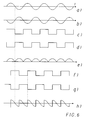
- schematisch ein Frequenzspektrum des Synchronisationssignals, und
- Fig. 6
- verschiedene in einem der Demodulatoren D1,..,D5 auftretende Signalformen.
- Fig. 1
- a section of a longer row of cash register boxes of a supermarket with a device according to the invention installed thereon,
- Fig. 2
- in a frequency-time diagram three wobble curves that are frequency-shifted against each other,
- Fig. 3
- the block diagram of an embodiment for a synchronization circuit - according to the invention with several demodulators D1, .., D5,
- Fig. 4
- the block diagram of one of the demodulators D1, .., D5 from Figure 4,
- Fig. 5
- schematically a frequency spectrum of the synchronization signal, and
- Fig. 6
- different signal forms occurring in one of the demodulators D1, .., D5.
Nachfolgend wird ein Ausführungsbeispiel der Erfindung unter Bezugnahme auf die beigefügten Zeichnungen erläutert.An exemplary embodiment of the invention is explained below with reference to the accompanying drawings.
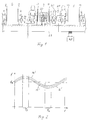
In Fig. 1 sind mit 1 - 4 lediglich vier einer grösseren Anzahl von nebeneinander angeordneten Registrierkassenboxen eines Supermarktes bezeichnet. Zwischen den Boxen sind Durchgänge 5 - 7 für die Kunden belassen, welche elektronisch auf Warendiebstahl überwacht werden. Zur elektronischen Diebstahlsüberwachung sind an den Waren Etiketten befestigt, welche mit einem elektronischen Resonanzkreis versehen sind. In Fig. 1 sind zwei mit solchen Resonanzetiketten 21 versehene Waren 20 beispielsweise dargestellt. Zur Detektion der Etiketten 21 sind beidseitig der Durchgänge seitlich an den Registrierkassenboxen Antennen 8 - 13 montiert. Die Antennen 8, 10 und 12 sind Sendeantennen, die Antennen 9, 11 und 13 Empfangsantennen.In Fig. 1, 1-4 only four of a larger number of cash register boxes of a supermarket arranged side by side are designated. Passages 5 - 7 are left between the boxes for the customers, which are electronic Theft of goods to be monitored. For electronic theft monitoring, labels are attached to the goods, which are provided with an electronic resonance circuit. 1 shows two
Die Sendeantennen werden angesteuert bzw. gespeist von ersten HF-Generatoren 14 - 16, welche HF-Schwingungen mit einer Frequenz von etwa 8,2 MHz erzeugen. Die Frequenz von 8,2 MHz, die in etwa der Soll-Resonanzfrequenz fR der zu detektierenden Etiketten entspricht, wird mit einer Wobbelfrequenz von etwa 85 Hz über einen Frequenzbereich von einigen hundert KHz gewobbelt (Fig. 2). In Fig. 2 sind die Wobbelkurven der in Fig. 1 dargestellten HF-Generatoren 14, 15 und 16 mit 14′, 15′ und 16′ bezeichnet.The transmit antennas are controlled or fed by first RF generators 14-16, which generate RF vibrations with a frequency of approximately 8.2 MHz. The frequency of 8.2 MHz, which corresponds approximately to the target resonance frequency f R of the labels to be detected, is wobbled with a wobble frequency of approximately 85 Hz over a frequency range of a few hundred kHz (FIG. 2). In Fig. 2 the wobble curves of the
Die einzelnen Wobbelkurven bzw. Wobbelzyklen und damit natürlich auch die sie erzeugenden, dezentral in den Registrierkassenboxen angeordneten HF-Generatoren 14 - 16 sind, wie auch anhand der Wobbelkurven von Fig. 2 zu erkennen ist, miteinander synchronisiert. Zur Synchronisation dient ein von einer Einheit 22 erzeugtes Synchronisationssignal mit einer Frequenz bzw. einem Frequenzspektrum im LW-Bereich. Dieses ist in eine Leitung 23 des die HF-Generatoren 14 - 16 sowie unter anderem auch die Registrierkassen mit elektrischer Energie versorgenden elektrischen Versorgungsnetzes eingekoppelt und wird über diese Leitung zu den genannten Elementen übertragen.The individual wobble curves or wobble cycles and thus of course also the RF generators 14-16 that generate them and are arranged decentrally in the cash register boxes are synchronized with one another, as can also be seen from the wobble curves of FIG. 2. A synchronization signal generated by a
Fig. 5 zeigt schematisch das Frequenzspektrum des Synchronisationssignals im LW-Bereich. Neben einer vorherrschenden Trägerfrequenz f₀ (z.B. 145 kHz) sind noch die Nebenfrequenzen f₀ +/-f₁ sowie f₀ +/- 4f₁ und f₀ +/- 32f₁ vorhanden. Die Frequenz f₁ (vorzugsweise 85 Hz) entspricht hierbei der Grundfrequenz der Wobbelzyklen von Fig. 2, ist also die Wobbelgrundfrequenz. Erzeugt wird das Frequenzspektrum von Fig. 5, indem auf eine Trägerschwingung mit der Frequenz f₀ die Frequenz f₁ sowie das 4- und vorzugsweise auch das 32-fache von f₁ aufmoduliert wird. In Fig. 5 sind (willkürlich) auch noch die unteren und oberen Bereichsgrenzen des von für die Datenübertragung auf dem elektrischen Versorgungsnetz postalisch zugelassenen Frequenzbandes eingezeichnet und mit fB u bzw.fB o bezeichnet.Fig. 5 shows schematically the frequency spectrum of the synchronization signal in the LW range. In addition to a prevailing carrier frequency f₀ (for example 145 kHz) there are also the secondary frequencies f₀ +/- f₁ and f₀ +/- 4f₁ and f₀ +/- 32f₁ available. The frequency f 1 (preferably 85 Hz) corresponds to the basic frequency of the wobble cycles of FIG. 2, so it is the basic wobble frequency. The frequency spectrum of FIG. 5 is generated by modulating onto a carrier oscillation with the frequency f 1, the frequency f 1 and 4 and preferably also 32 times f 1. 5 (arbitrarily) also shows the lower and upper range limits of the frequency band approved by post for data transmission on the electrical supply network and designated f B u and f B o , respectively.
Mit der Frequenz f₀ werden die Wobbelzyklen der einzelnen HF-Generatoren, z.B. unter Verwendung von sog. PLL-Schaltungen (PLL = Phase Locked Loop), miteinander frequenzmässig synchronisiert. Die Nebenfrequenzen dienen, nach Demodulation, zur Herstellung der gewünschten, übereinstimmenden Phasenlage der einzelnen Wobbelkurven. Das Blockschaltbild eines bevorzugten Ausführungsbeispiels für eine derartige Synchronisierschaltung, die jeweils einem der ersten HF-Generatoren (14-16) zugeordnet ist, ist in Fig. 4 wiedergegeben.The wobble cycles of the individual HF generators, e.g. using so-called PLL circuits (PLL = Phase Locked Loop), synchronized with each other in terms of frequency. After demodulation, the secondary frequencies serve to produce the desired, matching phase position of the individual wobble curves. The block diagram of a preferred exemplary embodiment for such a synchronization circuit, which is assigned to one of the first RF generators (14-16), is shown in FIG. 4.
Zentraler Bestandteil der Synchronisierschaltung ist ein spannungsgesteuerter Oszillator (VCO) 32, der eine Clockfrequenz (von z.B. 48 MHZ) als Mutterfrequenz für den jeweiligen HF-Generator erzeugt. Von der Clockfrequenz dieses VCO 32 werden durch als Frequenzteiler wirkende Zähler 33 und 34 jeweils die lokale Trägerfrequenz f₀ und die lokale Wobbelgrundfrequenz f₁ abgeleitet und phasenstarr gekoppelt bzw. in Phase gebracht mit den entsprechenden in der zentralen Einheit 22 erzeugten Signalen.A central component of the synchronization circuit is a voltage-controlled oscillator (VCO) 32, which generates a clock frequency (e.g. 48 MHz) as the mother frequency for the respective HF generator. From the clock frequency of this
Von der Netzleitung (23 in Fig. 1) her wird dazu die modulierte LW-Trägerschwingung über einen Koppeltransformator 29 und über einen nachgeschalteten (breitbandigen) LW-Verstärker 30 mit automatischer Verstärkungsregelung (AGC) auf die Eingänge zweier gleichartiger, steuerbarer Demodulatoren D1 und D2 gegeben, deren innerer Aufbau in Fig. 4 dargestellt ist. In den Demodulatoren D1 und D2 findet im Prinzip eine relativ zu einem am Steuereingang liegenden Steuersignal phasenempfindliche Gleichrichtung des Eingangssignals statt, die im Zusammenhang mit Fig. 4 und Fig. 6 später noch näher erläutert werden soll. Als Steuersignale für die beiden Demodulatoren D1 und D2 werden zwei in Quadratur stehende Ausgangssignale (Rechtecksignale) der lokalen Trägerfrequenz f₀ (140 kHz) aus dem ersten Zähler 33 verwendet.From the mains line (23 in FIG. 1), the modulated LW carrier oscillation for this is via a
Das Ausgangssignal des ersten Demodulators D1 wird in einem nachfolgenden Verstärker 31, der vorzugsweise eine Proportional/Integral(PI)-Charakteristik aufweist, verstärkt und zur Steuerung des VCO 32 verwendet. Die Blöcke D1, 31, 32 und 33 bilden damit die bereits erwähnte PLL-Regelschleife, die bewirkt, dass Frequenz und Phase der lokal und der zentral erzeugten Trägerschwingung gleich bzw. starr gekoppelt sind. Das Ausgangssignal des ersten Demodulators D1 ist im eingeschwungenen Zustand der Regelschleife ungefähr gleich null und die zentral erzeugte Trägerschwingung hat zum Steuersignal des ersten Demodulators D1 einen Phasenunterschied von +/- 90°.The output signal of the first demodulator D1 is amplified in a
Das Ausgangssignal des zweiten Demodulators D2 ist wegen der Quadraturbeziehung zwischen den Steuersignalen maximal, d.h., es ändert sich entsprechend der Einhüllenden der zentral erzeugten, modulierten Trägerschwingung und stellt somit das demodulierte, die Frequenzen f₁, 4f₁ und 32f₁ enthaltende Nutzsignal dar. Dieses Demodulationssignal, welches die in der Einheit 22 zentral erzeugte Wobbelgrundfrequenz enthält, wird nun dazu verwendet, die lokal mittels des zweiten Zählers 34 erzeugte Wobbelgrundfrequenz phasenmässig festzulegen. Hierzu wird wiederum eine Regelschleife verwendet, die in ihrer einfachsten Ausbaustufe einen dritten Demodulator D3, einen nachgeschalteten A/D-Wandler 36, einen Mikroprozessor 35 und einen Addierer 37 umfasst. Der Mikroprozessor 35 kann dabei ein bereits für andere Zwecke verwendeter Baustein sein, der die hier dargestellten Aufgaben zusätzlich übernimmt.The output signal of the second demodulator D2 is maximum because of the quadrature relationship between the control signals, that is, it changes according to the envelope of the centrally generated, modulated carrier oscillation and thus represents the demodulated, the frequencies f₁, 4f₁ and 32f₁ containing useful signal. This demodulation signal, which the wobble frequency generated centrally in the
Der zweite Zähler 34 hat einen Ausgang, an dem ein mehrere (z.B. 16) Bit breites Wort abgegeben wird und auf einen entsprechenden Eingang des Addierers 37 gelangt; gleiches gilt für den Ausgang des Addierers 37. Dasjenige Bit am Ausgang mit der höchsten Wichtung ist beim Addierer 37 in Fig. 3 mit MSB (Most Significant Bit) bezeichnet, dasjenige mit der drittgrössten Wichtung als MSB-2, dasjenige mit der sechstgrössten Wichtung als MSB-5. Durch das MSB steht die lokal erzeugte Wobbelgrundfrequenz zur Verfügung, durch MSB-2 die 2²-te, d.h., die 4-te Harmonische, und durch MSB-5 die 2⁵-te, d.h., die 32-te Harmonische der Grundfrequenz. Das Signal MSB aus dem Ausgang des Addierers 37 dient als Steuersignal des dritten Demodulators D3. Als Eingangssignal dient das Ausgangssignal des zweiten Demodulators, also die demodulierte Trägerschwingung.The
Die oben beschriebene Anordnung aus dem zweiten Zähler 34 und dem nachgeschalteten Addierer 37 gemäss Fig. 3 ist nur eine mögliche Ausführungsform. Es ist genauso gut auch denkbar, den Zähler 34 als ladbaren Zähler auszubilden, so dass die Addition direkt im Zähler 34 ausgeführt werden kann. Der Addierer 37 ist in diesem Fall natürlich überflüssig und der Ausgang des Mikroprozessors 35 wird direkt auf den Ladeeingang des Zählers 34 gegeben.The above-described arrangement of the
Sofern die Phasendifferenz zwischen dem MSB-Steuersignal und dem Demodulationssignal von einem Wert +/- 90° abweicht, ist das Ausgangsignal des dritten Demodulators D3 ungleich null. Dieses Ausgangssignal wird dann im nachfolgenden A/D-Wandler 36 in einen digitalen Wert umgewandelt, der vom Mikroprozessor 35 weiterverarbeitet wird. Der Mikroprozessor 35 gibt nach Massgabe des digitalen Eingangswertes eine inkrementelle Zahl aus, die im Addierer 37 zu den Zahlen aus dem Zähler 34 hinzuaddiert wird und damit das Rechtecksignal des MSB-Ausgangs in der Phase verschiebt. Diese Verschiebung erfolgt in der Regelschleife solange, bis MSB-Signal und Demodulationssignal eine feste Phasendifferenz von +/- 90° aufweisen.If the phase difference between the MSB control signal and the demodulation signal deviates from a value +/- 90 °, the output signal of the third demodulator D3 is not equal to zero. This output signal is then converted in the subsequent A /
Da diese Art der Phasenregelung noch relativ grob ist, werden bevorzugt Feinregelungen vorgenommen, indem nach der eben erläuterten Abstimmung auf der Wobbelgrundfrequenz nacheinander eine entsprechende Abstimmung auf der 4-ten bzw. 32-ten Harmonischen erfolgt. Dazu sind parallel zum dritten Demodulator ein vierter und fünfter Demodulator D4 bzw. D5 vorgesehen, die dasselbe Eingangssignal (Demodulationssignal) erhalten, als Steuersignal aber die Ausgangssignale MSB-2 bzw. MSB-5 des Addierers 37. Die Ausgänge der Demodulatoren D3 bis D5 können mittels des in Fig. 3 schematisch dargestellten Umschalters wahlweise, insbesondere nacheinander, auf den Eingang des A/D-Wandlers 36 geschaltet werden. Auf diese Weise lässt sich nacheinander in immer feiner werdender Abstimmung die Phase des MSB-Signals am Ausgang des Addierers 37 auf die Phase der zentral erzeugten Wobbelgrundfrequenz ausrichten. Das auf diese Weise an die zentral erzeugte Wobbelgrundfrequenz phasenstarr gekoppelte Wort am Ausgang des Addierers 37 kann im zugehörigen HF-Generator entsprechend weiterverwendet werden.Since this type of phase control is still relatively coarse, fine adjustments are preferably carried out in that, after the above-mentioned tuning on the basic sweep frequency, a corresponding tuning on the 4th or 32nd harmonic takes place in succession. For this purpose, a fourth and fifth demodulator D4 and D5 are provided in parallel to the third demodulator, which receive the same input signal (demodulation signal), but as a control signal, the output signals MSB-2 and MSB-5 of the
Der beispielhafte innere Aufbau eines der Demodulatoren D1,..,D5 (Dn)ist im Blockschaltbild in Fig. 4 wiedergegeben: Am gemeinsamen Signaleingang sind parallel ein normaler Verstärker 38 und ein Umkehrverstärker 39 (mit Spannungsteiler R1 = R2) angeschlossen. Deren Ausgänge sind über steuerbare, gleichartige Schalter 40 und 41 auf ein gemeinsames Tiefpassfilter 42 geschaltet. Der erste steuerbare Schalter 40 wird von dem am gemeinsamen Steuersignaleingang anstehenden Steuersignal direkt, der zweite Schalter 41 über einen Invertierer 43 angesteuert.The exemplary internal structure of one of the demodulators D1, .., D5 (Dn) is shown in the block diagram in FIG. 4: A
Die in der Schaltung nach Fig. 4 auftretenden Signale sind in Fig. 6 dargestellt: Wenn am Signaleingang des Demodulators Dn eine Sinusschwingung gemäss Fig. 6(b) ansteht, erscheint sie am Ausgang des Umkehrverstärkers 39 gemäss Fig. 6(a) invertiert, am Ausgang des Verstärkers 38 dagegen gemäss Fig. 6(b) normal. Wird nun auf den gemeinsamen Steuereingang des Demodulators Dn gemäss Fig. 6(c) ein Rechtecksignal gleicher Frequenz, aber um 180° verschobener Phase gegeben, werden beide steuerbaren Schalter 40, 41 abwechselnd gerade so geöffnet und geschlossen, dass sich am Eingang des Tiefpassfilters 42 das in Fig. 6(e) dargestellte Signal einstellt, welches charakteristisch ist für eine Vollweggleichrichtung des ursprünglichen Sinussignals. Ist dagegen das Rechteck-Steuersignal - wie in Fig. 6(f) bzw. (g) gezeigt - um 90° phasenverschoben, ergibt sich am Eingang des Tiefpassfilters 42 das in Fig. 6(h) dargestellte Signal, welches gleich grosse positive und negative Spannungsflächen aufweist und daher nach der Mittelung im Tiefpassfilter 42 null ergibt. Der in Fig. 6(a)-(e) gezeigte Fall ist beim zweiten Demodulator D2 gegeben, der in Fig. 6(f)-(h) gezeigte Fall bezieht sich auf die anderen Demodulatoren D1 und D3,..,D5.The signals occurring in the circuit according to FIG. 4 are shown in FIG. 6: If a sine wave according to FIG. 6 (b) is present at the signal input of the demodulator Dn, it appears 6 (a) inverted at the output of the reversing
Die Phasenlage liesse sich prinzipiell zwar auch durch ein "Aufeinander-Hören" der einzelnen Sender-Empfängerpaare einstellen, doch ist dieses Verfahren recht aufwendig auszuführen, zumindest solange die einzelnen Phasen noch sehr verschieden voneinander sind. Andererseits kann auf diese Weise, wenn die Phasenlage unter Auswertung der vorgenannten Nebenfrequenzen im wesentlichen bereits wie gewünscht eingestellt wurde, mit Vorteil noch ein Feinabgleich vorgenommen werden.In principle, the phase position could also be set by "listening to each other" of the individual transmitter-receiver pairs, but this method is very complex to carry out, at least as long as the individual phases are still very different from one another. On the other hand, if the phase position has already been essentially set as desired by evaluating the above-mentioned secondary frequencies, it is also advantageously possible to carry out a fine adjustment.
Sofern z.B. in einem Gebäude mehrere Verkaufsgeschäfte lokalisiert sind, welche unabhängig voneinander mit Warendiebstahlssicherungsanlagen der vorliegenden Art ausgerüstet sind, kann es zu Problemen mit der Synchronisation kommen, sofern alle diese Anlagen oder zumindest zwei unabhängig voneinander ein Synchronisationssignal mit der gleichen Frequenz ins elektrische Versorgungsnetz einspeisen.If, for example, several sales shops are located in a building, which are equipped independently of one another with anti-theft systems of the type in question, there may be problems with the synchronization if all these systems or at least two independently feed a synchronization signal with the same frequency into the electrical supply network.
Eine unerwünschte gegenseitige Beeinflussung der voneinander unabhängigen Anlagen kann jedoch dadurch einfach vermieden werden, indem die Frequenzen der Synchronisationssignale der verschiedenen Anlagen etwas verschieden voneinander gewählt werden. Dabei ist darauf zu achten, dass auch die Nebenfrequenzen sämtlich voneinander ausreichend verschieden sind.An undesirable mutual influence of the mutually independent systems can, however, simply be avoided by selecting the frequencies of the synchronization signals of the different systems somewhat differently from one another. It is important to ensure that the secondary frequencies are all sufficiently different from one another.
Bei dem Versuch, mit Etiketten 21 gesicherte Waren 20 unbezahlt durch einen der Durchgänge 5 - 7 zu schmuggeln (wie beispielsweise die in dem Einkaufswagen im Durchgang 6 liegende Ware 20), werden die Resonanzkreise dieser Etiketten durch die von den Sendeantennen abgestrahlten elektromagnetischen Wellen zum Schwingen angeregt. Der grösste Teil der mit dieser Schwingung verbundenen Schwingungsenergie wird von den Etiketten in Form elektromagnetischer Wellen wieder abgestrahlt. Neben den unmittelbar von den Sendeantennen abgestrahlten, können auch diese elektromagnetischen Wellen vermittels der Empfangsantennen empfangen werden. Die Empfangsantennen sind allerdings so ausgebildet (z.B. in zwei gegensinnig orientierte Teilflächen gleicher Grösse unterteilt), dass der grösste Teil der direkt von den Sendeantennen stammenden Hochfrequenz in der Antenne zur Fernfeldunterdrückung durch Selbstauslöschung eliminiert wird. Die an die Empfangsantennen angeschlossenen Empfangsschaltungen 17 - 19 dienen dazu, die recht schwachen Etikettensignale von der jedoch immer noch übrig bleibenden, direkt von den Sendeantennen stammenden Hochfrequenz sowie von Hintergrund etc. zu diskriminieren. Im Erfolgsfall wird durch die Empfangsschaltung ein Alarm ausgelöst. Zur Diskriminierung der Etikettensignale befindet sich unter anderem im Eingangsbereich der Empfangsschaltungen 17 - 19 ein Analogmultiplizierer bzw. Mischer (nicht dargestellt). In diesem werden die von den Empfangsantennen stammenden Signale jeweils mit einem Hochfrequenzsignal multipliziert, welches von für diesen Zweck eigens jeweils vorgesehen, zweiten HF-Generatoren erzeugt wird. Die zweiten HF-Generatoren erzeugen eine HF-Schwingung, die mit derjenigen übereinstimmt, mit welcher die zum jeweils gleichen Durchgang zugehörige Sendeantenne auf der anderen Seite des Durchgangs angesteuert wird. So entspricht beispielsweise die von dem zweiten HF-Generator 25 erzeugte HF-Schwingung derjenigen des ersten HF-Generators 15. Vermittels des über die Energieversorgungsleitung 23 übertragenen Synchronisationssignals können die zweiten HF-Generatoren mit ihren jeweils zugehörigen ersten HF-Generatoren synchronisiert werden.In an attempt to smuggle
Wie anhand von Fig. 2 zu erkennen ist, sind die sinusförmig gewählten Wobbelkurven gegeneinander auf der Frequenzachse etwas verschoben, wobei jedoch ihre gegenseitige Frequenzverschiebung so gering gegenüber dem Frequenzhub (Frequenzamplitude der Wobbelkurven) gewählt ist, dass alle Wobbelkurven (auch die der übrigen, ausserhalb des Ausschnitts von Fig. 1 lokalisierten ersten HF-Generatoren) noch mit ihren etwa linearen Abschnitten zwischen ihren Maxima und ihren Minima die Sollfrequenz fR schneiden. Vorzugsweise schneiden alle Wobbelkurven jedoch nicht lediglich die Sollfrequenz fR sondern ein gewisses Freuquenzband fR +/- df um die Sollfrequenz herum, um fertigungsbedingten Toleranzen der Resonanzfrequenz der Resonanzetiketten Rechnung zu tragen. Durch den gegenseitigen Frequenzversatz und die Synchronität der Wobbelkurven ist sichergestellt, dass die ersten HF-Generatoren zu jedem Zeitpunkt voneinander unterschiedliche Frequenzen erzeugen. Indem die Empfangsschaltungen 17 - 19 derart ausgebildet sind, dass sie genügend schmalbandig stets nur auf der jeweiligen Frequenz des zum gleichen Durchgang gehörenden ersten HF-Generators empfangen, wird in vorteilhafter Weise eine praktisch vollständige Entkopplung der einzelnen Paare von Sende-/Empfangseinheiten erreicht.As can be seen from FIG. 2, the sinusoidally selected wobble curves are slightly shifted relative to one another on the frequency axis, but their mutual frequency shift is so small compared to the frequency deviation (frequency amplitude of the wobble curves) that all wobble curves (including those of the others, outside) 1 section of localized first HF generators) still cut the target frequency f R with their approximately linear sections between their maxima and their minima. Preferably, however, all wobble curves do not only intersect the target frequency f R but a certain frequency band f R +/- df around the target frequency in order to take into account manufacturing-related tolerances of the resonance frequency of the resonance labels. The mutual frequency offset and the synchronicity of the wobble curves ensure that the first RF generators generate different frequencies at all times. Since the receiving circuits 17 - 19 are designed such that they always receive a sufficiently narrow band only at the respective frequency of the first RF generator belonging to the same pass, a practically complete decoupling of the individual pairs of transmitting / receiving units is advantageously achieved.
Mit 26 und 27 sind in Fig. 1 schliesslich noch ebenfalls in den Registrierkassenboxen angeordnete Deaktivatoren bezeichnet. Mittels dieser Deaktivatoren erfolgt eine Deaktivierung von an ordnungsgemäss bezahlten Waren befestigten Etiketten. Die Deaktivatoren können mittels des über die Leitung 23 übertragenen Synchronisationssignals mit den Empfangsschaltungen 17 - 19 synchronisiert sein. Indem die Empfangsschaltungen weiter während der in Fig. 2 mit TD bezeichneten, für die Diskriminierung von Etiketten sowieso nicht nutzbaren Zeitspannen inaktiviert werden, während die Deaktivatoren ausschliesslich während dieser Zeiten aktiv sind, wird eine ausgezeichnete Entkopplung auch der Etiketten-Detektion und der Etiketten-Deaktivierung erreicht.Finally, in FIG. 1, 26 and 27 also refer to deactivators arranged in the cash register boxes. These deactivators deactivate goods that have been properly paid for attached labels. The deactivators can be synchronized with the receiving circuits 17-19 by means of the synchronization signal transmitted via the
Die in den einzelnen Registrierkassenboxen angeordneten, vorbeschriebenen elektronischen Einheiten, können mit Vorteil bautechnisch jeweils in einer einzigen Baueinheit zusammengefasst sein.The above-described electronic units arranged in the individual cash register boxes can advantageously be combined in a single structural unit in terms of construction.
Es versteht sich, dass die vorliegende Erfindung nicht auf das erläuterte Beispiel beschränkt ist, bei dem die Sende- und die Empfangsantennen seitlich an Registrierkassenboxen montiert sind. Die Antennen könnten genausogut auch direkt am Ausgang freistehend und nicht in Verbindung mit Registrierkassenboxen montiert sein. In diesem Falle drängt es sich auf, die jeweils zwischen zwei Durchgängen vorhandenen Sende- und Empfangsantennen dicht beieinander anzuordnen und insbesondere sogar etwa in der gleichen Ebene. Denn optisch können die beieinander angeordneten Sende- und Empfangsantennen sogar wie ein einziges Bauteil ausgebildet sein. Durch eine geeignete geometrische Ausbildung der Antennen kann auch dafür gesorgt werden, dass der Empfang über die Empfangsantennen durch die. mittelbare Nähe der Sendeantennen nicht allzusehr beeinträchtigt wird. Die bereits erwähnte Verdrillung der Empfangsantennen ist hierfür ein Beispiel.It goes without saying that the present invention is not restricted to the example explained, in which the transmitting and receiving antennas are mounted laterally on cash register boxes. The antennas could just as well be free-standing directly at the exit and not installed in connection with cash register boxes. In this case, it is imperative to arrange the transmitting and receiving antennas between two passages in close proximity and in particular even in approximately the same plane. Because optically, the transmitting and receiving antennas arranged next to each other can even be designed as a single component. A suitable geometric design of the antennas can also ensure that the reception via the receiving antennas by the. indirect proximity of the transmitting antennas is not affected too much. The above-mentioned twisting of the receiving antennas is an example of this.
Claims (16)
Applications Claiming Priority (6)
| Application Number | Priority Date | Filing Date | Title |
|---|---|---|---|
| CH318591 | 1991-10-31 | ||
| CH3185/91 | 1991-10-31 | ||
| CH109892 | 1992-04-03 | ||
| CH1098/92 | 1992-04-03 | ||
| CH244692 | 1992-08-04 | ||
| CH2446/92 | 1992-08-04 |
Publications (2)
| Publication Number | Publication Date |
|---|---|
| EP0541480A1 true EP0541480A1 (en) | 1993-05-12 |
| EP0541480B1 EP0541480B1 (en) | 1996-07-24 |
Family
ID=27172693
Family Applications (1)
| Application Number | Title | Priority Date | Filing Date |
|---|---|---|---|
| EP92810789A Expired - Lifetime EP0541480B1 (en) | 1991-10-31 | 1992-10-15 | Label detection for an electronic surveillance system |
Country Status (5)
| Country | Link |
|---|---|
| US (1) | US5337040A (en) |
| EP (1) | EP0541480B1 (en) |
| JP (1) | JP2821068B2 (en) |
| AT (1) | ATE140813T1 (en) |
| DE (1) | DE59206809D1 (en) |
Cited By (1)
| Publication number | Priority date | Publication date | Assignee | Title |
|---|---|---|---|---|
| DE19722078A1 (en) * | 1997-05-27 | 1998-12-03 | Meto International Gmbh | System for the surveillance of electromagnetically secured articles in several surveillance zones |
Families Citing this family (15)
| Publication number | Priority date | Publication date | Assignee | Title |
|---|---|---|---|---|
| EP0589046B1 (en) * | 1992-02-18 | 1998-09-23 | Citizen Watch Co. Ltd. | Data carrier system |
| US5610584A (en) * | 1995-05-02 | 1997-03-11 | Schrade; Chester R. | Detection of goods on the bottom rack of a cart |
| US5874902A (en) * | 1996-07-29 | 1999-02-23 | International Business Machines Corporation | Radio frequency identification transponder with electronic circuit enabling/disabling capability |
| US5990791A (en) * | 1997-10-22 | 1999-11-23 | William B. Spargur | Anti-theft detection system |
| DE60236279D1 (en) * | 2001-02-08 | 2010-06-17 | Sensormatic Electronics Llc | AUTOMATIC WIRELESS SYNCHRONIZATION OF ELECTRONIC ARTICLE MONITORING SYSTEMS |
| US9201556B2 (en) | 2006-11-08 | 2015-12-01 | 3M Innovative Properties Company | Touch location sensing system and method employing sensor data fitting to a predefined curve |
| US8207944B2 (en) * | 2006-12-19 | 2012-06-26 | 3M Innovative Properties Company | Capacitance measuring circuit and method |
| US7956851B2 (en) * | 2006-12-20 | 2011-06-07 | 3M Innovative Properties Company | Self-tuning drive source employing input impedance phase detection |
| US20080149401A1 (en) * | 2006-12-20 | 2008-06-26 | 3M Innovative Properties Company | Untethered stylus employing separate communication channels |
| US8040329B2 (en) | 2006-12-20 | 2011-10-18 | 3M Innovative Properties Company | Frequency control circuit for tuning a resonant circuit of an untethered device |
| US8243049B2 (en) | 2006-12-20 | 2012-08-14 | 3M Innovative Properties Company | Untethered stylus employing low current power converter |
| US8134542B2 (en) | 2006-12-20 | 2012-03-13 | 3M Innovative Properties Company | Untethered stylus employing separate communication and power channels |
| US8089474B2 (en) * | 2006-12-28 | 2012-01-03 | 3M Innovative Properties Company | Location sensing system and method employing adaptive drive signal adjustment |
| US8040330B2 (en) * | 2006-12-28 | 2011-10-18 | 3M Innovative Properties Company | Untethered stylus empolying multiple reference frequency communication |
| US7787259B2 (en) * | 2006-12-28 | 2010-08-31 | 3M Innovative Properties Company | Magnetic shield for use in a location sensing system |
Citations (2)
| Publication number | Priority date | Publication date | Assignee | Title |
|---|---|---|---|---|
| US4356477A (en) * | 1980-09-30 | 1982-10-26 | Jan Vandebult | FM/AM Electronic security system |
| EP0316963A2 (en) * | 1988-04-05 | 1989-05-24 | Knogo Corporation | Multiple frequency theft detection system |
Family Cites Families (4)
| Publication number | Priority date | Publication date | Assignee | Title |
|---|---|---|---|---|
| US4309697A (en) * | 1980-10-02 | 1982-01-05 | Sensormatic Electronics Corporation | Magnetic surveillance system with odd-even harmonic and phase discrimination |
| US4623877A (en) * | 1983-06-30 | 1986-11-18 | Knogo Corporation | Method and apparatus for detection of targets in an interrogation zone |
| DK161227C (en) * | 1986-01-27 | 1991-11-25 | Antonson Security Denmark Aps | DEVICE DETECTOR SYNCHRONIZER DEVICE |
| NL9000186A (en) * | 1990-01-25 | 1991-08-16 | Nedap Nv | DEACTIVATOR. |
-
1992
- 1992-10-13 US US07/959,991 patent/US5337040A/en not_active Expired - Fee Related
- 1992-10-15 JP JP4277253A patent/JP2821068B2/en not_active Expired - Fee Related
- 1992-10-15 AT AT92810789T patent/ATE140813T1/en not_active IP Right Cessation
- 1992-10-15 EP EP92810789A patent/EP0541480B1/en not_active Expired - Lifetime
- 1992-10-15 DE DE59206809T patent/DE59206809D1/en not_active Expired - Fee Related
Patent Citations (2)
| Publication number | Priority date | Publication date | Assignee | Title |
|---|---|---|---|---|
| US4356477A (en) * | 1980-09-30 | 1982-10-26 | Jan Vandebult | FM/AM Electronic security system |
| EP0316963A2 (en) * | 1988-04-05 | 1989-05-24 | Knogo Corporation | Multiple frequency theft detection system |
Cited By (1)
| Publication number | Priority date | Publication date | Assignee | Title |
|---|---|---|---|---|
| DE19722078A1 (en) * | 1997-05-27 | 1998-12-03 | Meto International Gmbh | System for the surveillance of electromagnetically secured articles in several surveillance zones |
Also Published As
| Publication number | Publication date |
|---|---|
| JP2821068B2 (en) | 1998-11-05 |
| EP0541480B1 (en) | 1996-07-24 |
| DE59206809D1 (en) | 1996-08-29 |
| US5337040A (en) | 1994-08-09 |
| JPH0620165A (en) | 1994-01-28 |
| ATE140813T1 (en) | 1996-08-15 |
Similar Documents
| Publication | Publication Date | Title |
|---|---|---|
| EP0541480B1 (en) | Label detection for an electronic surveillance system | |
| DE69636999T2 (en) | ANTENNA ARRANGEMENT FOR GOODS MONITORING SYSTEM WITH IMPROVED DEMAND DISTRIBUTION | |
| DE2331328C2 (en) | ||
| DE60035982T2 (en) | SYSTEM FOR DETECTING, MEASURING AND DEACTIVATING A RESONANCE CIRCUIT USING A NUMERICALLY CONTROLLED OSCILLATOR | |
| DE3715387C2 (en) | ||
| DE3235434C2 (en) | Method and device for detecting goods when they are transported out of a surveillance zone | |
| DE809568C (en) | Device for scanning a predetermined space with a character beam | |
| DE1766065B2 (en) | Frequency converting responder with non-linear impedance element and monitoring system for use therewith | |
| DE2920263A1 (en) | DETECTION SYSTEM | |
| DE4023982A1 (en) | SYSTEM AND METHOD FOR NOTIFYING ICING, IN PARTICULAR A PROPELLER BLADE | |
| DE2837637A1 (en) | ELECTRONIC ANTI-THEFT SECURITY SYSTEM FOR MONITORING WIDE PASSAGE | |
| DE2830853A1 (en) | MONITORING METHOD AND DEVICE WITH ELECTROMAGNETIC CARRIER SIGNAL AND MULTI-RANGE LIMIT SIGNALS | |
| DE3143002A1 (en) | DEVICE FOR DETECTING THEFT | |
| DE10345565A1 (en) | Pulse radar device | |
| DE3122239A1 (en) | THEFT CONTROL DEVICE | |
| DE1123000B (en) | Arrangement for wireless determination of direction based on the Doppler effect | |
| DE1523271B2 (en) | DEVICE FOR MEASURING A ROTATING MOVEMENT | |
| DE2718547A1 (en) | AUTOMATIC BEEPING SYSTEM | |
| DE3590045T1 (en) | Area limited coherence frequency doppler monitoring system | |
| DE3100936C2 (en) | Intruder warning system | |
| CH629019A5 (en) | Method and system for monitoring the position of an object in a monitoring zone | |
| DE2744780A1 (en) | ON-BOARD RECEIVER | |
| DE3624285A1 (en) | METHOD AND DEVICE FOR THE ELECTRONIC SURVEILLANCE OF ARTICLES OR THE LIKE, ESPECIALLY FOR THEFT SECURITY | |
| EP2916107A1 (en) | Extrapolation of the exact position for a position encoder with phase-modulated raw signal | |
| DE904197C (en) | System for wireless location determination |
Legal Events
| Date | Code | Title | Description |
|---|---|---|---|
| PUAI | Public reference made under article 153(3) epc to a published international application that has entered the european phase |
Free format text: ORIGINAL CODE: 0009012 |
|
| AK | Designated contracting states |
Kind code of ref document: A1 Designated state(s): AT BE CH DE DK ES FR GB GR IE IT LI LU MC NL PT SE |
|
| 17P | Request for examination filed |
Effective date: 19930604 |
|
| 17Q | First examination report despatched |
Effective date: 19950913 |
|
| GRAH | Despatch of communication of intention to grant a patent |
Free format text: ORIGINAL CODE: EPIDOS IGRA |
|
| GRAA | (expected) grant |
Free format text: ORIGINAL CODE: 0009210 |
|
| AK | Designated contracting states |
Kind code of ref document: B1 Designated state(s): AT BE CH DE DK ES FR GB GR IE IT LI LU MC NL PT SE |
|
| PG25 | Lapsed in a contracting state [announced via postgrant information from national office to epo] |
Ref country code: NL Free format text: LAPSE BECAUSE OF FAILURE TO SUBMIT A TRANSLATION OF THE DESCRIPTION OR TO PAY THE FEE WITHIN THE PRESCRIBED TIME-LIMIT Effective date: 19960724 Ref country code: IT Free format text: LAPSE BECAUSE OF FAILURE TO SUBMIT A TRANSLATION OF THE DESCRIPTION OR TO PAY THE FEE WITHIN THE PRESCRIBED TIME-LIMIT;WARNING: LAPSES OF ITALIAN PATENTS WITH EFFECTIVE DATE BEFORE 2007 MAY HAVE OCCURRED AT ANY TIME BEFORE 2007. THE CORRECT EFFECTIVE DATE MAY BE DIFFERENT FROM THE ONE RECORDED. Effective date: 19960724 Ref country code: GR Free format text: LAPSE BECAUSE OF FAILURE TO SUBMIT A TRANSLATION OF THE DESCRIPTION OR TO PAY THE FEE WITHIN THE PRESCRIBED TIME-LIMIT Effective date: 19960724 Ref country code: ES Free format text: THE PATENT HAS BEEN ANNULLED BY A DECISION OF A NATIONAL AUTHORITY Effective date: 19960724 Ref country code: DK Effective date: 19960724 |
|
| REF | Corresponds to: |
Ref document number: 140813 Country of ref document: AT Date of ref document: 19960815 Kind code of ref document: T |
|
| REG | Reference to a national code |
Ref country code: CH Ref legal event code: NV Representative=s name: HUG INTERLIZENZ AG |
|
| GRAH | Despatch of communication of intention to grant a patent |
Free format text: ORIGINAL CODE: EPIDOS IGRA |
|
| GBT | Gb: translation of ep patent filed (gb section 77(6)(a)/1977) |
Effective date: 19960805 |
|
| REF | Corresponds to: |
Ref document number: 59206809 Country of ref document: DE Date of ref document: 19960829 |
|
| REG | Reference to a national code |
Ref country code: IE Ref legal event code: FG4D Free format text: 69196 |
|
| PG25 | Lapsed in a contracting state [announced via postgrant information from national office to epo] |
Ref country code: AT Effective date: 19961015 |
|
| ET | Fr: translation filed | ||
| PG25 | Lapsed in a contracting state [announced via postgrant information from national office to epo] |
Ref country code: SE Effective date: 19961024 Ref country code: PT Effective date: 19961024 |
|
| ET | Fr: translation filed | ||
| PG25 | Lapsed in a contracting state [announced via postgrant information from national office to epo] |
Ref country code: LU Free format text: LAPSE BECAUSE OF NON-PAYMENT OF DUE FEES Effective date: 19961031 Ref country code: BE Effective date: 19961031 |
|
| NLV1 | Nl: lapsed or annulled due to failure to fulfill the requirements of art. 29p and 29m of the patents act | ||
| PG25 | Lapsed in a contracting state [announced via postgrant information from national office to epo] |
Ref country code: IE Free format text: LAPSE BECAUSE OF NON-PAYMENT OF DUE FEES Effective date: 19970306 |
|
| REG | Reference to a national code |
Ref country code: IE Ref legal event code: FD4D Ref document number: 69196 Country of ref document: IE |
|
| PG25 | Lapsed in a contracting state [announced via postgrant information from national office to epo] |
Ref country code: MC Effective date: 19970430 |
|
| PLBE | No opposition filed within time limit |
Free format text: ORIGINAL CODE: 0009261 |
|
| STAA | Information on the status of an ep patent application or granted ep patent |
Free format text: STATUS: NO OPPOSITION FILED WITHIN TIME LIMIT |
|
| 26N | No opposition filed | ||
| REG | Reference to a national code |
Ref country code: GB Ref legal event code: IF02 |
|
| PGFP | Annual fee paid to national office [announced via postgrant information from national office to epo] |
Ref country code: CH Payment date: 20031219 Year of fee payment: 12 |
|
| PGFP | Annual fee paid to national office [announced via postgrant information from national office to epo] |
Ref country code: GB Payment date: 20041006 Year of fee payment: 13 |
|
| PGFP | Annual fee paid to national office [announced via postgrant information from national office to epo] |
Ref country code: FR Payment date: 20041020 Year of fee payment: 13 |
|
| PG25 | Lapsed in a contracting state [announced via postgrant information from national office to epo] |
Ref country code: LI Free format text: LAPSE BECAUSE OF NON-PAYMENT OF DUE FEES Effective date: 20041031 Ref country code: CH Free format text: LAPSE BECAUSE OF NON-PAYMENT OF DUE FEES Effective date: 20041031 |
|
| PGFP | Annual fee paid to national office [announced via postgrant information from national office to epo] |
Ref country code: DE Payment date: 20041130 Year of fee payment: 13 |
|
| REG | Reference to a national code |
Ref country code: CH Ref legal event code: PL |
|
| PG25 | Lapsed in a contracting state [announced via postgrant information from national office to epo] |
Ref country code: GB Free format text: LAPSE BECAUSE OF NON-PAYMENT OF DUE FEES Effective date: 20051015 |
|
| PG25 | Lapsed in a contracting state [announced via postgrant information from national office to epo] |
Ref country code: DE Free format text: LAPSE BECAUSE OF NON-PAYMENT OF DUE FEES Effective date: 20060503 |
|
| GBPC | Gb: european patent ceased through non-payment of renewal fee |
Effective date: 20051015 |
|
| PG25 | Lapsed in a contracting state [announced via postgrant information from national office to epo] |
Ref country code: FR Free format text: LAPSE BECAUSE OF NON-PAYMENT OF DUE FEES Effective date: 20060630 |
|
| REG | Reference to a national code |
Ref country code: FR Ref legal event code: ST Effective date: 20060630 |