EP0541328A1 - Refrigeration systems - Google Patents
Refrigeration systems Download PDFInfo
- Publication number
- EP0541328A1 EP0541328A1 EP92310048A EP92310048A EP0541328A1 EP 0541328 A1 EP0541328 A1 EP 0541328A1 EP 92310048 A EP92310048 A EP 92310048A EP 92310048 A EP92310048 A EP 92310048A EP 0541328 A1 EP0541328 A1 EP 0541328A1
- Authority
- EP
- European Patent Office
- Prior art keywords
- refrigerant
- evaporator
- compressor
- fresh food
- freezer
- Prior art date
- Legal status (The legal status is an assumption and is not a legal conclusion. Google has not performed a legal analysis and makes no representation as to the accuracy of the status listed.)
- Withdrawn
Links
Images

Classifications
-
- F—MECHANICAL ENGINEERING; LIGHTING; HEATING; WEAPONS; BLASTING
- F25—REFRIGERATION OR COOLING; COMBINED HEATING AND REFRIGERATION SYSTEMS; HEAT PUMP SYSTEMS; MANUFACTURE OR STORAGE OF ICE; LIQUEFACTION SOLIDIFICATION OF GASES
- F25B—REFRIGERATION MACHINES, PLANTS OR SYSTEMS; COMBINED HEATING AND REFRIGERATION SYSTEMS; HEAT PUMP SYSTEMS
- F25B5/00—Compression machines, plants or systems, with several evaporator circuits, e.g. for varying refrigerating capacity
- F25B5/02—Compression machines, plants or systems, with several evaporator circuits, e.g. for varying refrigerating capacity arranged in parallel
-
- F—MECHANICAL ENGINEERING; LIGHTING; HEATING; WEAPONS; BLASTING
- F25—REFRIGERATION OR COOLING; COMBINED HEATING AND REFRIGERATION SYSTEMS; HEAT PUMP SYSTEMS; MANUFACTURE OR STORAGE OF ICE; LIQUEFACTION SOLIDIFICATION OF GASES
- F25B—REFRIGERATION MACHINES, PLANTS OR SYSTEMS; COMBINED HEATING AND REFRIGERATION SYSTEMS; HEAT PUMP SYSTEMS
- F25B1/00—Compression machines, plants or systems with non-reversible cycle
- F25B1/10—Compression machines, plants or systems with non-reversible cycle with multi-stage compression
-
- F—MECHANICAL ENGINEERING; LIGHTING; HEATING; WEAPONS; BLASTING
- F25—REFRIGERATION OR COOLING; COMBINED HEATING AND REFRIGERATION SYSTEMS; HEAT PUMP SYSTEMS; MANUFACTURE OR STORAGE OF ICE; LIQUEFACTION SOLIDIFICATION OF GASES
- F25D—REFRIGERATORS; COLD ROOMS; ICE-BOXES; COOLING OR FREEZING APPARATUS NOT OTHERWISE PROVIDED FOR
- F25D11/00—Self-contained movable devices, e.g. domestic refrigerators
- F25D11/02—Self-contained movable devices, e.g. domestic refrigerators with cooling compartments at different temperatures
- F25D11/022—Self-contained movable devices, e.g. domestic refrigerators with cooling compartments at different temperatures with two or more evaporators
-
- F—MECHANICAL ENGINEERING; LIGHTING; HEATING; WEAPONS; BLASTING
- F25—REFRIGERATION OR COOLING; COMBINED HEATING AND REFRIGERATION SYSTEMS; HEAT PUMP SYSTEMS; MANUFACTURE OR STORAGE OF ICE; LIQUEFACTION SOLIDIFICATION OF GASES
- F25B—REFRIGERATION MACHINES, PLANTS OR SYSTEMS; COMBINED HEATING AND REFRIGERATION SYSTEMS; HEAT PUMP SYSTEMS
- F25B2400/00—General features or devices for refrigeration machines, plants or systems, combined heating and refrigeration systems or heat-pump systems, i.e. not limited to a particular subgroup of F25B
- F25B2400/13—Economisers
-
- F—MECHANICAL ENGINEERING; LIGHTING; HEATING; WEAPONS; BLASTING
- F25—REFRIGERATION OR COOLING; COMBINED HEATING AND REFRIGERATION SYSTEMS; HEAT PUMP SYSTEMS; MANUFACTURE OR STORAGE OF ICE; LIQUEFACTION SOLIDIFICATION OF GASES
- F25B—REFRIGERATION MACHINES, PLANTS OR SYSTEMS; COMBINED HEATING AND REFRIGERATION SYSTEMS; HEAT PUMP SYSTEMS
- F25B2400/00—General features or devices for refrigeration machines, plants or systems, combined heating and refrigeration systems or heat-pump systems, i.e. not limited to a particular subgroup of F25B
- F25B2400/23—Separators
-
- F—MECHANICAL ENGINEERING; LIGHTING; HEATING; WEAPONS; BLASTING
- F25—REFRIGERATION OR COOLING; COMBINED HEATING AND REFRIGERATION SYSTEMS; HEAT PUMP SYSTEMS; MANUFACTURE OR STORAGE OF ICE; LIQUEFACTION SOLIDIFICATION OF GASES
- F25D—REFRIGERATORS; COLD ROOMS; ICE-BOXES; COOLING OR FREEZING APPARATUS NOT OTHERWISE PROVIDED FOR
- F25D2400/00—General features of, or devices for refrigerators, cold rooms, ice-boxes, or for cooling or freezing apparatus not covered by any other subclass
- F25D2400/04—Refrigerators with a horizontal mullion
Definitions
- the present invention relates generally to refrigeration systems and, for example household refrigerators.
- a typical present day household refrigerator includes a refrigeration system which circulates refrigerant continuously through a closed circuit including a compressor, a condenser, a capillary tube, and an evaporator back to the compressor.
- the refrigerant is a two-phase material having a liquid phase and a vapor phase.
- the refrigeration system operates to cause the refrigerant to repeatedly change from a liquid to a vapor and back to a liquid to transfer energy from inside the refrigerator by removing heat from the refrigerated compartments and expelling it to the atmosphere outside the refrigerator.
- the evaporator In a typical refrigerator the evaporator is mounted in the freezer and a fan blows air across the evaporator with the air stream being split so that most of it circulates within the freezer while a portion of it is diverted to circulate through the fresh food compartment.
- the freezer typically is maintained between about -10°F and +15°F while the fresh food compartment is maintained between about +33°F and +47°F.
- Such refrigerators do not operate at maximum possible efficiency as the refrigeration cycle produces all of its refrigeration effect at a temperature which is appropriate for the freezer, but is lower than is required to maintain the fresh food compartment at its appropriate temperature.
- the mechanical energy required to produce cooling at lower temperatures is greater than that required to produce cooling at higher temperatures and thus the typical simple vapor compression cycle uses more mechanical energy than one which produces cooling at the two temperature levels desired.
- U.S. Patents 4,910,972 and 4,918,942 disclose refrigeration systems in which a separate evaporator is used to provide the refrigeration for each of the freezer and fresh food compartments.
- the compression means in each of these patents takes the form of a two-stage compressor or dual compressors. Refrigerant from the freezer evaporator is fed to a low pressure stage, which elevates its pressure to an intermediate level. Vapor stage refrigerant from the fresh food compartment is combined with the refrigerant exiting the low pressure compression stage and this combined refrigerant is then fed to a high pressure compression stage, which raises the refrigerant pressure to the desired relatively high compressor outlet pressure.
- EP-A-0485146 discloses refrigeration circuits utilizing separate evaporators for the freezer compartment and the fresh food compartment. It discloses the use of a compression means combining a single stage compressor with a valve which selectively connects refrigerant from the outlet of the freezer evaporator and vapor stage refrigerant from the fresh food compartment alternately to the single compressor.
- the valve feeds refrigerant from the freezer evaporator to the compressor
- the compressor raises the refrigerant pressure all the way from the low pressure of the evaporator freezer to the desired high compressor outlet pressure.
- the valve feeds vapor refrigerant from the fresh food evaporator to the compressor, the compressor only has to raise the pressure from an intermediate pressure level to the desired compressor outlet pressure.
- Each of the circuits in the above-described related patents and application connect the fresh food evaporator and the freezer evaporator in series relationship in the refrigerant flow circuit, with a phase separator connected between them.
- the phase separator functions to separate vapor phase refrigerant and liquid phase refrigerant with the liquid refrigerant being fed to the freezer evaporator and the vapor refrigerant being fed to the compressor means.
- the fresh food evaporator will cause at least the vast majority of the refrigerant to vaporize.
- Embodiments of the present invention seek to provide: refrigerator including an improved refrigerant system; a refrigerant system which minimizes the needed length of capillary tubing; a household refrigerator with separate evaporators for the fresh food compartment and the freezer compartment in which the evaporators are connected in parallel refrigerant flow relationship between a refrigerant phase separator and the compressor means; and/or a household refrigerator in which a plurality of evaporators are connected in parallel refrigerant flow relationship with each other in a unitary refrigerant circuit downstream of a refrigerant phase separator.
- One embodiment of the present invention provides a household refrigerator has a fresh food evaporator to refrigerate a freezer compartment.
- the refrigeration system comprises compressor means, condenser means connected to receive refrigerant discharged from the compressor means, a refrigerant phase separator connected to receive refrigerant discharged from the condenser means.
- the fresh food and freezer evaporators are connected in parallel refrigerant flow relationship between the refrigerant phase separator and the compressor means so that liquid and vapor phase refrigerant flows from the phase separator for the fresh food evaporator and liquid phase refrigerant flows from the phase separator for the freezer evaporator.
- a household refrigerator 10 including an insulated outer wall 11 and an insulated dividing wall 12, separating the refrigerator into a freezer compartment 13 and a fresh food compartment 14. Doors 15 and 16 provide access to the interior of the freezer and fresh food compartments respectively. Below the fresh food compartment there is a machinery or equipment compartment 17 which houses various operating components of the refrigerator.
- the refrigeration system for the refrigerator 10 includes a first or freezer evaporator 20, a second or fresh food evaporator 21, a condenser 22, and a compressor or compression means 23. These basic units are connected together by conduits in a fluid and vapor tight refrigerant circuit for circulation of two phase refrigerant. More specifically, the compressor 23 is of the two stage type having a first or low pressure compression stage and an upper or high pressure compression stage. The high pressure refrigerant gas or vapor exits the compressor 23 from an outlet 24 and flows to the condenser 22 where it is changed from a gas to a liquid. From the condenser 22 the liquid refrigerant flows through a dryer 25 and a first capillary tube 26 to a refrigerant phase separator 27 positioned in fresh food compartment 14.
- Phase separator 27 includes a housing 28 with an inlet 29 at its upper end to receive the refrigerant from capillary tube 26. Liquid phase refrigerant collects in lower portion of housing 28 while vapor phase refrigerant collects in the upper portion.
- a first outlet 30 connects with the lower portion of housing 28 which contains liquid phase refrigerant which flows through outlet 30 and a second capillary tube 34 to the freezer evaporator 20. From evaporator 20, this refrigerant returns to a low pressure inlet 35 of compressor 23.
- a second outlet 31 connects with an intermediate point of the housing 28. More specifically, the location and structure of outlet 31 is such that both liquid phase and vapor phase refrigerant flows through outlet 31 to the fresh food evaporator 21. From evaporator 21, this refrigerant returns to an intermediate pressure inlet 36 of compressor.
- the freezer evaporator 20 operates at a significantly lower temperature than the fresh food evaporator 21. Therefore, the vapor or gaseous refrigerant flowing from the evaporator 20 to the compressor 23 is at a significantly lower pressure than the refrigerant flowing from the evaporator 21 to the compressor.
- the refrigerant from the freezer evaporator is fed to the low pressure inlet 35 of two stage compressor 23 and is compressed by the first or low pressure stage to an intermediate pressure, generally corresponding to the exit pressure of the fresh food evaporator 21.
- the refrigerant exiting the fresh food evaporator 21 is fed to the intermediate pressure inlet 36 of the compressor 23.
- the refrigerant from both the fresh food evaporator and the low pressure stage of the compressor then is compressed by the second stage to the relatively high exit pressure of the compressor.
- a thermostat 38 is mounted in the fresh food compartment and senses the ambient temperature within that compartment.
- the thermostat senses a predetermined high temperature, normally in the vicinity of the upper temperature limit of that compartment, such as +47°F for example, it causes the compressor 23 to be connected to a source of power such as the household electric system and the compressor then will continue to run until the thermostat senses a predetermined lower temperature, normally in the vicinity of the lower limit of the operating range of the fresh food compartment, such as +33°F for example.
- a predetermined high temperature normally in the vicinity of the upper temperature limit of that compartment, such as +47°F for example
- the compressor 23 causes the compressor 23 to be connected to a source of power such as the household electric system and the compressor then will continue to run until the thermostat senses a predetermined lower temperature, normally in the vicinity of the lower limit of the operating range of the fresh food compartment, such as +33°F for example.
- a predetermined lower temperature normally in the vicinity of the lower limit of the operating range of the fresh food compartment, such as +33°F
- the passage of the refrigerant conduits and wiring through the insulated wall 11 is sealed to prevent air leakage.
- the openings 37 and 38 are for ease of illustration only.
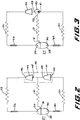
- Fig. 2 illustrates another refrigerant circuit, which is substantially similar to that illustrated in Fig. 1, except for the compression means, and like numerals are used to identify like components.
- the compression means 40 includes a first, low pressure compressor 41 having an inlet 42 and an outlet 43, and a second, high pressure compressor 44 having an inlet 45 and an outlet 46.
- the compressors 41 and 44 may be independent of each other with their own motors but they are controlled so that they operate simultaneously. Alternatively, they may be operated by a single motor as they operate at the same time.
- the refrigerant exiting freezer evaporator 20 is fed to the inlet 42 of low pressure compressor 41 which compresses that refrigerant to an intermediate pressure corresponding to the outlet pressure of the fresh food evaporator 21.
- Refrigerant from both the low pressure compressor 41 and the fresh food evaporator 21 is fed to the inlet of the high pressure compressor 44, which compresses the combined refrigerant to the high compressor outlet pressure.
- This high pressure refrigerant from exit 46 of the compressor 44 is fed to the condenser 22.
- Fig. 3 illustrates another refrigerant circuit which is substantially similar to that of Figs. 1 and 2, except that it uses a compression means including a valve and a single compressor, and the same numerals have been used identifying like components.
- a flow control or selection valve 50 having a pair of inlets 51 and 52 and an outlet 53, is connected between the outlets of the evaporators 20 and 21 and the inlet of a single stage compressor 54.
- the valve 50 functions to alternately connect each of evaporators 20 and 21 to the inlet of the compressor 54 so that, so long as the compressor 54 is operating, the valve 50 alternately conducts refrigerant from each of the evaporators 20 and 21 to compressor 54.
- compressor 54 When compressor 54 is connected to evaporator 20 it compresses refrigerant from the relatively low exit pressure of evaporator 20 to the high exit pressure of the compressor whereas, when compressor 54 is connected to evaporator 21 it compresses refrigerant from an intermediate pressure to the same compressor outlet pressure. Details of construction, operation and control of valves suitable for use in this circuit are shown and described in copending application EP-A-485146 incorporated herein by reference. It will be understood that a compression means in the form of a two stage compressor 23 as illustrated in Fig. 1, a compression means such as 40 including two separate compressors 41 and 44 as illustrated in Fig. 2; and a compression means including a valve 50 and compressor 54 arrangement, as shown in Fig. 3, may be utilized essentially interchangeably with various embodiments of the present invention.
Abstract
A household refrigerator (10) includes a freezer compartment (13) and a fresh food (14) compartment. The refrigerant system includes a compressor (23), a condenser (22), a first capillary tube (26) and a refrigerant phase separator (27) connected in series refrigerant flow relationship. A fresh food evaporator (21) to refrigerate the fresh food compartment (14) is connected to receive both vapor and liquid phase refrigerant from the phase separator (27) and to discharge refrigerant to the compressor (40). A freezer evaporator (20) to refrigerate the freezer compartment (13) is connected to receive liquid phase refrigerant from the phase separator (27) and to discharge refrigerant to the compressor (40).
Description
- The present invention relates generally to refrigeration systems and, for example household refrigerators.
- This application is related to U.S. Patent Nos. 4,910,972 and 4,918,942 issued to Heinz Jaster, EP-A-485146 (USSN 07/612,290) cofiled European Patent Application (USSN 787080) (9D -17760) for Lee J. Herbst et al.
- A typical present day household refrigerator includes a refrigeration system which circulates refrigerant continuously through a closed circuit including a compressor, a condenser, a capillary tube, and an evaporator back to the compressor. The refrigerant is a two-phase material having a liquid phase and a vapor phase. The refrigeration system operates to cause the refrigerant to repeatedly change from a liquid to a vapor and back to a liquid to transfer energy from inside the refrigerator by removing heat from the refrigerated compartments and expelling it to the atmosphere outside the refrigerator. In a typical refrigerator the evaporator is mounted in the freezer and a fan blows air across the evaporator with the air stream being split so that most of it circulates within the freezer while a portion of it is diverted to circulate through the fresh food compartment. In this way the freezer typically is maintained between about -10°F and +15°F while the fresh food compartment is maintained between about +33°F and +47°F. Such refrigerators do not operate at maximum possible efficiency as the refrigeration cycle produces all of its refrigeration effect at a temperature which is appropriate for the freezer, but is lower than is required to maintain the fresh food compartment at its appropriate temperature. The mechanical energy required to produce cooling at lower temperatures is greater than that required to produce cooling at higher temperatures and thus the typical simple vapor compression cycle uses more mechanical energy than one which produces cooling at the two temperature levels desired.
- U.S. Patents 4,910,972 and 4,918,942 disclose refrigeration systems in which a separate evaporator is used to provide the refrigeration for each of the freezer and fresh food compartments. The compression means in each of these patents takes the form of a two-stage compressor or dual compressors. Refrigerant from the freezer evaporator is fed to a low pressure stage, which elevates its pressure to an intermediate level. Vapor stage refrigerant from the fresh food compartment is combined with the refrigerant exiting the low pressure compression stage and this combined refrigerant is then fed to a high pressure compression stage, which raises the refrigerant pressure to the desired relatively high compressor outlet pressure.
- EP-A-0485146 discloses refrigeration circuits utilizing separate evaporators for the freezer compartment and the fresh food compartment. It discloses the use of a compression means combining a single stage compressor with a valve which selectively connects refrigerant from the outlet of the freezer evaporator and vapor stage refrigerant from the fresh food compartment alternately to the single compressor. Thus, when the valve feeds refrigerant from the freezer evaporator to the compressor, the compressor raises the refrigerant pressure all the way from the low pressure of the evaporator freezer to the desired high compressor outlet pressure. On the other hand, when the valve feeds vapor refrigerant from the fresh food evaporator to the compressor, the compressor only has to raise the pressure from an intermediate pressure level to the desired compressor outlet pressure.
- Each of the circuits in the above-described related patents and application connect the fresh food evaporator and the freezer evaporator in series relationship in the refrigerant flow circuit, with a phase separator connected between them. The phase separator functions to separate vapor phase refrigerant and liquid phase refrigerant with the liquid refrigerant being fed to the freezer evaporator and the vapor refrigerant being fed to the compressor means. In each of these refrigerant circuits, it is possible that, when the fresh food compartment needs substantial cooling, the fresh food evaporator will cause at least the vast majority of the refrigerant to vaporize. Thus, there may be insufficient liquid refrigerant in the phase separator to appropriately feed the freezer evaporator resulting in that evaporator being "starved" and the freezer receiving insufficient cooling.
- Embodiments of the present invention seek to provide: refrigerator including an improved refrigerant system;
a refrigerant system which minimizes the needed length of capillary tubing;
a household refrigerator with separate evaporators for the fresh food compartment and the freezer compartment in which the evaporators are connected in parallel refrigerant flow relationship between a refrigerant phase separator and the compressor means; and/or
a household refrigerator in which a plurality of evaporators are connected in parallel refrigerant flow relationship with each other in a unitary refrigerant circuit downstream of a refrigerant phase separator. - One embodiment of the present invention provides a household refrigerator has a fresh food evaporator to refrigerate a freezer compartment. The refrigeration system comprises compressor means, condenser means connected to receive refrigerant discharged from the compressor means, a refrigerant phase separator connected to receive refrigerant discharged from the condenser means. The fresh food and freezer evaporators are connected in parallel refrigerant flow relationship between the refrigerant phase separator and the compressor means so that liquid and vapor phase refrigerant flows from the phase separator for the fresh food evaporator and liquid phase refrigerant flows from the phase separator for the freezer evaporator. The invention, both as to organization and method of practice, may best be understood by reference to the following description taken in conjunction with accompanying drawings in which:
- FIG. 1 is a simplified schematic side elevational representation of a household refrigerator incorporating one form of the present invention;
- FIG. 2 is a schematic diagram of another refrigerant circuit incorporating the present invention and suitable for use in a household refrigerator; and
- FIG. 3 is a schematic diagram of another refrigerant circuit incorporating a form of the present invention and suitable for use in a household refrigerator.
- Referring now to Fig. 1, there is shown in simplified schematic form a
household refrigerator 10 including an insulatedouter wall 11 and an insulated dividingwall 12, separating the refrigerator into afreezer compartment 13 and a fresh food compartment 14.Doors - The refrigeration system for the
refrigerator 10 includes a first orfreezer evaporator 20, a second orfresh food evaporator 21, acondenser 22, and a compressor or compression means 23. These basic units are connected together by conduits in a fluid and vapor tight refrigerant circuit for circulation of two phase refrigerant. More specifically, thecompressor 23 is of the two stage type having a first or low pressure compression stage and an upper or high pressure compression stage. The high pressure refrigerant gas or vapor exits thecompressor 23 from anoutlet 24 and flows to thecondenser 22 where it is changed from a gas to a liquid. From thecondenser 22 the liquid refrigerant flows through a dryer 25 and a firstcapillary tube 26 to arefrigerant phase separator 27 positioned in fresh food compartment 14. -
Phase separator 27 includes ahousing 28 with aninlet 29 at its upper end to receive the refrigerant fromcapillary tube 26. Liquid phase refrigerant collects in lower portion ofhousing 28 while vapor phase refrigerant collects in the upper portion. Afirst outlet 30 connects with the lower portion ofhousing 28 which contains liquid phase refrigerant which flows throughoutlet 30 and a secondcapillary tube 34 to thefreezer evaporator 20. Fromevaporator 20, this refrigerant returns to alow pressure inlet 35 ofcompressor 23. Asecond outlet 31 connects with an intermediate point of thehousing 28. More specifically, the location and structure ofoutlet 31 is such that both liquid phase and vapor phase refrigerant flows throughoutlet 31 to thefresh food evaporator 21. Fromevaporator 21, this refrigerant returns to anintermediate pressure inlet 36 of compressor. - In this illustrative refrigerator with separate freezer and fresh food evaporators the
freezer evaporator 20 operates at a significantly lower temperature than thefresh food evaporator 21. Therefore, the vapor or gaseous refrigerant flowing from theevaporator 20 to thecompressor 23 is at a significantly lower pressure than the refrigerant flowing from theevaporator 21 to the compressor. The refrigerant from the freezer evaporator is fed to thelow pressure inlet 35 of twostage compressor 23 and is compressed by the first or low pressure stage to an intermediate pressure, generally corresponding to the exit pressure of thefresh food evaporator 21. The refrigerant exiting thefresh food evaporator 21 is fed to theintermediate pressure inlet 36 of thecompressor 23. The refrigerant from both the fresh food evaporator and the low pressure stage of the compressor then is compressed by the second stage to the relatively high exit pressure of the compressor. - A
thermostat 38 is mounted in the fresh food compartment and senses the ambient temperature within that compartment. When the thermostat senses a predetermined high temperature, normally in the vicinity of the upper temperature limit of that compartment, such as +47°F for example, it causes thecompressor 23 to be connected to a source of power such as the household electric system and the compressor then will continue to run until the thermostat senses a predetermined lower temperature, normally in the vicinity of the lower limit of the operating range of the fresh food compartment, such as +33°F for example. It will be understood that other, more involved control systems, may be used. For example, an additional thermostat that can be placed in the freezer compartment with the thermostats in the freezer and fresh food compartments cooperating to control the operation of the compressor, and thus the refrigeration system. It also will be understood that, for the sake of simplicity, various other components normally included in household refrigerators, such as for example lights and air circulating fans, have been omitted for the sake of simplicity. - With this arrangement refrigerant entering each of the
capillaries capillary tube 26 and the pressure drop in secondcapillary tube 34 is very low. All of these factors enhance the capability of using capillary tubes of commercially attractive size and length. For example, for an exemplary system, with a capacity of 800 BTH/hour and capillary tubing with an internal diameter of .031 inches, a total capillary tube length requirement of 70 inches was calculated. - It will be understood that the passage of the refrigerant conduits and wiring through the insulated
wall 11 is sealed to prevent air leakage. Thus, theopenings - Fig. 2, illustrates another refrigerant circuit, which is substantially similar to that illustrated in Fig. 1, except for the compression means, and like numerals are used to identify like components. The compression means 40 includes a first,
low pressure compressor 41 having aninlet 42 and anoutlet 43, and a second,high pressure compressor 44 having aninlet 45 and an outlet 46. Thecompressors freezer evaporator 20 is fed to theinlet 42 oflow pressure compressor 41 which compresses that refrigerant to an intermediate pressure corresponding to the outlet pressure of thefresh food evaporator 21. Refrigerant from both thelow pressure compressor 41 and thefresh food evaporator 21 is fed to the inlet of thehigh pressure compressor 44, which compresses the combined refrigerant to the high compressor outlet pressure. This high pressure refrigerant from exit 46 of thecompressor 44 is fed to thecondenser 22. - Fig. 3 illustrates another refrigerant circuit which is substantially similar to that of Figs. 1 and 2, except that it uses a compression means including a valve and a single compressor, and the same numerals have been used identifying like components. A flow control or
selection valve 50, having a pair ofinlets evaporators single stage compressor 54. Thevalve 50 functions to alternately connect each ofevaporators compressor 54 so that, so long as thecompressor 54 is operating, thevalve 50 alternately conducts refrigerant from each of theevaporators compressor 54. Whencompressor 54 is connected to evaporator 20 it compresses refrigerant from the relatively low exit pressure ofevaporator 20 to the high exit pressure of the compressor whereas, whencompressor 54 is connected to evaporator 21 it compresses refrigerant from an intermediate pressure to the same compressor outlet pressure. Details of construction, operation and control of valves suitable for use in this circuit are shown and described in copending application EP-A-485146 incorporated herein by reference. It will be understood that a compression means in the form of a twostage compressor 23 as illustrated in Fig. 1, a compression means such as 40 including twoseparate compressors valve 50 andcompressor 54 arrangement, as shown in Fig. 3, may be utilized essentially interchangeably with various embodiments of the present invention.
Claims (4)
- A refrigerator comprising:
compressor means;
condenser means connected to receive refrigerant discharged from said compressor means;
first capillary tube means connected to receive refrigerant discharged from said condenser means;
a refrigerant phase separator connected to receive refrigerant discharged from said first refrigerant expansion means and effective to separate the refrigerant into vapor phase and liquid phase refrigerant;
a fresh food compartment, a fresh food evaporator for refrigerating said fresh food compartment and connected to receive vapor and liquid phase refrigerant discharged from said phase separator; and
a freezer compartment and a freezer evaporator for refrigerating said freezer compartment and connected to receive liquid phase refrigerant discharged from said phase separator;
said fresh food and said freezer evaporators being connected to discharge refrigerant to said compressor means. - A refrigerator as set forth in Claim 1, further including: second capillary tube means connected in refrigerant flow relationship between said phase separator and said freezer evaporator.
- A refrigerator as set forth in Claim 1, wherein said phase separator includes an outlet constructed and positioned in said phase separator and connected in refrigerant flow relationship with said fresh food evaporator for supply of vapor and liquid phase refrigerant to said fresh food evaporator.
- A refrigerator as set forth in Claim 1, wherein said phase separator includes a liquid phase exit positioned below the minimum operating level of liquid refrigerant in said phase separator and connected in refrigerant flow relationship with said freezer evaporator for supply of liquid phase refrigerant to said freezer evaporator.
Applications Claiming Priority (2)
| Application Number | Priority Date | Filing Date | Title |
|---|---|---|---|
| US78708191A | 1991-11-04 | 1991-11-04 | |
| US787081 | 1991-11-04 |
Publications (1)
| Publication Number | Publication Date |
|---|---|
| EP0541328A1 true EP0541328A1 (en) | 1993-05-12 |
Family
ID=25140366
Family Applications (1)
| Application Number | Title | Priority Date | Filing Date |
|---|---|---|---|
| EP92310048A Withdrawn EP0541328A1 (en) | 1991-11-04 | 1992-11-03 | Refrigeration systems |
Country Status (3)
| Country | Link |
|---|---|
| EP (1) | EP0541328A1 (en) |
| JP (1) | JPH05223369A (en) |
| CA (1) | CA2080197A1 (en) |
Cited By (6)
| Publication number | Priority date | Publication date | Assignee | Title |
|---|---|---|---|---|
| EP0935106A3 (en) * | 1998-02-06 | 2000-05-24 | SANYO ELECTRIC Co., Ltd. | Multi-stage compressing refrigeration device and refrigerator using the device |
| US20120137724A1 (en) * | 2010-12-07 | 2012-06-07 | Brent Alden Junge | Dual evaporator refrigeration system |
| EP2933584A1 (en) * | 2014-04-16 | 2015-10-21 | Valeo Systemes Thermiques | Coolant circuit |
| EP2198211A4 (en) * | 2007-10-17 | 2016-01-13 | Carrier Corp | A medium- and low-temperature integrated refrigerating/freezing system |
| US10151522B2 (en) | 2016-01-27 | 2018-12-11 | Haier Us Appliance Solutions, Inc. | Microchannel condenser and dual evaporator refrigeration system |
| CN115289752A (en) * | 2022-08-31 | 2022-11-04 | 佛山市冰元制冷设备有限公司 | Refrigerating system unit for food quick-freezing refrigerator |
Families Citing this family (1)
| Publication number | Priority date | Publication date | Assignee | Title |
|---|---|---|---|---|
| JP5402164B2 (en) * | 2009-03-31 | 2014-01-29 | 株式会社富士通ゼネラル | Refrigeration cycle equipment |
Citations (2)
| Publication number | Priority date | Publication date | Assignee | Title |
|---|---|---|---|---|
| DE1022611B (en) * | 1954-10-11 | 1958-01-16 | Licentia Gmbh | Arrangement for refrigerators with a specially cooled freezer compartment |
| US5036680A (en) * | 1989-06-14 | 1991-08-06 | Nippondenso Co., Ltd. | Refrigeration separator with means to meter quality of refrigerant to the evaporator |
-
1992
- 1992-10-08 CA CA 2080197 patent/CA2080197A1/en not_active Abandoned
- 1992-10-30 JP JP29250692A patent/JPH05223369A/en not_active Withdrawn
- 1992-11-03 EP EP92310048A patent/EP0541328A1/en not_active Withdrawn
Patent Citations (2)
| Publication number | Priority date | Publication date | Assignee | Title |
|---|---|---|---|---|
| DE1022611B (en) * | 1954-10-11 | 1958-01-16 | Licentia Gmbh | Arrangement for refrigerators with a specially cooled freezer compartment |
| US5036680A (en) * | 1989-06-14 | 1991-08-06 | Nippondenso Co., Ltd. | Refrigeration separator with means to meter quality of refrigerant to the evaporator |
Cited By (8)
| Publication number | Priority date | Publication date | Assignee | Title |
|---|---|---|---|---|
| EP0935106A3 (en) * | 1998-02-06 | 2000-05-24 | SANYO ELECTRIC Co., Ltd. | Multi-stage compressing refrigeration device and refrigerator using the device |
| EP2198211A4 (en) * | 2007-10-17 | 2016-01-13 | Carrier Corp | A medium- and low-temperature integrated refrigerating/freezing system |
| US20120137724A1 (en) * | 2010-12-07 | 2012-06-07 | Brent Alden Junge | Dual evaporator refrigeration system |
| EP2933584A1 (en) * | 2014-04-16 | 2015-10-21 | Valeo Systemes Thermiques | Coolant circuit |
| FR3020130A1 (en) * | 2014-04-16 | 2015-10-23 | Valeo Systemes Thermiques | FRIGORIGENE FLUID CIRCUIT |
| CN105004087A (en) * | 2014-04-16 | 2015-10-28 | 法雷奥热系统公司 | Coolant circuit |
| US10151522B2 (en) | 2016-01-27 | 2018-12-11 | Haier Us Appliance Solutions, Inc. | Microchannel condenser and dual evaporator refrigeration system |
| CN115289752A (en) * | 2022-08-31 | 2022-11-04 | 佛山市冰元制冷设备有限公司 | Refrigerating system unit for food quick-freezing refrigerator |
Also Published As
| Publication number | Publication date |
|---|---|
| CA2080197A1 (en) | 1993-05-05 |
| JPH05223369A (en) | 1993-08-31 |
Similar Documents
| Publication | Publication Date | Title |
|---|---|---|
| EP0541343B1 (en) | Refrigeration systems | |
| US4910972A (en) | Refrigerator system with dual evaporators for household refrigerators | |
| EP0541324A1 (en) | Refrigeration systems | |
| US5134859A (en) | Excess refrigerant accumulator for multievaporator vapor compression refrigeration cycles | |
| US7216494B2 (en) | Supermarket refrigeration system and associated methods | |
| CA2190018A1 (en) | Refrigerator having high efficiency multi-evaporator cycle (h.m. cycle) and control method thereof | |
| US7721559B2 (en) | Multi-type air conditioner and method for controlling the same | |
| US10041716B2 (en) | Refrigerator | |
| US5157943A (en) | Refrigeration system including capillary tube/suction line heat transfer | |
| US10197324B2 (en) | Refrigerator and method for controlling the same | |
| US5722248A (en) | Operating control circuit for a refrigerator having high efficiency multi-evaporator cycle (h.m. cycle) | |
| US4022032A (en) | Refrigeration system | |
| EP0541328A1 (en) | Refrigeration systems | |
| EP0624763A1 (en) | Free-draining evaporator for refrigeration system | |
| EP0485147B1 (en) | Refrigeration system | |
| EP0374688A2 (en) | Refrigerator system with dual evaporators for household refrigerators | |
| KR101000053B1 (en) | An apparatus of a vapor and oil division for different capacity compressor in an air conditioner | |
| KR102150058B1 (en) | A refrigerator and a control method the same | |
| EP3078925A1 (en) | Variable capacity condensing unit | |
| MX9605554A (en) | Refrigerator and control method therefor. | |
| MY115998A (en) | Refrigerator having high efficiency multi-evaporator cycle (h.m. cycle) and control method thereof | |
| KR970016466A (en) | Refrigerator chiller |
Legal Events
| Date | Code | Title | Description |
|---|---|---|---|
| PUAI | Public reference made under article 153(3) epc to a published international application that has entered the european phase |
Free format text: ORIGINAL CODE: 0009012 |
|
| AK | Designated contracting states |
Kind code of ref document: A1 Designated state(s): DE ES FR GB IT SE |
|
| 17P | Request for examination filed |
Effective date: 19931102 |
|
| 17Q | First examination report despatched |
Effective date: 19940509 |
|
| STAA | Information on the status of an ep patent application or granted ep patent |
Free format text: STATUS: THE APPLICATION IS DEEMED TO BE WITHDRAWN |
|
| 18D | Application deemed to be withdrawn |
Effective date: 19940920 |