EP0540342B1 - Removal of organics and volatile metals from soils using thermal desorption - Google Patents
Removal of organics and volatile metals from soils using thermal desorption Download PDFInfo
- Publication number
- EP0540342B1 EP0540342B1 EP92309941A EP92309941A EP0540342B1 EP 0540342 B1 EP0540342 B1 EP 0540342B1 EP 92309941 A EP92309941 A EP 92309941A EP 92309941 A EP92309941 A EP 92309941A EP 0540342 B1 EP0540342 B1 EP 0540342B1
- Authority
- EP
- European Patent Office
- Prior art keywords
- chamber
- contaminants
- contaminated
- water
- gas
- Prior art date
- Legal status (The legal status is an assumption and is not a legal conclusion. Google has not performed a legal analysis and makes no representation as to the accuracy of the status listed.)
- Expired - Lifetime
Links
Images

Classifications
-
- F—MECHANICAL ENGINEERING; LIGHTING; HEATING; WEAPONS; BLASTING
- F26—DRYING
- F26B—DRYING SOLID MATERIALS OR OBJECTS BY REMOVING LIQUID THEREFROM
- F26B25/00—Details of general application not covered by group F26B21/00 or F26B23/00
- F26B25/005—Treatment of dryer exhaust gases
- F26B25/006—Separating volatiles, e.g. recovering solvents from dryer exhaust gases
-
- B—PERFORMING OPERATIONS; TRANSPORTING
- B09—DISPOSAL OF SOLID WASTE; RECLAMATION OF CONTAMINATED SOIL
- B09B—DISPOSAL OF SOLID WASTE
- B09B3/00—Destroying solid waste or transforming solid waste into something useful or harmless
- B09B3/40—Destroying solid waste or transforming solid waste into something useful or harmless involving thermal treatment, e.g. evaporation
- B09B3/45—Steam treatment, e.g. supercritical water gasification or oxidation
-
- B—PERFORMING OPERATIONS; TRANSPORTING
- B09—DISPOSAL OF SOLID WASTE; RECLAMATION OF CONTAMINATED SOIL
- B09C—RECLAMATION OF CONTAMINATED SOIL
- B09C1/00—Reclamation of contaminated soil
- B09C1/06—Reclamation of contaminated soil thermally
Definitions
- This invention relates to an apparatus and method for removing volatile and semi-volatile contaminants from solid materials and, more particularly, to an apparatus and method for thermal desorption of organics and volatile metals from soils to separate the contaminants from the soil.
- the contaminated soil may be treated by destruction of the contaminants, such as by incineration or by pyrolysis, or by separation of the contaminants from the soil, such as by thermal desorption.
- the contaminants are heated under oxygen concentrations and residence time to a temperature effective to decompose the contaminants.
- pyrolysis the contaminants are heated in the absence of oxygen for a predetermined residence time to a temperature effective to decompose the contaminants.
- thermal desorption the contaminants are heated under oxygen concentrations and residence time to a temperature effective to avoid decomposition of the contaminants, thereby enabling the separation of the volatilized contaminants from the soil.
- an incinerator is the apparatus disclosed in U.S. Patent 4,050,900 (Hobbs et al.), which is herein incorporated by reference for its description of an incineration system utilizing a conveyor belt.
- Materials are moved through a combustion chamber on a conveyor belt.
- the materials are incinerated, due to a combination of infrared heating means and combustion of the devolatilized organics, which releases combustion gases.
- incineration reduces the volume of waste requiring disposal, highly toxic combustion products are produced, such as dioxin, which must be effectively treated in the afterburner and scrubbing section. If fixed based incineration facilities are used, large volumes of contaminated materials must be packaged and transported to licensed incineration facilities, which have limited capacity.
- U.S. Patent 4,782,625 discloses volatilizing organic compounds in a rotating cylinder having plural flights for moving soil through the cylinder.
- the material drying means, filtering means, scrubbing means, and bed of activated carbon are individually mounted on the bed of trailers to facilitate transportation of the equipment.
- Prior Art Document WO-A-91/15248 discloses a method for removing contaminants from contaminated material, comprising the steps of: moving the contaminated material positioned on a belt conveyor through a chamber from an inlet end of the chamber to a discharge end of the chamber; heating the contaminated material positioned on the belt conveyor in the chamber as the contaminated material moves through the chamber to a temperature effective for volatilizing the contaminants and for producing a processed material that is substantially decontaminated; maintaining the temperature effective to substantially avoid incineration of the contaminants; discharging the volatilized contaminants from the chamber; condensing at least a portion of the volatilized contaminants discharged from the chamber for producing a condensate; and discharging the processed material from the chamber through the discharge end of the chamber.
- the present invention resides in a method for removing contaminants from contaminated material, comprising the steps of:
- the invention also consists in an apparatus for removing volatile and semi volatile contaminants from contaminated materials, comprising:
- the thermal desorption unit further comprises means for passing a gas above the contaminated material positioned on the belt conveyor and countercurrent to the movement of the contaminated material through the chamber for carrying the volatilized contaminants from the chamber and a quencher positioned at one end of the chamber for condensing at least a portion of the volatilized contaminants discharged from the chamber.
- the thermal desorption unit and process utilizing a belt conveyor with indirect heating within the chamber enables a larger quantity of the contaminated material to be decontaminated in a smaller chamber with a shorter residence time than is required for volatilization of the contaminants utilizing other means, such as a rotary kiln.
- dust carry over is minimized, the residence time is controlled, and higher matrix temperatures are achievable.
- the invention described herein provides an apparatus and method for thermally desorbing contaminants from contaminated solid materials, thereby separating the volatile contaminants from the solid materials.
- a thermal desorption unit referred to generally as 10, is capable of evaporating water, volatile contaminants, such as PCB's (polychlorinated biphenyls), PHC's (petroleum hydrocarbons), and PCP's (pentachlorophenols), and semi-volatile metals or metallic compounds, such as antimony, lead, cadmium, zinc, or mercury.
- volatile contaminants such as PCB's (polychlorinated biphenyls), PHC's (petroleum hydrocarbons), and PCP's (pentachlorophenols)
- semi-volatile metals or metallic compounds such as antimony, lead, cadmium, zinc, or mercury.
- the thermal desorption unit 10 includes a chamber 20.
- the chamber 20 is a housing, having a plurality of walls, which is substantially airtight.
- the chamber 20 has an inlet end 30 for receiving material into the chamber 20 and a discharge end 32 for discharging material from the chamber 20.
- the chamber 20 is constructed of mild carbon steel and is insulated with ceramic fiber. To protect the shell from corrosive volatiles, the interior steel surfaces are sprayed with a corrosion resistant material before installing the insulation, and a stainless steel vapor barrier, which may include an additional layer of fiber insulation, is positioned adjacent to the ceramic fiber.
- the chamber 20 houses a belt conveyor 36, which may be constructed from a metal alloy or ceramic cloth, for transporting the contaminated material through the chamber 20.
- the belt conveyor 36 which is supported on rollers 38, has an upper belt portion 40 for moving the material from the inlet end 30 to the discharge end 32 of the chamber 20 and a lower belt portion 42 positioned below the upper belt portion 38.
- a rotary drier such as a rotary kiln or rotating drum, cannot be substituted for the belt conveyor 36 due to the variable residence time of the material within the rotary drier, the limited heat transfer rates, the limited range of temperatures of the material, and the aeration of particulates within the volatilized contaminants.
- turning bars Positioned within the chamber 20 are turning bars (not shown) with an array of attached teeth which slowly rake through the material layer positioned on the belt conveyor 36 as the material moves through the chamber 20, for increasing contaminant removal.
- the plurality of turning bars are positioned along the length of the belt conveyor 36 with the teeth positioned so that all of the material is turned as it moves along the length of the belt conveyor 36.
- the turning bars turn the material to ensure that all of the contaminants are exposed to the heat, but do not create particulates floating in the space above the belt conveyor 36.
- the turning bars do not disturb the rate of movement of the material on the conveyor belt 36 as compared to a rotary kiln.
- a rotary kiln overturns the material creating the possibility of a portion of the material progressing through the chamber at a different rate than the rate of progress of another portion of the material progressing through the chamber.
- a consistent rate of movement of the contaminated material through the chamber 20 on the belt conveyor 36 enables a known residence time to be determined, as compared to the variable amount of time that a particular portion of material remains within a rotary kiln.
- a plurality of heaters 50 are positioned above the belt conveyor 36 for heating the material as the material moves through the chamber 20 on the belt conveyor 36.
- the heaters 50 may be infrared heaters, radio frequency heaters, or microwave heaters. The utilization of these heaters allows very high temperatures to be obtained in the contaminated material because heat transfer surfaces and their materials of construction are not a consideration.
- infrared heaters are utilized, thereby enabling the material to be directly heated by convection and conduction and indirectly heated by radiation. Because the material moves through the chamber 20 at a constant rate and because the requisite temperatures can be obtained by utilization of the belt conveyor 36, the residence time of the contaminated material in the chamber 20 can be precisely controlled.
- the heaters 50 are capable of heating the contaminated material to a temperature effective to volatilize the contaminants, without incinerating or pyrolyzing the contaminants.
- the heaters 50 heat the material to a temperature between the range of approximately 212°F (100°C) to 1250°F (680°C) for volatilizing the contaminants from the solid material.
- the material is heated to at least about 850°F (450°C) for a PCB contaminated material.
- the heaters 50 are connected to a control panel (not shown) for supplying and controlling electric power to the heaters 50.
- the chamber 20 is substantially airtight for preventing air from entering the chamber 20. Reducing the quantity of air within the chamber 20 reduces the possibility of volatilized contaminants leaking from the chamber 20 into the atmosphere. By preventing air from entering the chamber 20, there is a smaller volume of gas circulation within the chamber 20, which minimizes dust and particulate materials flowing above the belt conveyor 36, thereby increasing the efficiency of removal of the volatilized contaminants. Also, because the conditions necessary for incineration are a combination of the quantity of air, the temperature, and the residence time within the chamber 20, the prevention of air from the chamber 20 reduces the possibility of incineration of the contaminants, thereby minimizing the formation of highly toxic combustion products, such as dioxins and dibenzofurans.
- a feed conveyor 52 moves the contaminated material from a supply source, such as dryer 54, to a feed hopper 56, which is positioned adjacent to the inlet end 30 of the chamber 20.
- the feed hopper 56 may have a plurality of screw conveyors (not shown) rotatably mounted within an elongated housing, for moving the contaminated material into the chamber 20.
- the screw conveyors filled with the contaminated material act as a seal and prevent air from entering the chamber 20.
- a conveyor 58 positioned adjacent to the discharge end 32 of the chamber 20 removes the substantially decontaminated processed material from the chamber 20.
- the chamber 20 has a gas inlet duct 62 for passing a flow a gas into the chamber 20 countercurrent to the movement of the contaminated material through the chamber 20.
- the transport gas will carry the volatilized contaminants from the discharge end 32 of the chamber 20 towards the inlet end 30 of the chamber 20.
- the gas will flow above the contaminated material positioned on the belt conveyor 36.
- the countercurrent flow of the transport gas has a velocity sufficient to sweep the contaminants from the chamber 20, such as a velocity of approximately 0.2 ft/sec (0.06 m/sec) to 2.5 ft/sec (0.75 m/sec).
- the gas carrying the contaminants is discharged from the chamber 20 through a gas outlet duct 64 positioned near the inlet end 30 of the chamber 20.
- the dryer 54 which is optional, is used to evaporate water from the contaminated material prior to the contaminated material entering the chamber 20. By removing the water prior to thermal desorption, the quantity of heat and residence time required within the chamber 20 to desorb the contaminants is less than that required to desorb the contaminants and the water within the chamber 20.
- the processed material discharged from the chamber 20 is quenched with water for cooling the material.
- the steam produced by the quenching may be recirculated through the system by passing the steam into the chamber 20 as the transport gas for carrying the volatilized contaminants from the chamber 20.
- the steam is not admitted into the chamber 20 until the temperature of the outlet soil from the chamber 20 is greater than 212°F (100°C) for preventing the steam from condensing on the soil surface.
- nitrogen or carbon dioxide may be used as the gas for carrying the volatilized contaminants from the chamber 20.
- a qencher 70 is positioned adjacent to the chamber 20 for condensing the gas exiting from the gas outlet duct 64 of the chamber 20.
- a direct, water spray contact condenser is utilized. Water is sprayed into the gas mixture in the qencher 70 to produce a water saturated gas.
- the gas may be quenched to a temperature of approximately 212°F (100°C) or lower.
- the liquid condensate may be easily transported to another site for further processing.
- the use of a quencher to process the volatilized contaminants does not produce toxic by-products, as is produces by incineration of the volatilized contaminants.
- a scrubber 80 is positioned adjacent to the quencher 70 for removing particulates from the water saturated gas.
- a high pressure spray impacts the gas within the scrubber 80, the particulates attach to droplets of water.
- the particulates, including the contaminants, are removed from the scrubber 80 separately from the removal of gas from the scrubber 80.
- a Calvert Collision Scrubber from Calvert Inc. may be utilized as the scrubber 80.
- Gas entering the Calvert Collision Scrubber is split into two gas streams prior to entering the primary atomization zones, similar to venture scrubber throats.
- the drops of water collect particles as the drops of water are accelerated toward the collision zone in the center of the throat.
- the drops of water because of their inertia, travel into the opposing gas stream, where the drops attain in a relative velocity twice that in the primary atomization zone.
- This collision process shreds the water drops into fine drops, which more effectively collect submicron particles and produce a large mass transfer area for gas absorption.
- the substantially particulate-free gas stream flows to a de-entrainment section, where liquid droplets are removed, for separating the liquid from the gas.
- the scrubbed gas is drawn from the scrubber 80 by an induced draft blower 84.
- a portion of the gas is passed through a gas cleaning system 86, such as a stack with activated carbon, which provides an additional organic contaminant removal step.
- a portion of the gas may be recycled by passing the gas into the chamber 20 as the transport gas.
- the water removed from the scrubber 80 is passed to a water treatment system 90, such as an oil/water separator.
- the water treatment system 90 removes contaminants, such as PCB and PHC, and soil fines.
- the contaminants discharged from the water treatment system 90 may be sent to an incineration facility for further processing.
- a portion of the treated water is passed through an air cooler 92 and returned to the quencher 70, for cooling the gas outlet stream from chamber 20.
- the air cooler 92 may comprise an indirect, water cooled spray tower or dry cooling system.
- a portion of the treated water is passed through a residual treatment system 94, which may include activated carbon, ion exchange, precipitation and flocculation, for providing an additional treatment process for the water.
- the water passed through the residual treatment system 94 is recycled by using the water to quench the processed soil exiting the chamber 20.
- a control system houses the controls required to operate the subsystems of the thermal desorption process.
- a control cabinet houses the system alarms, annunciators, recorder, process controllers, and process indicators.
- the hourly throughput for the thermal desorption process is at least about 1 ton (900 kg) per hour of soil.
- the throughput is at least about 10 tons (9,000 kg) per hour.
- the thermal desorption unit 10 permits at least approximately 15 tons (13,600 kg) per hour throughput of soil.
- the residence time of the soil in the chamber 20 of the thermal desorption unit 10 is within the range of approximately five minutes to 60 minutes.
- the estimated final PCB levels achievable utilizing the thermal desorption unit and process are approximately 1 ppm or less.
- the contaminated material is heated to above approximately 850°F (450°C) with a residence time of approximately two to 20 minutes at approximately 850°F (450°C).
- approximately 20,700 lb/hr (9,400 kg/hr) of soil contaminated with PCB's can be processed in the chamber 20 at a temperature of approximately 950°F (510°C) and a residence time of approximately 6 minutes.
- PCB's are used for illustration only. Organics, volatile metals, and their salts can also be removed.
- the capacity of the thermal desorption system is dependent upon the characteristics of the feed material.
- the feed capacity is primarily determined by the contaminant desorption rates, the thermal conductivity, and the percent moisture of the feed. Other important variables are heat capacity of the bed of contaminated material, thermal conductivity of the bed, density of the soil, and absorptivity of the soil.
- Contaminated material may be transported from a contamination site to a permanent facility housing the thermal desorption unit 10.
- the thermal desorption unit 10 may be transported to the contamination site for on site processing of the contaminated material.
- the chamber 20 of the thermal desorption unit 10, the feed hopper 56, the belt conveyor 36, and the heaters 50 are housed on a first trailer 100.
- a second trailer 102 houses a plurality of the water treatment systems 90 and a plurality of the carbon absorption columns 94.
- a third trailer 104 houses the quencher 70, the scrubber 80, the induced draft blower 84, and the gas cleaning system 86.
- a fourth trailer 106 houses the air cooler 92.
- Various other pieces of equipment, such as transformers, pumps, and the control system, may be housed on additional trailers (not shown).
- Preparation equipment processes the contaminated material to produce a feed stream with individual pieces smaller than 1 inch.
- the contaminated material is placed through stream 110 into a weigh hopper 111, which maintains a constant feed rate of contaminated material to chamber 20.
- dryer 54 is optional. If the contaminated material is conveyed from the weigh hopper 111 into the chamber 20, the heaters 50 within the chamber 20 will evaporate the water from the contaminated material prior to thermally desorbing the contaminants. If the contaminated material is conveyed from the weigh hopper 111 to the dryer 54 through stream 112, then the contaminated material is heated within the dryer 54, which evaporates the water from the contaminated material. By removing the water prior to entry of the contaminated material into the chamber 20, less energy is needed to thermally desorb the contaminants from the material and the residence time of the contaminated material within the chamber 20 is reduced.
- the contaminated material may be a wet sludge, which may clog the screw conveyors of the feed hopper 56, by drying the contaminated material in the dryer 54 prior to entry of the material into the chamber 20, the wet sludge is converted to separate fragments of material, which do not clog the feed hopper 56. Also, the dried material is more readily handleable, than the wet sludge.
- the contaminated material is conveyed to the feed hopper 56 on the feed conveyor 52, which is substantially enclosed.
- the contaminated material falls through the opening in the top of the chamber 20 and forms a one to two inch (2.5 to 5 cm) layer across the width of the belt conveyor 36.
- the chamber 20 of the infrared thermal desorption unit 10 operates at a slight vacuum, such as about 0.1 inch (0.2 cm) of water, for reducing the leakage of volatilized contaminants from the chamber 20 into the atmosphere.
- the contaminated material is heated by the heaters 50 as the material moves through the chamber 20 positioned on the belt conveyor 36.
- the material will be heated to a temperature effective to volatilize the contaminants from the soil, such as within the range of 212°F (100°C) to 1250°F (680°C).
- a flow of gas through stream 113 enters the chamber 20 through the gas inlet duct 62 and transports the volatilized contaminants countercurrent to the flow of the contaminated material on the belt conveyor 36 above the belt conveyor 36.
- the gas and the volatilized contaminants exit the chamber 20 through the gas outlet duct 64.
- the vapor product off-gas including the gas and the volatilized contaminants passes through stream 114 to the quencher 70, which provides a cold water shower for lowering the temperature of the gas to below its saturation point to condense the vapor product off-gas.
- the gas stream passes through stream 116 to the scrubber 80, which uses water droplet contact for removing solids and contaminants from the gas stream. A gas stream and a contaminated liquid condensate will exit from the scrubber 80.
- the cleaned gas stream is drawn through stream 118 by the induced draft blower 84 from the scrubber 80.
- a portion of the cleaned gas stream may pass through stream 120 for entry into the chamber 20 through the gas inlet duct 62 for recycling the gas.
- the remainder of the cleaned gas stream passes through stream 122 into the gas cleaning system 86 for an additional cleaning step prior to discharge into the atmosphere.
- the contaminated liquid condensate passes through stream 124 into the water treatment system 90 for removal of an oil contaminant sludge phase using gravitational settlement.
- the cleaned water may also be additionally treated by flocculation, gravity settling, or carbon absorption to remove the remainder of the contaminants.
- the oil sludge and absorbed contaminants are passed through stream 126 and are removed from the site for further processing.
- the decontaminated water passes through stream 128 and a portion of the decontaminated water is passed through stream 130 into the air cooler 92 and then through stream 132 into the quencher 70 for recycling the water. A portion of the decontaminated water is passed through stream 134 into the residual treatment system 94 for removing residual organics and metals and then passed through steam 136 for quenching the clean soil exiting the chamber 20 for recycling the water.
- Clean soil drops off the end of the belt conveyor 36 and onto the conveyor 58, exiting the thermal desorption unit 10 through the discharge end 32 of the chamber 20. After the quenching of the clean soil discharged from the chamber 20 to lower the temperature of the soil, the soil is returned to the environment. At least a portion of the steam produced by quenching the clean soil is recycled by passing the steam into the chamber 20 as the transport gas.
- the invention provides an apparatus and method for removing volatile contaminants from contaminated soil by heating the contaminated material under oxygen concentrations, temperature conditions, and residence time effective to thermally desorb the contaminants from the material without incinerating the contaminants.
- FIGURE THERMAL DESORPTION UNIT 10 1 DRYER (OPTIONAL) 54 1 QUENCHER 70 1 QUENCHER 70 4 SCRUBBER 80 1 SCRUBBER 80 4 INDUCED DRAFT BLOWER 84 4 GAS CLEANING SYSTEM 86 4 WATER TREATMENT SYSTEM 90 1 WATER TREATMENT SYSTEM 90 3 AIR COOLER 92 1 AIR COOLER 92 5 CARBON ABSORPTION COLUMN 94 1 WEIGH HOPPER 111 1
Description
- This invention relates to an apparatus and method for removing volatile and semi-volatile contaminants from solid materials and, more particularly, to an apparatus and method for thermal desorption of organics and volatile metals from soils to separate the contaminants from the soil.
- The contamination of soils, sludges, ashes, and other solids by organics and heavy metals is a significant environmental problem. Due to the large volumes involved and expensive disposal costs for these solids, there is a need to reduce the volume of waste requiring disposal.
- The contaminated soil may be treated by destruction of the contaminants, such as by incineration or by pyrolysis, or by separation of the contaminants from the soil, such as by thermal desorption. During incineration, the contaminants are heated under oxygen concentrations and residence time to a temperature effective to decompose the contaminants. During pyrolysis, the contaminants are heated in the absence of oxygen for a predetermined residence time to a temperature effective to decompose the contaminants. During thermal desorption, the contaminants are heated under oxygen concentrations and residence time to a temperature effective to avoid decomposition of the contaminants, thereby enabling the separation of the volatilized contaminants from the soil.
- An example of an incinerator is the apparatus disclosed in U.S. Patent 4,050,900 (Hobbs et al.), which is herein incorporated by reference for its description of an incineration system utilizing a conveyor belt. Materials are moved through a combustion chamber on a conveyor belt. As the materials advance through the chamber, the materials are incinerated, due to a combination of infrared heating means and combustion of the devolatilized organics, which releases combustion gases. Although incineration reduces the volume of waste requiring disposal, highly toxic combustion products are produced, such as dioxin, which must be effectively treated in the afterburner and scrubbing section. If fixed based incineration facilities are used, large volumes of contaminated materials must be packaged and transported to licensed incineration facilities, which have limited capacity.
- The EPA Applications Analysis Report, Shirco Infrared Incineration System, June 1989, pages 39-42, discloses utilizing infrared heating elements to heat material positioned on a conveyor belt, which results in desorption of the contaminants from the material within a primary chamber, followed by incineration of the desorbed contaminants in the primary chamber. If combustion of the desorbed contaminants is not complete within the primary chamber, then the desorbed contaminants are incinerated in a secondary chamber, which produces toxic combustion products.
- In another incineration process, U.S. Patent 3,954,069 (Loken), sludge is indirectly heated to produce an exhaust gas of air, malodorous gases, and water, which is passed to a condenser. In the condenser, only water is condensed and removed so that the "contaminant" malodorous gas passes to an incinerator.
- A process similar to incineration is disclosed in Process Technology and Flowsheets, McGraw-Hill, 1979, pages 225-226, in which waste is pyrolyzed at 900°F to provide oil vapor, gas vapor and water vapor. The vapors are quenched to form pyrolytic fuel oil and off-gas. However, during pyrolysis, the contaminants are decomposed, which may result in residual compounds, such as materials which are hazardous, toxic, or require regulation by the Environmental Protection Agency, remaining in the material.
- An example of thermal treatment of soil is disclosed in U.S. Patent 4,738,206 (Noland). Contaminated soil is conveyed through a chamber by a screw conveyor with internally heated flights and vapor stripped at a temperature below the boiling temperatures of the contaminants. This approach, however, will result in the production of very large volumes of gas, which then must be treated for contaminant removal.
- Another example of thermal desorption of soil is disclosed in U.S. Patents 4,977,839 (Fochtman et al.) and 4,864,942 (Fochtman et al.). Contaminated materials, which are placed in a rotary kiln, are subjected to a temperature effective to volatilize the contaminants, but below the incineration temperature, for a period of time sufficient to effect the desired degree of separation of contaminants. However, incineration is due to a combination of the presence of an oxidizing substance and the residence time of the material at a particular time, and is not due to the temperature at which the process occurs.
- U.S. Patent 4,782,625 (Gerken et al.) discloses volatilizing organic compounds in a rotating cylinder having plural flights for moving soil through the cylinder. The material drying means, filtering means, scrubbing means, and bed of activated carbon are individually mounted on the bed of trailers to facilitate transportation of the equipment.
- Another description of processes to treat contaminated soil using a rotary kiln can be found in Contaminated Land Reclamation and Treatment, Michael A. Smith ed., Plenum Press, pages 37-90, "On-Site Processing of Contaminated Soil" by W.H. Rulkens, 1985. Incineration, treatment with catalysts, and low temperature vaporization of contaminants are disclosed. In low temperature treatment of off-gas, Rulkens discloses the use of steam as a carrier gas, cyclone filtering, condensing, gas scrubbing, separation of gas from the resulting contaminated liquid, and filtering the gas through activated carbon before discharging the gas.
- However, utilization of the rotary kiln, the rotating cylinder, or the screw conveyor has several disadvantages. Due to the tumbling of the material within the drum, which may cause portions of the material to progress through the drum at different rates, the residence time of the material within the rotating drum to effect the desired degree of separation is variable.
- Another disadvantage to the utilization of the rotary kiln and the screw conveyor is the limited heat transfer rates through the shell of the kiln or through the flights of the screw, which limits the throughput of these processes. Also, the soil or debris final temperature is limited by the materials of construction of the kiln and screw conveyor because the flame temperature required to obtain the desired heat transfer through the material to volatilize the contaminants may cause damage to the kiln and screw conveyor, such as material fatigue and melting of the rotary kiln and screw conveyor. Utilization of a lower temperature to volatilize the contaminants requires a longer residence time of the material within the thermal desorption unit.
- Another disadvantage to the utilization of a rotating drum is the production of dust within the drum due to the tumbling of the material, which makes it difficult to treat the off-gas, produces a large amount of contaminated waste and can lead to operational problems, such as pipe blockages.
- Prior Art Document WO-A-91/15248 discloses a method for removing contaminants from contaminated material, comprising the steps of: moving the contaminated material positioned on a belt conveyor through a chamber from an inlet end of the chamber to a discharge end of the chamber; heating the contaminated material positioned on the belt conveyor in the chamber as the contaminated material moves through the chamber to a temperature effective for volatilizing the contaminants and for producing a processed material that is substantially decontaminated; maintaining the temperature effective to substantially avoid incineration of the contaminants; discharging the volatilized contaminants from the chamber; condensing at least a portion of the volatilized contaminants discharged from the chamber for producing a condensate; and discharging the processed material from the chamber through the discharge end of the chamber.
- It is the principal object of the present invention to provide an improved apparatus and method that efficiently separates the contaminates from the contaminated material, that has an increased throughput, and that does not produce additional toxic materials.
- With this object in view the present invention resides in a method for removing contaminants from contaminated material, comprising the steps of:
- moving the contaminated material positioned on a belt conveyor through a chamber from an inlet end of the chamber to a discharge end of the chamber;
- heating the contaminated material positioned on the belt conveyor in the chamber as the contaminated material moves through the chamber to a temperature effective for volatilizing the contaminants and for producing a processed material that is substantially decontaminated;
- maintaining the temperature, oxygen concentrations, and residence time effective to substantially avoid incineration of the contaminants;
- passing a transport gas through the chamber for carrying volatilized contaminants from chamber;
- discharging the transport gas and the volatilized contaminants from the chamber;
- condensing at least a portion of the volatilized contaminants discharged from the chamber for producing a condensate;
- discharging the processed material from the chamber through the discharge end of the chamber, the invention being characterised by :
- scrubbing the gas mixture containing the transport gas and the volatilized contaminants which exit from the chamber to produce a scrubbed gas and a contaminated liquid condensate;
- treating the contaminated liquid concentrate in a water treatment system for separating the organic contaminants from the contaminated liquid condensate and from the water used in cooling the gas mixture during scrubbing of the gas mixture;
- cooling at least a portion of the water in an air cooler to produce cooled water; and
- recycling at least a portion of the cooled water by utilizing the cooled water for condensing the volatilized contaminants.
- The invention also consists in an apparatus for removing volatile and semi volatile contaminants from contaminated materials, comprising:
- a chamber having an inlet end and a discharge end;
- a belt conveyor for moving the contaminated material through the chamber from the inlet end of the chamber to the discharge end of the chamber;
- at least one heater positioned within the chamber above the belt conveyor for heating the contaminated material positioned on the belt conveyor as the contaminated material moves through the chamber for volatilizing the contaminants and for producing a processed material;
- means for maintaining oxygen concentrations, temperature, and time conditions effective to substantially avoid incineration of the contaminants;
- means for passing a transport gas above the contaminated material positioned on the belt conveyor for carrying the volatilized contaminants from the chamber;
a quencher positioned at one end of the chamber for condensing at least a portion of the volatilized contaminants discharged from the chamber; a scrubber positioned adjacent to the quencher for removing contaminants from the gas mixture of transport gas and volatilized contaminants, to provide a contaminated liquid condensate; a water treatment system positioned adjacent to the scrubber for separating organic contaminants from the contaminated liquid condensate; and a cooler positioned adjacent to the water treatment system to cool at least a portion of the liquid condensate, and a conduit to pass said cooled liquid to the quencher for condensing volatilized contaminants. - The thermal desorption unit further comprises means for passing a gas above the contaminated material positioned on the belt conveyor and countercurrent to the movement of the contaminated material through the chamber for carrying the volatilized contaminants from the chamber and a quencher positioned at one end of the chamber for condensing at least a portion of the volatilized contaminants discharged from the chamber.
- The thermal desorption unit and process utilizing a belt conveyor with indirect heating within the chamber enables a larger quantity of the contaminated material to be decontaminated in a smaller chamber with a shorter residence time than is required for volatilization of the contaminants utilizing other means, such as a rotary kiln. In addition, dust carry over is minimized, the residence time is controlled, and higher matrix temperatures are achievable.
- The invention will become more readily apparent from the following description of preferred embodiments thereof shown, by way of example only, in the accompanying drawings, wherein:
- Figure 1 is a schematic representation of a system for thermally desorbing contaminants from contaminated materials;
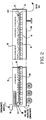
- Figure 2 is a schematic representation of a trailer housing a thermal desorption unit having a conveyor belt;
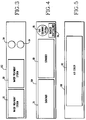
- Figure 3 is a schematic representation of a trailer housing a water treatment system;
- Figure 4 is a schematic representation of a trailer housing a gas treatment system; and
- Figure 5 is a schematic representation of a trailer housing a recycle water cooling system.
- The invention described herein provides an apparatus and method for thermally desorbing contaminants from contaminated solid materials, thereby separating the volatile contaminants from the solid materials.
- A thermal desorption unit, referred to generally as 10, is capable of evaporating water, volatile contaminants, such as PCB's (polychlorinated biphenyls), PHC's (petroleum hydrocarbons), and PCP's (pentachlorophenols), and semi-volatile metals or metallic compounds, such as antimony, lead, cadmium, zinc, or mercury.
- Referring to Figures 1 and 2, the
thermal desorption unit 10 includes achamber 20. Thechamber 20 is a housing, having a plurality of walls, which is substantially airtight. Thechamber 20 has aninlet end 30 for receiving material into thechamber 20 and adischarge end 32 for discharging material from thechamber 20. Thechamber 20 is constructed of mild carbon steel and is insulated with ceramic fiber. To protect the shell from corrosive volatiles, the interior steel surfaces are sprayed with a corrosion resistant material before installing the insulation, and a stainless steel vapor barrier, which may include an additional layer of fiber insulation, is positioned adjacent to the ceramic fiber. - The
chamber 20 houses abelt conveyor 36, which may be constructed from a metal alloy or ceramic cloth, for transporting the contaminated material through thechamber 20. Thebelt conveyor 36, which is supported onrollers 38, has anupper belt portion 40 for moving the material from theinlet end 30 to the discharge end 32 of thechamber 20 and alower belt portion 42 positioned below theupper belt portion 38. A rotary drier, such as a rotary kiln or rotating drum, cannot be substituted for thebelt conveyor 36 due to the variable residence time of the material within the rotary drier, the limited heat transfer rates, the limited range of temperatures of the material, and the aeration of particulates within the volatilized contaminants. - Positioned within the
chamber 20 are turning bars (not shown) with an array of attached teeth which slowly rake through the material layer positioned on thebelt conveyor 36 as the material moves through thechamber 20, for increasing contaminant removal. The plurality of turning bars are positioned along the length of thebelt conveyor 36 with the teeth positioned so that all of the material is turned as it moves along the length of thebelt conveyor 36. The turning bars turn the material to ensure that all of the contaminants are exposed to the heat, but do not create particulates floating in the space above thebelt conveyor 36. - The turning bars do not disturb the rate of movement of the material on the
conveyor belt 36 as compared to a rotary kiln. A rotary kiln overturns the material creating the possibility of a portion of the material progressing through the chamber at a different rate than the rate of progress of another portion of the material progressing through the chamber. A consistent rate of movement of the contaminated material through thechamber 20 on thebelt conveyor 36 enables a known residence time to be determined, as compared to the variable amount of time that a particular portion of material remains within a rotary kiln. By knowing the residence time needed for effective volatilization of a particular contaminant at a certain temperature, the length of time the material is held within thechamber 20 is minimized, thereby increasing the throughput of the material through thethermal desorption unit 10. - A plurality of
heaters 50 are positioned above thebelt conveyor 36 for heating the material as the material moves through thechamber 20 on thebelt conveyor 36. Theheaters 50 may be infrared heaters, radio frequency heaters, or microwave heaters. The utilization of these heaters allows very high temperatures to be obtained in the contaminated material because heat transfer surfaces and their materials of construction are not a consideration. Preferably, infrared heaters are utilized, thereby enabling the material to be directly heated by convection and conduction and indirectly heated by radiation. Because the material moves through thechamber 20 at a constant rate and because the requisite temperatures can be obtained by utilization of thebelt conveyor 36, the residence time of the contaminated material in thechamber 20 can be precisely controlled. - While the required oxygen concentrations and residence time of the material within the
chamber 20 are maintained, theheaters 50 are capable of heating the contaminated material to a temperature effective to volatilize the contaminants, without incinerating or pyrolyzing the contaminants. Theheaters 50 heat the material to a temperature between the range of approximately 212°F (100°C) to 1250°F (680°C) for volatilizing the contaminants from the solid material. Preferably, the material is heated to at least about 850°F (450°C) for a PCB contaminated material. Theheaters 50 are connected to a control panel (not shown) for supplying and controlling electric power to theheaters 50. - The
chamber 20 is substantially airtight for preventing air from entering thechamber 20. Reducing the quantity of air within thechamber 20 reduces the possibility of volatilized contaminants leaking from thechamber 20 into the atmosphere. By preventing air from entering thechamber 20, there is a smaller volume of gas circulation within thechamber 20, which minimizes dust and particulate materials flowing above thebelt conveyor 36, thereby increasing the efficiency of removal of the volatilized contaminants. Also, because the conditions necessary for incineration are a combination of the quantity of air, the temperature, and the residence time within thechamber 20, the prevention of air from thechamber 20 reduces the possibility of incineration of the contaminants, thereby minimizing the formation of highly toxic combustion products, such as dioxins and dibenzofurans. - A
feed conveyor 52 moves the contaminated material from a supply source, such asdryer 54, to afeed hopper 56, which is positioned adjacent to theinlet end 30 of thechamber 20. Thefeed hopper 56 may have a plurality of screw conveyors (not shown) rotatably mounted within an elongated housing, for moving the contaminated material into thechamber 20. The screw conveyors filled with the contaminated material act as a seal and prevent air from entering thechamber 20. - A
conveyor 58 positioned adjacent to the discharge end 32 of thechamber 20 removes the substantially decontaminated processed material from thechamber 20. - The
chamber 20 has agas inlet duct 62 for passing a flow a gas into thechamber 20 countercurrent to the movement of the contaminated material through thechamber 20. The transport gas will carry the volatilized contaminants from the discharge end 32 of thechamber 20 towards theinlet end 30 of thechamber 20. Preferably, the gas will flow above the contaminated material positioned on thebelt conveyor 36. By preventing the flow of gas through the contaminated soil, the presence of dust and fines above thebelt conveyor 36 will be reduced, thereby decreasing the amount of contaminated waste produced by the process. The countercurrent flow of the transport gas has a velocity sufficient to sweep the contaminants from thechamber 20, such as a velocity of approximately 0.2 ft/sec (0.06 m/sec) to 2.5 ft/sec (0.75 m/sec). The gas carrying the contaminants is discharged from thechamber 20 through agas outlet duct 64 positioned near theinlet end 30 of thechamber 20. - The
dryer 54, which is optional, is used to evaporate water from the contaminated material prior to the contaminated material entering thechamber 20. By removing the water prior to thermal desorption, the quantity of heat and residence time required within thechamber 20 to desorb the contaminants is less than that required to desorb the contaminants and the water within thechamber 20. - The processed material discharged from the
chamber 20 is quenched with water for cooling the material. The steam produced by the quenching may be recirculated through the system by passing the steam into thechamber 20 as the transport gas for carrying the volatilized contaminants from thechamber 20. Preferably, the steam is not admitted into thechamber 20 until the temperature of the outlet soil from thechamber 20 is greater than 212°F (100°C) for preventing the steam from condensing on the soil surface. Alternatively, nitrogen or carbon dioxide may be used as the gas for carrying the volatilized contaminants from thechamber 20. - A
qencher 70 is positioned adjacent to thechamber 20 for condensing the gas exiting from thegas outlet duct 64 of thechamber 20. Preferably, a direct, water spray contact condenser is utilized. Water is sprayed into the gas mixture in theqencher 70 to produce a water saturated gas. The gas may be quenched to a temperature of approximately 212°F (100°C) or lower. By condensing the gas, as compared to incineration of the gas, the liquid condensate may be easily transported to another site for further processing. Also, the use of a quencher to process the volatilized contaminants does not produce toxic by-products, as is produces by incineration of the volatilized contaminants. - Still referring to Figure 1, a
scrubber 80 is positioned adjacent to thequencher 70 for removing particulates from the water saturated gas. When a high pressure spray impacts the gas within thescrubber 80, the particulates attach to droplets of water. The particulates, including the contaminants, are removed from thescrubber 80 separately from the removal of gas from thescrubber 80. - As an example, a Calvert Collision Scrubber from Calvert Inc. may be utilized as the
scrubber 80. Gas entering the Calvert Collision Scrubber is split into two gas streams prior to entering the primary atomization zones, similar to venture scrubber throats. The drops of water collect particles as the drops of water are accelerated toward the collision zone in the center of the throat. In the collision zone, the drops of water, because of their inertia, travel into the opposing gas stream, where the drops attain in a relative velocity twice that in the primary atomization zone. This collision process shreds the water drops into fine drops, which more effectively collect submicron particles and produce a large mass transfer area for gas absorption. The substantially particulate-free gas stream flows to a de-entrainment section, where liquid droplets are removed, for separating the liquid from the gas. - The scrubbed gas is drawn from the
scrubber 80 by an induceddraft blower 84. A portion of the gas is passed through agas cleaning system 86, such as a stack with activated carbon, which provides an additional organic contaminant removal step. A portion of the gas may be recycled by passing the gas into thechamber 20 as the transport gas. - The water removed from the
scrubber 80 is passed to awater treatment system 90, such as an oil/water separator. Thewater treatment system 90 removes contaminants, such as PCB and PHC, and soil fines. The contaminants discharged from thewater treatment system 90 may be sent to an incineration facility for further processing. - A portion of the treated water is passed through an
air cooler 92 and returned to thequencher 70, for cooling the gas outlet stream fromchamber 20. Theair cooler 92 may comprise an indirect, water cooled spray tower or dry cooling system. - A portion of the treated water is passed through a
residual treatment system 94, which may include activated carbon, ion exchange, precipitation and flocculation, for providing an additional treatment process for the water. The water passed through theresidual treatment system 94 is recycled by using the water to quench the processed soil exiting thechamber 20. - A control system (not shown) houses the controls required to operate the subsystems of the thermal desorption process. A control cabinet (not shown) houses the system alarms, annunciators, recorder, process controllers, and process indicators.
- As an example, the hourly throughput for the thermal desorption process is at least about 1 ton (900 kg) per hour of soil. Preferably, the throughput is at least about 10 tons (9,000 kg) per hour. The
thermal desorption unit 10 permits at least approximately 15 tons (13,600 kg) per hour throughput of soil. The residence time of the soil in thechamber 20 of thethermal desorption unit 10 is within the range of approximately five minutes to 60 minutes. - As an illustration, the estimated final PCB levels achievable utilizing the thermal desorption unit and process are approximately 1 ppm or less. To effectively remove PCB's, the contaminated material is heated to above approximately 850°F (450°C) with a residence time of approximately two to 20 minutes at approximately 850°F (450°C). As an example, approximately 20,700 lb/hr (9,400 kg/hr) of soil contaminated with PCB's can be processed in the
chamber 20 at a temperature of approximately 950°F (510°C) and a residence time of approximately 6 minutes. PCB's are used for illustration only. Organics, volatile metals, and their salts can also be removed. - The capacity of the thermal desorption system is dependent upon the characteristics of the feed material. The feed capacity is primarily determined by the contaminant desorption rates, the thermal conductivity, and the percent moisture of the feed. Other important variables are heat capacity of the bed of contaminated material, thermal conductivity of the bed, density of the soil, and absorptivity of the soil.
- Contaminated material may be transported from a contamination site to a permanent facility housing the
thermal desorption unit 10. Alternatively, thethermal desorption unit 10 may be transported to the contamination site for on site processing of the contaminated material. - The description and arrangement of several of the components utilized in the thermal desorption process, such as the
heaters 50 and thebelt conveyor 36, are described in U.S. Patent 4,050,900. - Referring to Figure 2, the
chamber 20 of thethermal desorption unit 10, thefeed hopper 56, thebelt conveyor 36, and theheaters 50 are housed on afirst trailer 100. - Referring to Figure 3, a
second trailer 102 houses a plurality of thewater treatment systems 90 and a plurality of thecarbon absorption columns 94. - Referring to Figure 4, a
third trailer 104 houses thequencher 70, thescrubber 80, the induceddraft blower 84, and thegas cleaning system 86. - Referring to Figure 5, a
fourth trailer 106 houses theair cooler 92. Various other pieces of equipment, such as transformers, pumps, and the control system, may be housed on additional trailers (not shown). - Preparation equipment (not shown) processes the contaminated material to produce a feed stream with individual pieces smaller than 1 inch. Referring to Figures 1 and 2, after processing, the contaminated material is placed through
stream 110 into aweigh hopper 111, which maintains a constant feed rate of contaminated material tochamber 20. - The use of
dryer 54 is optional. If the contaminated material is conveyed from theweigh hopper 111 into thechamber 20, theheaters 50 within thechamber 20 will evaporate the water from the contaminated material prior to thermally desorbing the contaminants. If the contaminated material is conveyed from theweigh hopper 111 to thedryer 54 throughstream 112, then the contaminated material is heated within thedryer 54, which evaporates the water from the contaminated material. By removing the water prior to entry of the contaminated material into thechamber 20, less energy is needed to thermally desorb the contaminants from the material and the residence time of the contaminated material within thechamber 20 is reduced. Because the contaminated material may be a wet sludge, which may clog the screw conveyors of thefeed hopper 56, by drying the contaminated material in thedryer 54 prior to entry of the material into thechamber 20, the wet sludge is converted to separate fragments of material, which do not clog thefeed hopper 56. Also, the dried material is more readily handleable, than the wet sludge. - The contaminated material is conveyed to the
feed hopper 56 on thefeed conveyor 52, which is substantially enclosed. The contaminated material falls through the opening in the top of thechamber 20 and forms a one to two inch (2.5 to 5 cm) layer across the width of thebelt conveyor 36. - The
chamber 20 of the infraredthermal desorption unit 10 operates at a slight vacuum, such as about 0.1 inch (0.2 cm) of water, for reducing the leakage of volatilized contaminants from thechamber 20 into the atmosphere. The contaminated material is heated by theheaters 50 as the material moves through thechamber 20 positioned on thebelt conveyor 36. The material will be heated to a temperature effective to volatilize the contaminants from the soil, such as within the range of 212°F (100°C) to 1250°F (680°C). - A flow of gas through
stream 113 enters thechamber 20 through thegas inlet duct 62 and transports the volatilized contaminants countercurrent to the flow of the contaminated material on thebelt conveyor 36 above thebelt conveyor 36. The gas and the volatilized contaminants exit thechamber 20 through thegas outlet duct 64. - The vapor product off-gas including the gas and the volatilized contaminants passes through
stream 114 to thequencher 70, which provides a cold water shower for lowering the temperature of the gas to below its saturation point to condense the vapor product off-gas. From thequencher 70, the gas stream passes throughstream 116 to thescrubber 80, which uses water droplet contact for removing solids and contaminants from the gas stream. A gas stream and a contaminated liquid condensate will exit from thescrubber 80. - The cleaned gas stream is drawn through
stream 118 by the induceddraft blower 84 from thescrubber 80. A portion of the cleaned gas stream may pass throughstream 120 for entry into thechamber 20 through thegas inlet duct 62 for recycling the gas. The remainder of the cleaned gas stream passes throughstream 122 into thegas cleaning system 86 for an additional cleaning step prior to discharge into the atmosphere. - The contaminated liquid condensate passes through
stream 124 into thewater treatment system 90 for removal of an oil contaminant sludge phase using gravitational settlement. The cleaned water may also be additionally treated by flocculation, gravity settling, or carbon absorption to remove the remainder of the contaminants. The oil sludge and absorbed contaminants are passed throughstream 126 and are removed from the site for further processing. - The decontaminated water passes through
stream 128 and a portion of the decontaminated water is passed throughstream 130 into theair cooler 92 and then throughstream 132 into thequencher 70 for recycling the water. A portion of the decontaminated water is passed throughstream 134 into theresidual treatment system 94 for removing residual organics and metals and then passed throughsteam 136 for quenching the clean soil exiting thechamber 20 for recycling the water. - Clean soil drops off the end of the
belt conveyor 36 and onto theconveyor 58, exiting thethermal desorption unit 10 through the discharge end 32 of thechamber 20. After the quenching of the clean soil discharged from thechamber 20 to lower the temperature of the soil, the soil is returned to the environment. At least a portion of the steam produced by quenching the clean soil is recycled by passing the steam into thechamber 20 as the transport gas. - Therefore, the invention provides an apparatus and method for removing volatile contaminants from contaminated soil by heating the contaminated material under oxygen concentrations, temperature conditions, and residence time effective to thermally desorb the contaminants from the material without incinerating the contaminants.
IDENTIFICATION OF REFERENCE NUMERALS USED IN THE DRAWINGS LEGEND REF. NO. FIGURE THERMAL DESORPTION UNIT 10 1 DRYER (OPTIONAL) 54 1 QUENCHER 70 1 QUENCHER 70 4 SCRUBBER 80 1 SCRUBBER 80 4 INDUCED DRAFT BLOWER 84 4 GAS CLEANING SYSTEM 86 4 WATER TREATMENT SYSTEM 90 1 WATER TREATMENT SYSTEM 90 3 AIR COOLER 92 1 AIR COOLER 92 5 CARBON ABSORPTION COLUMN 94 1 WEIGH HOPPER 111 1
Claims (12)
- A method for removing contaminants from contaminated material, comprising the steps of:moving the contaminated material positioned on a belt conveyor through a chamber from an inlet end of the chamber to a discharge end of the chamber;heating the contaminated material positioned on the belt conveyor in the chamber as the contaminated material moves through the chamber to a temperature effective for volatilizing the contaminants and for producing a processed material that is substantially decontaminated;maintaining the temperature, oxygen concentrations, and residence time effective to substantially avoid incineration of the contaminants;passing a transport gas through the chamber for carrying volatilized contaminants from chamber;discharging the transport gas and the volatilized contaminants from the chamber;condensing at least a portion of the volatilized contaminants discharged from the chamber for producing a condensate;discharging the processed material from the chamber through the discharge end of the chamber, the method being characterised by :scrubbing the gas mixture containing the transport gas and the volatilized contaminants which exit from the chamber to produce a scrubbed gas and a contaminated liquid condensate;treating the contaminated liquid concentrate in a water treatment system for separating the organic contaminants from the contaminated liquid condensate and from the water used in cooling the gas mixture during scrubbing of the gas mixture;cooling at least a portion of the water in an air cooler to produce cooled water; andrecycling at least a portion of the cooled water by utilizing the cooled water for condensing the volatilized contaminants.
- The method according to claim 1, wherein the step of heating the contaminated material is characterized by infra-redly heating the contaminated material.
- The method according to claim 1, wherein the transport gas utilized for carrying the volatilized contaminants from the chamber is steam produced by quenching the processed material discharged from the chamber.
- The method according to claim 1, further characterized by the step of substantially preventing air from entering the chamber to minimize the formation of highly toxic combustion products.
- The method according to claim 1, further characterized by the step of drying the contaminated material prior to entry of the contaminated material into the chamber to remove water from the contaminated material.
- The method according to claim 5, wherein at least 5 to 15 tons (4,500 to 13,600 kg) of contaminated material is processed per hour on the belt conveyor after drying the contaminated material to remove moisture from the material prior to the material entering the chamber.
- The method according to claim 1, wherein the contaminated material is heated to a temperature within the range of 212°F (100°C) to 1250°F (680°C) for volatilizing the contaminants.
- The method according to claim 1, wherein the step of heating contaminated soil is characterized by heating the contaminated soil to a temperature greater than 850°F (450°C) for volatilizing PCB from the soil.
- The method according to claim 1, further characterized by the step of recycling the scrubbed gas by introducing at least a portion of the scrubbed gas into the chamber as the transport gas.
- The method according to claim 9, further characterized by the steps of treating at least of portion of the water in a residual treatment system to remove residual contaminants from the water and to produce treated water and recycling the treated water by utilizing at least a portion of the treated water to quench the processed material exiting the chamber.
- An apparatus for removing volatile and semi volatile contaminants from contaminated materials, comprisinga chamber (20) having an inlet end (30) and a discharge end (32);a belt conveyor (36) for moving the contaminated material through the chamber (20) from the inlet end (30) of the chamber (20) to the discharge end (32) of the chamber (20);at least one heater (50) positioned within the chamber (20) above the belt conveyor (36) for heating the contaminated material positioned on the belt conveyor (36) as the contaminated material moves through the chamber (20) for volatilizing the contaminants and for producing a processed material;means for maintaining oxygen concentrations, temperature, and time conditions effective to substantially avoid incineration of the contaminants;means for passing a transport gas above the contaminated material positioned on the belt conveyor (36) for carrying the volatilized contaminants from the chamber (20);a quencher (70) positioned at one end of the chamber (20) for condensing at least a portion of the volatilized contaminants discharged from the chamber (20);a scrubber (80) positioned adjacent to the quencher for removing contaminants from the gas mixture of transport gas and volatilized contaminants, to provide a contaminated liquid condensate;a water treatment system (90) positioned adjacent to the scrubber for separating organic contaminants from the contaminated liquid condensate; and a cooler (92) positioned adjacent to the water treatment system (90) to cool at least a portion of the liquid condensate, and a conduit to pass said cooled liquid to the quencher (70) for condensing volatilized contaminants.
- The apparatus according to claim 11, further characterized by a dryer (54) positioned adjacent to the conveyor (36) for drying the contaminated material to remove water prior to entry of the contaminated material into the chamber (20).
Applications Claiming Priority (2)
| Application Number | Priority Date | Filing Date | Title |
|---|---|---|---|
| US785397 | 1991-10-30 | ||
| US07/785,397 US5230167A (en) | 1991-10-30 | 1991-10-30 | Removal or organics and volatile metals from soils using thermal desorption |
Publications (3)
| Publication Number | Publication Date |
|---|---|
| EP0540342A2 EP0540342A2 (en) | 1993-05-05 |
| EP0540342A3 EP0540342A3 (en) | 1994-02-09 |
| EP0540342B1 true EP0540342B1 (en) | 1997-03-05 |
Family
ID=25135391
Family Applications (1)
| Application Number | Title | Priority Date | Filing Date |
|---|---|---|---|
| EP92309941A Expired - Lifetime EP0540342B1 (en) | 1991-10-30 | 1992-10-29 | Removal of organics and volatile metals from soils using thermal desorption |
Country Status (5)
| Country | Link |
|---|---|
| US (1) | US5230167A (en) |
| EP (1) | EP0540342B1 (en) |
| JP (1) | JPH05208184A (en) |
| CA (1) | CA2081712A1 (en) |
| DE (1) | DE69217820T2 (en) |
Cited By (2)
| Publication number | Priority date | Publication date | Assignee | Title |
|---|---|---|---|---|
| AU2009238280B2 (en) * | 1998-09-28 | 2013-02-07 | Innova Soil Technology Ltd. | Soil remediation system |
| CN112898996A (en) * | 2021-02-08 | 2021-06-04 | 田园牧歌生态环境科技(江苏)有限公司 | Heating method of carbonization furnace capable of realizing energy-consumption-free cyclic heating |
Families Citing this family (47)
| Publication number | Priority date | Publication date | Assignee | Title |
|---|---|---|---|---|
| US5868940A (en) * | 1991-09-27 | 1999-02-09 | Gurfinkel; Alex | Method for on-site remediation of contaminated natural resources and fabrication of construction products therefrom |
| US5361514A (en) * | 1991-10-30 | 1994-11-08 | Westinghouse Electric Corporation | Removal of volatile and semi-volatile contaminants from solids using thermal desorption and gas transport at the solids entrance |
| DE4220953A1 (en) * | 1992-06-26 | 1994-01-05 | Metallgesellschaft Ag | Process for drying water-containing solids in a fluidized bed |
| US5323662A (en) * | 1992-08-21 | 1994-06-28 | Westinghouse Electric Corporation | Bench scale process and apparatus for determining operating parameters of a thermal desorption process |
| US5514286A (en) * | 1993-10-29 | 1996-05-07 | Etg Environmental | Thermal desorption unit |
| CA2178377A1 (en) * | 1996-06-06 | 1997-12-07 | Janis Avotins | Process and apparatus for the removal of aromatic amines from soil and water |
| DE19632102A1 (en) * | 1996-08-08 | 1998-02-12 | Alexander Czetsch | Bulk solids decontaminated in enclosed heated chamber with integral condenser |
| US5904904A (en) * | 1996-10-31 | 1999-05-18 | Astec Industries, Inc. | Treatment of contaminated particulate material by low-temperature thermal desorption with indirect heating |
| US5988947A (en) * | 1997-11-04 | 1999-11-23 | Bruso; Bruce L. | Multi-section soil remediation device |
| JP3395148B2 (en) | 1998-03-31 | 2003-04-07 | 株式会社豊栄商会 | Soil production method, soil treatment device, treatment method and treatment device |
| US6173508B1 (en) * | 1998-06-08 | 2001-01-16 | Charles Strohmeyer, Jr. | Sewage organic waste compaction and incineration system integrated optionally with a gas turbine power driver exhaust and/or other separate heat source |
| BR0006651A (en) * | 2000-09-13 | 2002-11-05 | Fernando Carvalho De Almeida | Process and equipment for the treatment of waste containing hydrocarbons. |
| US20030147697A1 (en) * | 2002-02-06 | 2003-08-07 | Brady Patrick Richard | Evaporative desorption soil treatment apparatus and process |
| US20040240942A1 (en) * | 2002-05-22 | 2004-12-02 | Richter Roger Todd | Method and system for remediating contaminated soil |
| DE10323774A1 (en) * | 2003-05-26 | 2004-12-16 | Khd Humboldt Wedag Ag | Process and plant for the thermal drying of a wet ground cement raw meal |
| JP2007533940A (en) * | 2003-07-30 | 2007-11-22 | ベーエスハー ボッシュ ウント ジーメンス ハウスゲレーテ ゲゼルシャフト ミット ベシュレンクテル ハフツング | Method for operating a device having at least one partial program stage "drying" |
| US7669349B1 (en) | 2004-03-04 | 2010-03-02 | TD*X Associates LP | Method separating volatile components from feed material |
| US20100035536A1 (en) * | 2005-03-23 | 2010-02-11 | International Business Machines Corporation | Apparatus and method protecting against attack by particulate chemical or biological agents |
| US8065815B2 (en) * | 2006-10-10 | 2011-11-29 | Rdp Technologies, Inc. | Apparatus, method and system for treating sewage sludge |
| US8790496B2 (en) | 2007-03-13 | 2014-07-29 | Heartland Technology Partners Llc | Compact wastewater concentrator and pollutant scrubber |
| US8679291B2 (en) | 2007-03-13 | 2014-03-25 | Heartland Technology Partners Llc | Compact wastewater concentrator using waste heat |
| US8568557B2 (en) | 2007-03-13 | 2013-10-29 | Heartland Technology Partners Llc | Compact wastewater concentrator using waste heat |
| US10005678B2 (en) | 2007-03-13 | 2018-06-26 | Heartland Technology Partners Llc | Method of cleaning a compact wastewater concentrator |
| JP2009208053A (en) * | 2008-03-06 | 2009-09-17 | Toshiba Corp | Method of treating soil |
| JP2009274004A (en) * | 2008-05-14 | 2009-11-26 | Toshiba Corp | Treating method of soil |
| JP5478141B2 (en) * | 2009-08-04 | 2014-04-23 | 株式会社ジー・イーテクノス | Purification device and purification method for soil or sludge contaminated with volatile specified harmful substances |
| GB2485180B (en) * | 2010-11-04 | 2012-09-26 | Chinook Sciences Ltd | Improvements in waste processing |
| US9296624B2 (en) * | 2011-10-11 | 2016-03-29 | Heartland Technology Partners Llc | Portable compact wastewater concentrator |
| US9199861B2 (en) | 2013-02-07 | 2015-12-01 | Heartland Technology Partners Llc | Wastewater processing systems for power plants and other industrial sources |
| JP2016522742A (en) * | 2013-04-29 | 2016-08-04 | リテッロ インコーポレイテッドReterro, Inc. | Soil box for evaporative desorption process |
| JP6044958B2 (en) * | 2013-05-13 | 2016-12-14 | 三菱重工業株式会社 | Dry distillation equipment |
| US9636723B2 (en) * | 2013-09-17 | 2017-05-02 | Reterro, Inc. | High resolution modular heating for soil evaporative desorption |
| CN106001083A (en) * | 2016-07-11 | 2016-10-12 | 佛山科学技术学院 | Organic matter contaminated soil restoring method and device |
| RU2643872C1 (en) * | 2017-02-17 | 2018-02-06 | Общество с ограниченной ответственностью "КВОЛИТИ ГРУП БЕЛГОРОД" | Thermal desorption unit for thermal neutralisation of industrial oil-containing waste |
| KR101820112B1 (en) * | 2017-02-20 | 2018-01-18 | 한국철도기술연구원 | Heat-desorption system of oil-contaminated soil and gravel by indirect irradiation of microwave with prevention device of microwave release and pre-heating device of contaminated soil and gravel using waste heat and heat-desorption method using the same |
| CN106957667B (en) * | 2017-04-19 | 2022-08-26 | 宜都大一重工有限公司 | Microwave chain type slewing machine |
| CN108500046A (en) * | 2018-05-09 | 2018-09-07 | 中国联合工程有限公司 | Contaminated soil thermal desorption device and its method for reducing dioxin generation |
| US11413668B2 (en) | 2018-10-04 | 2022-08-16 | Ezraterra, Llc | Sintered wave multi-media polarity conversion treatment apparatus and process for nondestructive removal and condensation of per- and polyfluoroalkyl substances (PFAS) and other dangerous compounds |
| US10875062B2 (en) | 2018-10-04 | 2020-12-29 | Ezraterra, Llc | Sintered wave porous media treatment, apparatus and process for removal of organic compounds and nondestructive removal and condensation of per and polyfluoroalkyl substances and related fluorinated compounds |
| CN109437435A (en) * | 2018-11-29 | 2019-03-08 | 中冶南方都市环保工程技术股份有限公司 | A kind of organic polluted soil thermal desorption sewage disposal system and method |
| CN109396171A (en) * | 2018-12-17 | 2019-03-01 | 中国计量大学 | The device and method of dystopy and thermal desorption coupling processing contaminated soil in situ |
| CZ202133A3 (en) * | 2021-01-26 | 2022-10-12 | IMPEX TRADE CZ, s.r.o. | Method of decontaminating hazardous substances from solid materials |
| CN114230129A (en) * | 2021-12-16 | 2022-03-25 | 北京华夏安盛科技有限公司 | Oily sludge drying thermal desorption device |
| CN114508902B (en) * | 2022-01-27 | 2023-06-23 | 中国计量大学 | Warehouse type soil drying system for recycling waste heat of secondary combustion chamber and control method |
| US11768189B2 (en) | 2022-02-16 | 2023-09-26 | Patrick Richard Brady | Detection, characterization, and mapping of subsurface PFAS-stabilized viscoelastic non-Newtonian LNAPLS using rheological methods |
| CN114249465B (en) * | 2022-03-02 | 2022-09-30 | 广东工业大学 | Sewage treatment device and method for thermal desorption system |
| CN116412408B (en) * | 2023-06-12 | 2023-08-11 | 河北大美环境修复科技股份有限公司 | Incineration type organic soil treatment device for soil remediation engineering |
Family Cites Families (13)
| Publication number | Priority date | Publication date | Assignee | Title |
|---|---|---|---|---|
| US3432397A (en) * | 1965-02-23 | 1969-03-11 | Clyde H O Berg | Method of retorting solids |
| US4050900A (en) * | 1973-12-10 | 1977-09-27 | Shirco, Ltd. | Incineration apparatus |
| US3954069A (en) * | 1975-03-10 | 1976-05-04 | Myrens Verksted A/S | Process and apparatus for the incineration of aqueous sewage sludge |
| US4756092A (en) * | 1986-09-10 | 1988-07-12 | Habersham Environmental Products | Method and apparatus for drying sludge |
| US4738206A (en) * | 1986-09-16 | 1988-04-19 | Roy F. Weston, Inc. | Apparatus and method for low temperature thermal stripping of volatile organic compounds from soil |
| US4782625A (en) * | 1987-04-03 | 1988-11-08 | Canonie Environmental Services, Inc. | Method of contaminated soil remediation and apparatus therefor |
| DE3734281C2 (en) * | 1987-10-09 | 1994-10-06 | Kurt Von Dr Rer Nat Beckerath | Process for dewatering water-containing and in particular contaminated water-containing sludge and solid aggregates and device suitable therefor |
| US4864942A (en) * | 1988-01-14 | 1989-09-12 | Chemical Waste Management Inc. | Process and apparatus for separating organic contaminants from contaminated inert materials |
| US4977839A (en) * | 1988-01-14 | 1990-12-18 | Chemical Waste Management, Inc. | Process and apparatus for separating organic contaminants from contaminated inert materials |
| US4961391A (en) * | 1989-03-29 | 1990-10-09 | International Technology Corporation | Thermal treatment process for organically contaminated material |
| DE3921591A1 (en) * | 1989-06-30 | 1991-01-03 | Weiss Gmbh & Co Leonhard | METHOD AND DEVICE FOR REMOVING VOLATILE POLLUTANTS FROM EARTH SOILS |
| US4993943A (en) * | 1990-03-02 | 1991-02-19 | Norris David P | Apparatus and method for the removal of higher and lower volatility organic contaminants from soil |
| AU7662691A (en) * | 1990-03-30 | 1991-10-30 | Iit Research Institute | Method and apparatus for treating hazardous waste or other hydrocarbonaceous material |
-
1991
- 1991-10-30 US US07/785,397 patent/US5230167A/en not_active Expired - Fee Related
-
1992
- 1992-10-29 DE DE69217820T patent/DE69217820T2/en not_active Expired - Fee Related
- 1992-10-29 CA CA002081712A patent/CA2081712A1/en not_active Abandoned
- 1992-10-29 EP EP92309941A patent/EP0540342B1/en not_active Expired - Lifetime
- 1992-10-29 JP JP4314065A patent/JPH05208184A/en not_active Withdrawn
Cited By (2)
| Publication number | Priority date | Publication date | Assignee | Title |
|---|---|---|---|---|
| AU2009238280B2 (en) * | 1998-09-28 | 2013-02-07 | Innova Soil Technology Ltd. | Soil remediation system |
| CN112898996A (en) * | 2021-02-08 | 2021-06-04 | 田园牧歌生态环境科技(江苏)有限公司 | Heating method of carbonization furnace capable of realizing energy-consumption-free cyclic heating |
Also Published As
| Publication number | Publication date |
|---|---|
| DE69217820D1 (en) | 1997-04-10 |
| DE69217820T2 (en) | 1997-10-02 |
| US5230167A (en) | 1993-07-27 |
| JPH05208184A (en) | 1993-08-20 |
| CA2081712A1 (en) | 1993-05-01 |
| EP0540342A2 (en) | 1993-05-05 |
| EP0540342A3 (en) | 1994-02-09 |
Similar Documents
| Publication | Publication Date | Title |
|---|---|---|
| EP0540342B1 (en) | Removal of organics and volatile metals from soils using thermal desorption | |
| US5361514A (en) | Removal of volatile and semi-volatile contaminants from solids using thermal desorption and gas transport at the solids entrance | |
| US4977839A (en) | Process and apparatus for separating organic contaminants from contaminated inert materials | |
| EP0894030B1 (en) | Process and apparatus for treating process streams from a system for separating constituents from contaminated material | |
| US6341567B1 (en) | Volatile materials treatment system | |
| US4864942A (en) | Process and apparatus for separating organic contaminants from contaminated inert materials | |
| CA2237291C (en) | Method and apparatus for removing mercury and organic contaminants from soils, sludges and sediments and other inert materials | |
| US5619936A (en) | Thermal desorption unit and processes | |
| US4794871A (en) | Method and installation for the treatment of material contaminated with toxic organic compounds | |
| US4917023A (en) | System for fixing, encapsulating, stabilizing and detoxifying heavy metals in metal-containing sludges, soils, ash and similar materials | |
| US4993943A (en) | Apparatus and method for the removal of higher and lower volatility organic contaminants from soil | |
| JPH09504987A (en) | Combined asphalt plant and soil regeneration system | |
| EP0563482A1 (en) | Method for processing waste comprising drying by sublimation prior to incineration | |
| JPH10503550A (en) | Recycle process of treated wood and equipment to apply the process | |
| US5178077A (en) | Apparatus and method for the removal of higher and lower volatility organic contaminants from soil | |
| CA2122232A1 (en) | Method for treatment of contaminated materials with superheated steam thermal desorption and recycle | |
| EP1015143B1 (en) | Treatment of contaminated soil | |
| US6416567B1 (en) | Removal of mercury from waste materials | |
| US5195887A (en) | Remediation of hydrocarbons from soils, sand and gravel | |
| JP3510300B2 (en) | Waste treatment equipment | |
| JPH0278479A (en) | Method and device for treating incineration ash of waste incineration furnace | |
| AU712838B2 (en) | Volatile materials treatment system | |
| US5501161A (en) | Process for the thermal treatment of solids which arise in the purification of flue gases | |
| JP2004033858A (en) | Apparatus for detoxicating treatment |
Legal Events
| Date | Code | Title | Description |
|---|---|---|---|
| PUAI | Public reference made under article 153(3) epc to a published international application that has entered the european phase |
Free format text: ORIGINAL CODE: 0009012 |
|
| AK | Designated contracting states |
Kind code of ref document: A2 Designated state(s): BE DE FR IT |
|
| PUAL | Search report despatched |
Free format text: ORIGINAL CODE: 0009013 |
|
| AK | Designated contracting states |
Kind code of ref document: A3 Designated state(s): BE DE FR IT |
|
| 17P | Request for examination filed |
Effective date: 19940228 |
|
| 17Q | First examination report despatched |
Effective date: 19950302 |
|
| GRAG | Despatch of communication of intention to grant |
Free format text: ORIGINAL CODE: EPIDOS AGRA |
|
| GRAH | Despatch of communication of intention to grant a patent |
Free format text: ORIGINAL CODE: EPIDOS IGRA |
|
| GRAH | Despatch of communication of intention to grant a patent |
Free format text: ORIGINAL CODE: EPIDOS IGRA |
|
| GRAA | (expected) grant |
Free format text: ORIGINAL CODE: 0009210 |
|
| AK | Designated contracting states |
Kind code of ref document: B1 Designated state(s): BE DE FR IT |
|
| PGFP | Annual fee paid to national office [announced via postgrant information from national office to epo] |
Ref country code: FR Payment date: 19970318 Year of fee payment: 6 |
|
| ET | Fr: translation filed | ||
| REF | Corresponds to: |
Ref document number: 69217820 Country of ref document: DE Date of ref document: 19970410 |
|
| ITF | It: translation for a ep patent filed |
Owner name: MODIANO & ASSOCIATI S.R.L. |
|
| PGFP | Annual fee paid to national office [announced via postgrant information from national office to epo] |
Ref country code: DE Payment date: 19971030 Year of fee payment: 6 |
|
| PGFP | Annual fee paid to national office [announced via postgrant information from national office to epo] |
Ref country code: BE Payment date: 19971105 Year of fee payment: 6 |
|
| PLBE | No opposition filed within time limit |
Free format text: ORIGINAL CODE: 0009261 |
|
| STAA | Information on the status of an ep patent application or granted ep patent |
Free format text: STATUS: NO OPPOSITION FILED WITHIN TIME LIMIT |
|
| 26N | No opposition filed | ||
| PG25 | Lapsed in a contracting state [announced via postgrant information from national office to epo] |
Ref country code: BE Free format text: LAPSE BECAUSE OF NON-PAYMENT OF DUE FEES Effective date: 19981031 |
|
| BERE | Be: lapsed |
Owner name: WESTINGHOUSE ELECTRIC CORP. Effective date: 19981031 |
|
| PG25 | Lapsed in a contracting state [announced via postgrant information from national office to epo] |
Ref country code: FR Free format text: LAPSE BECAUSE OF NON-PAYMENT OF DUE FEES Effective date: 19990630 |
|
| REG | Reference to a national code |
Ref country code: FR Ref legal event code: ST |
|
| PG25 | Lapsed in a contracting state [announced via postgrant information from national office to epo] |
Ref country code: DE Free format text: LAPSE BECAUSE OF NON-PAYMENT OF DUE FEES Effective date: 19990803 |
|
| PG25 | Lapsed in a contracting state [announced via postgrant information from national office to epo] |
Ref country code: IT Free format text: LAPSE BECAUSE OF NON-PAYMENT OF DUE FEES Effective date: 20051029 |