EP0539983A1 - Device for changing web rolls automatically - Google Patents
Device for changing web rolls automatically Download PDFInfo
- Publication number
- EP0539983A1 EP0539983A1 EP92118508A EP92118508A EP0539983A1 EP 0539983 A1 EP0539983 A1 EP 0539983A1 EP 92118508 A EP92118508 A EP 92118508A EP 92118508 A EP92118508 A EP 92118508A EP 0539983 A1 EP0539983 A1 EP 0539983A1
- Authority
- EP
- European Patent Office
- Prior art keywords
- web
- rolls
- roll
- web roll
- supply
- Prior art date
- Legal status (The legal status is an assumption and is not a legal conclusion. Google has not performed a legal analysis and makes no representation as to the accuracy of the status listed.)
- Granted
Links
Images






Classifications
-
- B—PERFORMING OPERATIONS; TRANSPORTING
- B65—CONVEYING; PACKING; STORING; HANDLING THIN OR FILAMENTARY MATERIAL
- B65H—HANDLING THIN OR FILAMENTARY MATERIAL, e.g. SHEETS, WEBS, CABLES
- B65H19/00—Changing the web roll
- B65H19/10—Changing the web roll in unwinding mechanisms or in connection with unwinding operations
- B65H19/12—Lifting, transporting, or inserting the web roll; Removing empty core
- B65H19/123—Lifting, transporting, or inserting the web roll; Removing empty core with cantilever supporting arrangements
-
- B—PERFORMING OPERATIONS; TRANSPORTING
- B65—CONVEYING; PACKING; STORING; HANDLING THIN OR FILAMENTARY MATERIAL
- B65H—HANDLING THIN OR FILAMENTARY MATERIAL, e.g. SHEETS, WEBS, CABLES
- B65H2301/00—Handling processes for sheets or webs
- B65H2301/40—Type of handling process
- B65H2301/41—Winding, unwinding
- B65H2301/413—Supporting web roll
- B65H2301/4132—Cantilever arrangement
- B65H2301/41322—Cantilever arrangement pivoting movement of roll support
- B65H2301/413223—Cantilever arrangement pivoting movement of roll support around an axis parallel to roll axis
-
- B—PERFORMING OPERATIONS; TRANSPORTING
- B65—CONVEYING; PACKING; STORING; HANDLING THIN OR FILAMENTARY MATERIAL
- B65H—HANDLING THIN OR FILAMENTARY MATERIAL, e.g. SHEETS, WEBS, CABLES
- B65H2301/00—Handling processes for sheets or webs
- B65H2301/40—Type of handling process
- B65H2301/41—Winding, unwinding
- B65H2301/415—Unwinding
- B65H2301/41505—Preparing unwinding process
- B65H2301/41508—Preparing unwinding process the web roll being in the unwinding support / unwinding location
- B65H2301/41509—Preparing unwinding process the web roll being in the unwinding support / unwinding location opening web roll and related steps
- B65H2301/415095—Preparing unwinding process the web roll being in the unwinding support / unwinding location opening web roll and related steps gripping an edge of the web, e.g. by clamping and forward it, e.g. to splicing web advancing unit
-
- B—PERFORMING OPERATIONS; TRANSPORTING
- B65—CONVEYING; PACKING; STORING; HANDLING THIN OR FILAMENTARY MATERIAL
- B65H—HANDLING THIN OR FILAMENTARY MATERIAL, e.g. SHEETS, WEBS, CABLES
- B65H2301/00—Handling processes for sheets or webs
- B65H2301/40—Type of handling process
- B65H2301/46—Splicing
- B65H2301/461—Processing webs in splicing process
- B65H2301/4611—Processing webs in splicing process before splicing
- B65H2301/46115—Processing webs in splicing process before splicing by bringing leading edge to splicing station, e.g. by chain or belt
-
- B—PERFORMING OPERATIONS; TRANSPORTING
- B65—CONVEYING; PACKING; STORING; HANDLING THIN OR FILAMENTARY MATERIAL
- B65H—HANDLING THIN OR FILAMENTARY MATERIAL, e.g. SHEETS, WEBS, CABLES
- B65H2301/00—Handling processes for sheets or webs
- B65H2301/40—Type of handling process
- B65H2301/46—Splicing
- B65H2301/461—Processing webs in splicing process
- B65H2301/4615—Processing webs in splicing process after splicing
- B65H2301/4617—Processing webs in splicing process after splicing cutting webs in splicing process
- B65H2301/46172—Processing webs in splicing process after splicing cutting webs in splicing process cutting expiring web only
-
- B—PERFORMING OPERATIONS; TRANSPORTING
- B65—CONVEYING; PACKING; STORING; HANDLING THIN OR FILAMENTARY MATERIAL
- B65H—HANDLING THIN OR FILAMENTARY MATERIAL, e.g. SHEETS, WEBS, CABLES
- B65H2301/00—Handling processes for sheets or webs
- B65H2301/40—Type of handling process
- B65H2301/46—Splicing
- B65H2301/462—Form of splice
- B65H2301/4621—Overlapping article or web portions
Definitions
- This invention relates to a device for automatically mounting web rolls each having a core and a belt-like thin sheet or a web wound therearound, used in an apparatus for taking off the web from each of the web rolls, and more particularly to a web changing device for automatically replacing, with a new web roll, the used web roll mounted in a web supplying apparatus for continuously taking off webs from paper web rolls and supplying the webs to the web changing device.
- the web supplying apparatus is used in a machine for manufacturing cigarette rods, filter rods and the like, which are intermediate products of cigarettes.
- belt-like paper sheets are wound around cigarette material to form elongated cigarette rods, and thereafter the rods are cut into pieces each having a predetermined length.
- belt-like paper sheets are also wound around filter sheets made of fiber or the like to form elongated filter rods and thereafter the filter rods are cut into pieces each having a predetermined length.
- Such a web is usually supplied in a form of a web roll comprising a core and a web wound around a roll, as shown in Fig. 7.
- the web roll is mounted in a web supplying apparatus and the web is continuously taken off from the web roll and is supplied therefrom to the succeeding apparatus.
- a web is taken off from a new web roll and the leading end of the new web is connected to the trailing end of the web from the old web roll. In such a way, webs are supplied continuously.
- This invention provides an automatic web roll changing device which can change web rolls automatically in an apparatus for supplying webs continuously, which can store and hold a great number of web rolls and which allows the webs continuously for a long time by automatically changing web rolls to be supplied for a long time without help of the operator.
- the device of this invention supplies webs to a web supply-connection apparatus which takes off a web from a web roll and supply the web and, when the web in the web roll is fully used, takes off the web from a new web roll and automatically connects the both webs from the old and new web rolls thereby supplying the webs continuously.
- This device has a web storage-mounting unit which stores a plurality of new web rolls and automatically mounts the new web rolls in the web supply-connection apparatus.
- a rotary arm is pivoted at its center to the web supply-connection apparatus.
- Two hubs, on which web rolls are mounted, are provided on both ends of the rotary arm.
- the web storage-mounting unit is disposed opposed to the web supply-connection apparatus and comprises a rotary head rotatably in a horizontal plane from the rotary head, for slidably holding a plurality of web rolls in such a way that the web rolls are arranged axially, and a driving mechanism for forwardly moving the web rolls held on the web roll storing shaft.
- the web roll storing shaft is coaxially aligned with one of the hubs of the rotary arm of the web supply-connection apparatus.
- the web supply-connection apparatus takes off and supplies the web from the other web rolls (hereinafter referred to as "the first web roll”).
- the web supply-connection apparatus draws out the web from another web roll (hereinafter referred to as "the second web roll") and automatically connects the leading end of the web on the second web roll to the trailing end of the web of the first web roll.
- the rotary arm is rotated to move the first web roll to the position at which the second web roll was located.
- the hub which carries the first web roll from which the roll has been fully used, faces the web roll storing shaft, and a new web roll held by the web roll storing shaft is mounted on this hub. Every time the web on a web roll is fully used, this process is repeated so that the two hubs on both ends of the rotary arm are supplied with web rolls alternately.
- the web roll storage-mounting unit is provided with a plurality of web roll storage shafts extending from the rotary head. A great number of web rolls are held and stored on these shafts. Once a great number of web rolls are mounted in the web roll storage-mounting unit, the changing operation can continue automatically for a long time without help of the operator.
- the device according to this embodiment is intended to automatically and continuously supply webs to machines for manufacturing cigarette rods, filter rods and the like via a web supply-connection apparatus.
- This device has a web roll storage-mounting unit for mounting web rolls on the web supply-connection apparatus automatically.
- a web roll 1 used in the device according to this invention will now be described with reference to Fig. 7.
- the web roll 1 comprises a core 3 and a web 2 wound therearound.
- the leading end portion of the web 2 is temporarily attached to the body of the web 2 by an adhesive tape 4 which has such a weak adhering force that the leading end of the web 2 is easily detached from the body of the web 2.
- the part of the leading end portion of the web 2 between the leading edge thereof and the adhesive tape 4 forms a detaching part 5 having a length of about 4 to 5 mm.
- a web supply-connection apparatus is designated at 100 and is adapted to continuously take off and supply a web from the respective web roll 1a and taking off and supply a web from a new web roll 1b when the web on the web roll 1a is fully used.
- the apparatus 100 connects the leading end portion of the web on the web roll 1b to the trailing end portion of the web which was on the web roll 1a.
- the core 3 of the web roll 1a is replaced with a new web roll.
- the process comprising the supply of the webs, the change of the web rolls, the connection of the webs and the replacement of the web rolls is repeated so that the webs are supplied continuously.
- the web 2 is guided by guide rails 302 and supplied from the web supply-connection apparatus 100 to, for example, a cigarette rod manufacturing apparatus 300 having a reservoir box 302 in which a predetermined length of a portion of a web 2 is stored. While the supply of the web from the respective web roll is temporarily stopped in order to connect the corresponding end portions of the webs, the web portion in the reservoir box 302 is supplied.
- a web roll storage-mounting unit 200 is disposed opposed to the front face of the web roll supply-connection apparatus 100.
- the unit 200 stores and holds a great number of web rolls 1 and automatically mounts the web rolls 1 one by one on the web supply-connection apparatus 100 when the web on a web roll is fully used.
- a control unit 400 has a control panel and control circuits for controlling the operation of the overall device.
- the main body of the apparatus 100 is designated at 101 in the figure.
- a rotary arm 102 which is rotatable in a horizontal plane about a central rotary shaft 103.
- hubs 104a and 104b On both ends of the rotary arm 102 are provided hubs 104a and 104b on which web rolls 1 are mounted.
- a web 2a is being taken off from a web roll 1a mounted on the right-side hub 104a, and a web roll 1b on which a web is fully wound and which is mounted on the left-side hub 104b is in a waiting state.
- the web 2 taken off from the right-side web roll 1a is guided by a plurality of rollers and supplied to the cigarette manufacturing apparatus 300 through the guide rails.
- a drawing-out mechanism 105 is provided under the web rolls and has a drawing-out arm 106 which is rotatable in a vertical plane, moved vertically by a lifting mechanism 108 and also moved back and forth.
- a chucking mechanism 107 is provided on the front end of the drawing-out arm 106.
- the front end of the drawing-out arm 106 abuts against the lowest surface portion of this web roll 1b which is in the waiting state, and the chucking mechanism 107 catches the detaching part 5 of the web 1b.
- the drawing-out arm 106 rotates downward to the vertical position, the web 2 is drawn out, and the arm 106 is lowered by the lifting mechanism 108 to the position shown by two-dotted lines in Fig. 3.
- a feed mechanism 109 is pivoted at its lower end to the lower portion of the front face of the main body 101 and is rotated by a cylinder 113 in a vertical plane.
- the feed mechanism 109 has an endless sucking belt which is formed with a great number of holes and whose inner pressure is rendered negative. After having been rotated to the vertical position shown by the two-dot lines in Fig. 3, the feed mechanism 109 sucks the leading end of the web 2 held by the drawing-out arm 106 and receives the web 2. Thereafter, the sucking belt is moved so as to send the leading end of the web down-ward.
- An adhesive tape supplying mechanism 110 is also provided on the front face of the main body 101.
- An adhesive tape such as a both-side adhering type adhesive tape is attached by the adhesive tape supplying mechanism 110 to the leading end portion of the web which the feed mechanism 109 is sucking.
- the web to which the adhesive tape has been attached is further moved downward by the feed mechanism 109 and overlaps with the vertically running portion of the web roll 1 which has already been taken off. Then, the previously taken-off web stops and is pressed by a pushing mechanism 111 against the leading end portion of the web which is being taken off so that both webs are connected by the adhesive tape.
- a cutting mechanism 112 and a chucking mechanism 14 are provided on the lower portion of the main body 101. After the leading end portion of the web, which is being drawn out, has been held and provided with a predetermined tension by the chucking mechanism 114, this web is cut at the portion just ahead of the adhesive tape by the cutting mechanism 112 and the excess portion of the leading end portion of this web is removed.
- the portion of the previously drawn-out web which is the just rear portion of the adhesive tape is also cut by a cutter provided on the pushing mechanism 111.
- the leading end portion of the web which is being drawn out from the web roll 1b and the tailing end portion of the already drawn-out web are connected by the adhesive tape.
- the rotary arm 102 rotates through 180° and the web roll 1b from which the web is being taken off is moved to the right side.
- the core of the web roll 1a from which the web has been taken off is removed from the hub 104a and the hub 104a from which the core has been removed (hereinafter referred to as "the free hub") is moved leftward.
- the general structure of the web storage-mounting unit 200 will now be described with reference to Fig. 4.
- the unit 200 has a main body 201 which is provided with a moving table 202 movable toward and away from the web supply-connection apparatus 100.
- a nut member 205 is provided on the moving table 202 and engages a screw shaft 204 rotated by a motor 203 in a normal direction and in the opposite direction thereto.
- a rotary head 206 is provided on the moving table 202 so as to rotate in a horizontal plane.
- a plurality of web roll storing shafts extend vertically from the rotary shaft 206 so that they are separated by the same angle from one after another.
- two web roll storing shafts 207a and 207b extend from the rotary shaft 206 in the opposite directions so that they are separated by 180° from each other.
- a great number of web rolls 1 are axially slidably mounted on the web roll storing shafts 207a and 207b.
- Each web roll storing shaft has a pushing-out mechanism 208. The mechanism 208 moves axially of the respective web roll storing shaft and moves the web rolls 1 held on the web roll shaft to push out them one by one from the front end of the shaft.
- the moving table 202 of the web roll storage-connection unit 200 is moved together with the rotary head 206 and the web roll storing shafts 207a and 207b until the front end of the web roll storing shaft 207a abuts against the front end of the free hub.
- the pushing-out mechanism 208 pushes out a web roll 1 held by the web roll storing shaft facing the web supply-connection apparatus 100 and then mount the same on the free hub.
- This process is repeated in such a way that, when the roll on the operating web roll is going to be fully used, a new web is drawn from the web roll which was in a waiting state so that the leading end portion of the new web is connected to the trailing end portion of the previously drawn-out web, whereby the webs are continuously supplied and a new web roll is mounted on the free hub.
- the driving mechanism of the rotary arm 102 and the hubs 104a and 104b will now be described with reference to Fig. 5.
- the rotary shaft 103 to which the central portion of the rotary arm 102 is pivoted, is rotated by a motor 120 through gears 121 and 122.
- Each of the hubs 104a and 104b is provided with a flange portion 123.
- the hub 104a is connected to a powder brake 140a and a rotary encoder 141a through a pulley 125a, pulleys 126a and 127a rotatable together about the rotary shaft 103, a pulley 131a and belts 129a and 130a.
- the hub 104b is connected to a powder brake 140b and a rotary encoder 141b through a pulley 125b, a pulley 128b rotatable with respect to the rotary shaft 103 and the pulleys 126a and 127a, a pulley 131b and belts 129b and 130b.
- the web is provided with predetermined resistance, i.e., a predetermined tension, the number of rotation, the taken-out length of the web and the like are detected by the respective encoder.
- the powder brakes 140a and 140b and the rotary encoders 141a and 141b are connected to a motor 146 through a connection mechanisms comprising pulleys 142a and 142b, belts 143a and 143b, pulleys 144a and 144b, belts 143a and 143b, pulleys 144a and 144b and clutches 145a and 145b.
- the hubs 104a and 104b are rotated in a normal direction and in the opposite direction, respectively, by the motor 146 through the connection mechanism.
- each of the hubs 104a and 104b is a chucking mechanism (not shown) operated under a pneumatic pressure.
- An air passage is formed in the shaft portion of each of the hubs 104a and 104b.
- Reciprocating air pressure connectors 150a and 150b are provided behind the shafts of the hubs 104a and 104b. As the connectors advance and are connected to the air passages of the hubs 104a and 104b, pneumatic pressure is supplied to the chucking mechanisms of the hubs 104a and 104b and operates the same.
- a core rejecting member 151 which is movable back and forth. As the core rejecting member 151 advances, it passes through a hole formed in the flange portion 123 and pushes the free core (i.e., the core from which the web is drawn out) on the right-side hub 104a to reject the same.
- the web roll storage-mounting unit 200 has the moving table 202 and a cylindrical supporting member 210 projecting upward therefrom.
- the rotary head 206 is rotatably supported on the supporting member 210 by bearings 211, 222 and 223.
- an internal gear 226 which meshes with an external gear 225 driven by a motor 224.
- the rotary head 206 is rotated in a horizontal plane by the motor 224.
- the pushing-out mechanism 208 comprises the hollow web roll storing shafts 207a and 207b and screw shafts 230 coaxially extending through the shafts 207a and 207b and rotatably supported by bearings 233 and 234, respectively.
- the shaft screw 230 is rotated by motors 236a and 236b through bevel gears 237 and 238, respectively.
- nut members 231 Engaged with the screw shafts 230 are nut members 231 which extend out of the web roll storing shafts 207a and 207b through axial slits formed therein.
- a flange member 232 is fixed to each nut member 231.
- the proximal end portion of the pulling-out arm 106 is rotatably mounted on a shaft 501 so that the pulling-out shaft 106 is rotated about the shaft 501 in a vertical plane.
- the chucking mechanism 107 is provided on the distal end portion of the drawing-out arm 107.
- the chucking mechanism 107 comprises a chucking member 502 and a cylinder 503 for opening and closing it.
- a hollow sucking mechanism 505 having a great number of holes formed in its upper surface is provided on the upper surface of the distal end portion of the drawing-out arm 106.
- the interior of the sucking mechanism 505 is connected to a negative-pressure generating mechanism (not shown) for rendering the pressure in the interior of the mechanism 505 negative.
- a leading end portion detector 504 is provided on the distal end portion of the drawing-out arm 106.
- the leading end portion detector 504 is, for example, an optical detector including optical fiber, or the like and is used for detecting the front edge of detaching part 5 of the web of the web roll 1.
- the drawing-out arm 106 When the leading end portion of the web is to be drawn out from the web roll 1b, the drawing-out arm 106 is rotated until it takes a vertical position so that a sucking mechanism 505 provided on its distal end portion abuts against the lowest surface portion of the web roll 1. Since the pressure in the sucking mechanism 505 is negative in this condition, air is introduced from the outer atmosphere into the mechanism 505, whereby the portion of the web which is the outer periphery of the web roll is sucked by the mechanism 505. Then, the web roll is rotated in the direction opposite to the direction in which the web is wound on the core. When the front edge of the detaching part 5 of the web arrives at the chucking mechanism, the leading end portion detector 504 detects the front edge. The chucking member 502 of the chucking mechanism 107 is driven by the cylinder 503 so as to hold the detaching part 5 of the web.
- the drawn-out arm 106 holding the leading end portion of the web is rotated downward until it takes a substantially vertical downward position and the overall drawing-out arm 106 is lowered by the lifting mechanism 108, whereby the web held by the drawing-out arm 106 is pulled out. Since the adhering force of the adhesive tape 4 is weak, the tape 4 is easily detached and the web is not damaged.
- the feed mechanism 109 comprises an elongated hollow main body 510 and pulleys 511 and 512 provided on the upper and lower ends, respectively.
- An endless suction belt 513 is wound on the pulleys 511 and 512.
- the suction belt 513 is formed with a great number of holes so as to provide air-permeability or porosity.
- the suction belt may be made of air-permeable material such as fiber.
- the suction belt 513 is exposed to the outer atmosphere. Air tightness is maintained between both sides of the suction belt 513 and the main body 510.
- the interior of the main body 510 is connected to a negative-pressure generating mechanism (not shown) through a plurality of negative-pressure introducing ports 514 so that the pressure in the main body 510 is maintained negative.
- a holding plate mechanism 520 is fixed to the upper portion of the main body 510 of the feed mechanism 109 and is provided with a holding plate 521 having a smooth surface and connected to an actuator 523 through a spring 522.
- the actuator 523 is fixed to the main body 510 by a fixing plate 524 provided on the front side of the actuator 523.
- the drawing-out arm 106 When the drawing-out arm 106 holds the leading end portion of the web 2b of the new web roll 1b and is moved to the vertical downward position as shown by the two-dot lines in Fig. 3 by pulling out the web 2b, the feed mechanism 109 is moved to the substantially vertical position as shown in Fig. 9, and the suction belt 513 on the upper portion of the feed mechanism 109 abuts against the leading end portion of the web 2b.
- the negative pressure in the main body 510 of the feed mechanism 106 end the porosity of the suction belt 513 allows the suction belt 513 to suck the leading end portion of the web. Then the drawing-out arm 106 is released and the leading end portion of the web is sucked and accurately held by the suction belt 513.
- the web 2b is drawn in a state separated from the suction belt 513 in Fig. 9, but the web 2b closely contacts the suction belt 513 in the real condition.
- the holding plate mechanism 520 operates so that the holding plate 521 is moved by the actuator 523 to cause the leading end portion of the web to closely contact the suction belt 513. In doing so, the web 2b closely contacts the suction belt 513 and is sucked more strongly.
- the suction belt 513 runs and the web 2b is sent downward in a state in which the web 2b is sucked by the suction belt 513.
- the adhesive tape supplying mechanism 110 is provided so as to face the intermediate portion of the feed mechanism 109.
- the mechanism 110 is used to attach the adhesive tape 530 to the leading end portion of the web 2b.
- a leading end portion detector 531 which is, for example, an optical detector for detecting the leading end portion of the web 2b when the web passes the detector 531.
- the adhesive tape supplying mechanism 110 includes an adhesive tape reel 532 from which a composite tape comprising a base paper plate 537 and an adhesive tape 530 of both-surface adhering type attached to the plate 532 is supplied as shown in Fig. 11.
- the composite tape passes on the rollers 533, 534 and 535 and is wound on a tape reel with the adhesive tape 530 disposed outside.
- the roller 533 contacting the adhesive tape 530 is provided with a plurality of ribs 540 each having a sharp outer edge so that the contact area of the ribs 540 with the adhesive tape 530 is made as small as possible to prevent the adhesive tape 530 from being attached to the peripheral surface of the roller 533.
- the cutting mechanism 547 has a cutter 541 connected to a moving member 543 through a spring 542.
- the moving member 543 is fixed to a transverse oscillating actuator 545 and oscillated thereby in the traverse directions of the adhesive tape.
- the transverse oscillating actuator 545 is fixed to a lift actuator 546 which lifts and lowers the transverse oscillating actuator 545, the moving member 543 and the cutter 541 at the same time.
- the cutter 541 is raised by the lift actuator 546 and is in light contact with the adhesive tape 530 by the urging force of the spring 542. Simultaneously, the cutter 541 is oscillated in the transverse directions of the tape by the transverse oscillating actuator 545. In this process, the hard base plate 537 is not cut but only the soft adhesive tape 530 is cut.
- a pressing mechanism 111 is disposed under the adhesive tape supplying mechanism 110. More specifically, the web 2a being taken out is guided by pulleys 560 and 561 and moved vertically in a region between these pulleys.
- the pressing mechanism 111 is provided in this region and comprises a pressing member 552, a pad 553 made of synthetic rubber or the like and provided on the front face of the pressing member 552, and a cutter 554 formed on the upper end of the pressing member 552.
- the pressing member 552 is pressed against the web 2a by an actuator 551.
- the pressing mechanism 111 includes a cutting mechanism 557 for cutting a web 2a which is being drawn out.
- the cutting mechanism 557 has a cutting rod 555 which passes the region close to the cutter 54 on the upper end of the pressing member 552 by means of a driving mechanism including an arm 556.
- the web 2a is caught, pressed against the cutter 554 and cut by the moving cutting rod 555. It is preferred that the cutter 554 take a form of saw teeth in order to cut the web easily.
- a cutting mechanism 112 and a chucking mechanism 114 for cutting the portion of the newly supplied web 2b between the adhesive tape 530 and the leading end edge of the web 2b, i.e., an excess portion of the leading end portion of the web 2b such as the adhesive tape 4 and the detaching part 5 are provided under the pressing mechanism 111.
- the chucking mechanism 114 has a pair of chucks 602 and an actuator 601 which opens and closes the chucks 602.
- the actuator 601 is connected to a lift cylinder 604 by a moving member 603 and moves the cylinder 604 upward and downward.
- the chucks 602 hold the leading end portion of the lowered web 2b and are lowered to give predetermined tension to the web 2b.
- the cutting mechanism 112 includes a pair of cutting members 611 and 612 opened and closed by an actuator 610, for cutting the portion of the web 2b between the cutting members 611 and 612.
- the cutting members 611 and 612 and the actuator 610 are connected to an actuator 614 through an actuator 614 so that they are moved together back and forth.
- the cutting members 611 and 612 are fixed by cutting teeth 615 and 616 and holding members 617 disposed below the respective cutting teeth 615 and 616.
- the holding members 617 are made of elastic material such as synthetic rubber and hold the leading end portion of the cut web 2b therebetween.
- the cutting members 611 and 612, which are holding the leading end portion of the cut web 2b, are moved forward by the actuator 614 to the position above a container for housing the cut portion of the web 2b. Thereafter, the cutting members 617 are separated from each other to release the leading end portion of the web which was held by the cutting members 617 and let the web fall into the container. Therefore, the leading end portion of the web is securely contained in the container and the leading end portion of the cut web is not caught by any part of the device, preventing any trouble due to this catching of the leading end portion.
Landscapes
- Manufacturing Of Cigar And Cigarette Tobacco (AREA)
- Replacement Of Web Rolls (AREA)
- Cigarettes, Filters, And Manufacturing Of Filters (AREA)
Abstract
Description
- This invention relates to a device for automatically mounting web rolls each having a core and a belt-like thin sheet or a web wound therearound, used in an apparatus for taking off the web from each of the web rolls, and more particularly to a web changing device for automatically replacing, with a new web roll, the used web roll mounted in a web supplying apparatus for continuously taking off webs from paper web rolls and supplying the webs to the web changing device. The web supplying apparatus is used in a machine for manufacturing cigarette rods, filter rods and the like, which are intermediate products of cigarettes.
- In the conventional cigarette manufacturing process, belt-like paper sheets are wound around cigarette material to form elongated cigarette rods, and thereafter the rods are cut into pieces each having a predetermined length. Similarly, when filters are manufactured in the conventional process, belt-like paper sheets are also wound around filter sheets made of fiber or the like to form elongated filter rods and thereafter the filter rods are cut into pieces each having a predetermined length.
- Therefore, continuous supply of the above-mentioned belt-like paper pieces, i.e., webs is required for producing cigarette rods and filter rods. Such a web is usually supplied in a form of a web roll comprising a core and a web wound around a roll, as shown in Fig. 7. The web roll is mounted in a web supplying apparatus and the web is continuously taken off from the web roll and is supplied therefrom to the succeeding apparatus. When the web on the web roll is fully used, a web is taken off from a new web roll and the leading end of the new web is connected to the trailing end of the web from the old web roll. In such a way, webs are supplied continuously.
- There has been recently developed a web supplying device which is provided with two web rolls so as to perform these processes automatically. A web is taken off from a first web wheel and is supplied to the succeeding apparatus. When the web on the first web roll is fully used, a web is drawn out from the second web roll which was in a waiting state, and the leading end of the web on the second web roll is automatically connected to the trailing end of the web of the first web rib. Thereafter, the core and other necessary parts are removed from the web supplying apparatus, and a new web roll is mounted thereon. With this web supplying device, this series of web supplying and web replacing processes is repeated so that webs are supplied continuously.
- Since, however, the cigarette manufacturing machine has been operated at a higher speed thereby increasing the amount of webs to be supplied, the web on a web roll is fully used in about ten minutes. In order to replace the used roll with the one new every ten minutes, therefore, an operator must be fully engaged in the replacement work of the web rolls.
- It is very difficult for the operator to endure such a continuous simple work for a long time, and in addition thereto, the manpower cost increases.
- This invention provides an automatic web roll changing device which can change web rolls automatically in an apparatus for supplying webs continuously, which can store and hold a great number of web rolls and which allows the webs continuously for a long time by automatically changing web rolls to be supplied for a long time without help of the operator.
- The device of this invention supplies webs to a web supply-connection apparatus which takes off a web from a web roll and supply the web and, when the web in the web roll is fully used, takes off the web from a new web roll and automatically connects the both webs from the old and new web rolls thereby supplying the webs continuously. This device has a web storage-mounting unit which stores a plurality of new web rolls and automatically mounts the new web rolls in the web supply-connection apparatus.
- A rotary arm is pivoted at its center to the web supply-connection apparatus. Two hubs, on which web rolls are mounted, are provided on both ends of the rotary arm.
- The web storage-mounting unit is disposed opposed to the web supply-connection apparatus and comprises a rotary head rotatably in a horizontal plane from the rotary head, for slidably holding a plurality of web rolls in such a way that the web rolls are arranged axially, and a driving mechanism for forwardly moving the web rolls held on the web roll storing shaft.
- The web roll storing shaft is coaxially aligned with one of the hubs of the rotary arm of the web supply-connection apparatus. The web supply-connection apparatus takes off and supplies the web from the other web rolls (hereinafter referred to as "the first web roll"). When the web is fully used on the first web roll, the web supply-connection apparatus draws out the web from another web roll (hereinafter referred to as "the second web roll") and automatically connects the leading end of the web on the second web roll to the trailing end of the web of the first web roll. At the same time, the rotary arm is rotated to move the first web roll to the position at which the second web roll was located. The hub, which carries the first web roll from which the roll has been fully used, faces the web roll storing shaft, and a new web roll held by the web roll storing shaft is mounted on this hub. Every time the web on a web roll is fully used, this process is repeated so that the two hubs on both ends of the rotary arm are supplied with web rolls alternately.
- The web roll storage-mounting unit is provided with a plurality of web roll storage shafts extending from the rotary head. A great number of web rolls are held and stored on these shafts. Once a great number of web rolls are mounted in the web roll storage-mounting unit, the changing operation can continue automatically for a long time without help of the operator.
- This invention can be more fully understood from the following detailed description when taken in conjunction with the accompanying drawings, in which:
- Fig. 1 is a front view of the overall device according to one embodiment of this invention;
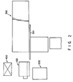
- Fig. 2 is a plant view of the overall device according to this embodiment of this invention;
- Fig. 3 is a pan view of a web supply-connection apparatus;
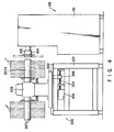
- Fig. 4 is a side view of a web roll storage-mounting unit;
- Fig. 5 is a general plan view of the driving system of a rotary arm and hubs;
- Fig. 6 is a longitudinal cross-sectional view of the main part of the web roll storage-mounting unit;
- Fig. 7 is a perspective view of a web roll;
- Fig. 8 is a front view of a drawing-out arm;
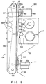
- Fig. 9 is a front view showing the portions of a feed mechanism and an adhesive tape supplying mechanism;
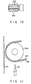
- Fig. 10 is a longitudinal cross-sectional view of a roller;
- Fig. 11 is a front view of the main part of the adhesive tape supplying mechanism;
- Fig. 12 is a side view of the adhesive tape supplying mechanism;
- Fig. 13 is a front view of a pressing mechanism;
- Fig. 14 is a front view of the portions of a cutting mechanism and a chucking mechanism;
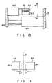
- Fig. 15 is a cross-sectional view taken along line 15-15 of Fig. 14; and
- Fig. 16 is a cross-sectional view taken along line 16-16 of Fig. 15.
- An embodiment of this invention will now be described with reference to the accompanying drawings. The device according to this embodiment is intended to automatically and continuously supply webs to machines for manufacturing cigarette rods, filter rods and the like via a web supply-connection apparatus. This device has a web roll storage-mounting unit for mounting web rolls on the web supply-connection apparatus automatically.
- A web roll 1 used in the device according to this invention will now be described with reference to Fig. 7. The web roll 1 comprises a
core 3 and aweb 2 wound therearound. The leading end portion of theweb 2 is temporarily attached to the body of theweb 2 by an adhesive tape 4 which has such a weak adhering force that the leading end of theweb 2 is easily detached from the body of theweb 2. The part of the leading end portion of theweb 2 between the leading edge thereof and the adhesive tape 4 forms a detachingpart 5 having a length of about 4 to 5 mm. - Referring to Figs. 1 to 4, the overall device according to this invention will now be described. In the figures, a web supply-connection apparatus is designated at 100 and is adapted to continuously take off and supply a web from the respective web roll 1a and taking off and supply a web from a new web roll 1b when the web on the web roll 1a is fully used. The
apparatus 100 connects the leading end portion of the web on the web roll 1b to the trailing end portion of the web which was on the web roll 1a. During the supply of the web from the web roll 1b, thecore 3 of the web roll 1a is replaced with a new web roll. The process comprising the supply of the webs, the change of the web rolls, the connection of the webs and the replacement of the web rolls is repeated so that the webs are supplied continuously. - The
web 2 is guided byguide rails 302 and supplied from the web supply-connection apparatus 100 to, for example, a cigaretterod manufacturing apparatus 300 having areservoir box 302 in which a predetermined length of a portion of aweb 2 is stored. While the supply of the web from the respective web roll is temporarily stopped in order to connect the corresponding end portions of the webs, the web portion in thereservoir box 302 is supplied. - A web roll storage-
mounting unit 200 is disposed opposed to the front face of the web roll supply-connection apparatus 100. Theunit 200 stores and holds a great number of web rolls 1 and automatically mounts the web rolls 1 one by one on the web supply-connection apparatus 100 when the web on a web roll is fully used. - A
control unit 400 has a control panel and control circuits for controlling the operation of the overall device. - The general structure of the web supply-
connection apparatus 100 will now be described with reference to Fig. 3. The main body of theapparatus 100 is designated at 101 in the figure. Provided on the upper portion of the front face of themain body 101 is arotary arm 102 which is rotatable in a horizontal plane about a centralrotary shaft 103. On both ends of therotary arm 102 are providedhubs 104a and 104b on which web rolls 1 are mounted. In the state of Fig. 3, a web 2a is being taken off from a web roll 1a mounted on the right-side hub 104a, and a web roll 1b on which a web is fully wound and which is mounted on the left-side hub 104b is in a waiting state. - The
web 2 taken off from the right-side web roll 1a is guided by a plurality of rollers and supplied to thecigarette manufacturing apparatus 300 through the guide rails. - A drawing-out
mechanism 105 is provided under the web rolls and has a drawing-outarm 106 which is rotatable in a vertical plane, moved vertically by alifting mechanism 108 and also moved back and forth. Achucking mechanism 107 is provided on the front end of the drawing-outarm 106. - After a new web roll 1b has been mounted, the front end of the drawing-out
arm 106 abuts against the lowest surface portion of this web roll 1b which is in the waiting state, and thechucking mechanism 107 catches the detachingpart 5 of the web 1b. while the drawing-outarm 106 rotates downward to the vertical position, theweb 2 is drawn out, and thearm 106 is lowered by thelifting mechanism 108 to the position shown by two-dotted lines in Fig. 3. - A
feed mechanism 109 is pivoted at its lower end to the lower portion of the front face of themain body 101 and is rotated by acylinder 113 in a vertical plane. Thefeed mechanism 109 has an endless sucking belt which is formed with a great number of holes and whose inner pressure is rendered negative. After having been rotated to the vertical position shown by the two-dot lines in Fig. 3, thefeed mechanism 109 sucks the leading end of theweb 2 held by the drawing-outarm 106 and receives theweb 2. Thereafter, the sucking belt is moved so as to send the leading end of the web down-ward. - An adhesive
tape supplying mechanism 110 is also provided on the front face of themain body 101. An adhesive tape such as a both-side adhering type adhesive tape is attached by the adhesivetape supplying mechanism 110 to the leading end portion of the web which thefeed mechanism 109 is sucking. - The web to which the adhesive tape has been attached is further moved downward by the
feed mechanism 109 and overlaps with the vertically running portion of the web roll 1 which has already been taken off. Then, the previously taken-off web stops and is pressed by a pushingmechanism 111 against the leading end portion of the web which is being taken off so that both webs are connected by the adhesive tape. - A
cutting mechanism 112 and a chucking mechanism 14 are provided on the lower portion of themain body 101. After the leading end portion of the web, which is being drawn out, has been held and provided with a predetermined tension by thechucking mechanism 114, this web is cut at the portion just ahead of the adhesive tape by thecutting mechanism 112 and the excess portion of the leading end portion of this web is removed. - The portion of the previously drawn-out web which is the just rear portion of the adhesive tape is also cut by a cutter provided on the pushing
mechanism 111. In this connection, the leading end portion of the web which is being drawn out from the web roll 1b and the tailing end portion of the already drawn-out web are connected by the adhesive tape. - The
rotary arm 102 rotates through 180° and the web roll 1b from which the web is being taken off is moved to the right side. The core of the web roll 1a from which the web has been taken off is removed from the hub 104a and the hub 104a from which the core has been removed (hereinafter referred to as "the free hub") is moved leftward. - After this, a new web roll is mounted on the free hub 104a from the web roll storage-mounting
unit 200. - The general structure of the web storage-mounting
unit 200 will now be described with reference to Fig. 4. Theunit 200 has amain body 201 which is provided with a moving table 202 movable toward and away from the web supply-connection apparatus 100. Anut member 205 is provided on the moving table 202 and engages ascrew shaft 204 rotated by amotor 203 in a normal direction and in the opposite direction thereto. - A
rotary head 206 is provided on the moving table 202 so as to rotate in a horizontal plane. A plurality of web roll storing shafts extend vertically from therotary shaft 206 so that they are separated by the same angle from one after another. In the case of Fig. 4, two webroll storing shafts 207a and 207b extend from therotary shaft 206 in the opposite directions so that they are separated by 180° from each other. A great number of web rolls 1 are axially slidably mounted on the webroll storing shafts 207a and 207b. Each web roll storing shaft has a pushing-outmechanism 208. Themechanism 208 moves axially of the respective web roll storing shaft and moves the web rolls 1 held on the web roll shaft to push out them one by one from the front end of the shaft. - When either one of the web
roll storing shaft 207a and 207b faces the web supply-connection apparatus 100, it is axially aligned with the left-side hub 104b. After the webs have been connected together and the free hub (i.e., the hub from which the core was removed) has been moved leftward by therotary arm 102, the moving table 202 of the web roll storage-connection unit 200 is moved together with therotary head 206 and the webroll storing shafts 207a and 207b until the front end of the web roll storing shaft 207a abuts against the front end of the free hub. In this condition, the pushing-outmechanism 208 pushes out a web roll 1 held by the web roll storing shaft facing the web supply-connection apparatus 100 and then mount the same on the free hub. - This process is repeated in such a way that, when the roll on the operating web roll is going to be fully used, a new web is drawn from the web roll which was in a waiting state so that the leading end portion of the new web is connected to the trailing end portion of the previously drawn-out web, whereby the webs are continuously supplied and a new web roll is mounted on the free hub.
- The driving mechanism of the
rotary arm 102 and thehubs 104a and 104b will now be described with reference to Fig. 5. Therotary shaft 103, to which the central portion of therotary arm 102 is pivoted, is rotated by amotor 120 throughgears hubs 104a and 104b is provided with aflange portion 123. - The hub 104a is connected to a powder brake 140a and a rotary encoder 141a through a pulley 125a, pulleys 126a and 127a rotatable together about the
rotary shaft 103, a pulley 131a and belts 129a and 130a. Thehub 104b is connected to apowder brake 140b and arotary encoder 141b through apulley 125b, apulley 128b rotatable with respect to therotary shaft 103 and the pulleys 126a and 127a, a pulley 131b andbelts - The
powder brakes 140a and 140b and therotary encoders 141a and 141b are connected to amotor 146 through a connection mechanisms comprising pulleys 142a and 142b, belts 143a and 143b, pulleys 144a and 144b, belts 143a and 143b, pulleys 144a and 144b andclutches 145a and 145b. Thehubs 104a and 104b are rotated in a normal direction and in the opposite direction, respectively, by themotor 146 through the connection mechanism. - Provided with each of the
hubs 104a and 104b is a chucking mechanism (not shown) operated under a pneumatic pressure. An air passage is formed in the shaft portion of each of thehubs 104a and 104b. Reciprocating air pressure connectors 150a and 150b are provided behind the shafts of thehubs 104a and 104b. As the connectors advance and are connected to the air passages of thehubs 104a and 104b, pneumatic pressure is supplied to the chucking mechanisms of thehubs 104a and 104b and operates the same. - Behind the right-side hub 104a is provided a
core rejecting member 151 which is movable back and forth. As thecore rejecting member 151 advances, it passes through a hole formed in theflange portion 123 and pushes the free core (i.e., the core from which the web is drawn out) on the right-side hub 104a to reject the same. - As shown in Fig. 6, the web roll storage-mounting
unit 200 has the moving table 202 and a cylindrical supportingmember 210 projecting upward therefrom. Therotary head 206 is rotatably supported on the supportingmember 210 bybearings rotary head 206 is formed aninternal gear 226 which meshes with anexternal gear 225 driven by amotor 224. Therotary head 206 is rotated in a horizontal plane by themotor 224. - The pushing-out
mechanism 208 comprises the hollow webroll storing shafts 207a and 207b and screwshafts 230 coaxially extending through theshafts 207a and 207b and rotatably supported bybearings shaft screw 230 is rotated bymotors 236a and 236b throughbevel gears - Engaged with the
screw shafts 230 arenut members 231 which extend out of the webroll storing shafts 207a and 207b through axial slits formed therein. Aflange member 232 is fixed to eachnut member 231. - As the
screw shafts 230 are rotated by themotors 236a and 236b, thenut members 231 and theflange members 232 are moved axially to push out the web rolls 1. - As shown in Fig. 8, the proximal end portion of the pulling-out
arm 106 is rotatably mounted on ashaft 501 so that the pulling-outshaft 106 is rotated about theshaft 501 in a vertical plane. - The
chucking mechanism 107 is provided on the distal end portion of the drawing-outarm 107. Thechucking mechanism 107 comprises a chuckingmember 502 and acylinder 503 for opening and closing it. A hollow suckingmechanism 505 having a great number of holes formed in its upper surface is provided on the upper surface of the distal end portion of the drawing-outarm 106. The interior of the suckingmechanism 505 is connected to a negative-pressure generating mechanism (not shown) for rendering the pressure in the interior of themechanism 505 negative. - A leading
end portion detector 504 is provided on the distal end portion of the drawing-outarm 106. The leadingend portion detector 504 is, for example, an optical detector including optical fiber, or the like and is used for detecting the front edge of detachingpart 5 of the web of the web roll 1. - When the leading end portion of the web is to be drawn out from the web roll 1b, the drawing-out
arm 106 is rotated until it takes a vertical position so that a suckingmechanism 505 provided on its distal end portion abuts against the lowest surface portion of the web roll 1. Since the pressure in the suckingmechanism 505 is negative in this condition, air is introduced from the outer atmosphere into themechanism 505, whereby the portion of the web which is the outer periphery of the web roll is sucked by themechanism 505. Then, the web roll is rotated in the direction opposite to the direction in which the web is wound on the core. When the front edge of the detachingpart 5 of the web arrives at the chucking mechanism, the leadingend portion detector 504 detects the front edge. The chuckingmember 502 of thechucking mechanism 107 is driven by thecylinder 503 so as to hold the detachingpart 5 of the web. - The drawn-out
arm 106 holding the leading end portion of the web is rotated downward until it takes a substantially vertical downward position and the overall drawing-outarm 106 is lowered by thelifting mechanism 108, whereby the web held by the drawing-outarm 106 is pulled out. Since the adhering force of the adhesive tape 4 is weak, the tape 4 is easily detached and the web is not damaged. - The structure of the
feed mechanism 109 will now be described with reference to Fig. 9. Thefeed mechanism 109 comprises an elongated hollowmain body 510 andpulleys pulleys main body 510, the suction belt 513 is exposed to the outer atmosphere. Air tightness is maintained between both sides of the suction belt 513 and themain body 510. The interior of themain body 510 is connected to a negative-pressure generating mechanism (not shown) through a plurality of negative-pressure introducing ports 514 so that the pressure in themain body 510 is maintained negative. - A holding
plate mechanism 520 is fixed to the upper portion of themain body 510 of thefeed mechanism 109 and is provided with a holdingplate 521 having a smooth surface and connected to anactuator 523 through aspring 522. Theactuator 523 is fixed to themain body 510 by a fixingplate 524 provided on the front side of theactuator 523. - When the drawing-out
arm 106 holds the leading end portion of theweb 2b of the new web roll 1b and is moved to the vertical downward position as shown by the two-dot lines in Fig. 3 by pulling out theweb 2b, thefeed mechanism 109 is moved to the substantially vertical position as shown in Fig. 9, and the suction belt 513 on the upper portion of thefeed mechanism 109 abuts against the leading end portion of theweb 2b. The negative pressure in themain body 510 of thefeed mechanism 106 end the porosity of the suction belt 513 allows the suction belt 513 to suck the leading end portion of the web. Then the drawing-outarm 106 is released and the leading end portion of the web is sucked and accurately held by the suction belt 513. For convenience, theweb 2b is drawn in a state separated from the suction belt 513 in Fig. 9, but theweb 2b closely contacts the suction belt 513 in the real condition. - At the same time, the holding
plate mechanism 520 operates so that the holdingplate 521 is moved by theactuator 523 to cause the leading end portion of the web to closely contact the suction belt 513. In doing so, theweb 2b closely contacts the suction belt 513 and is sucked more strongly. - In this condition, the suction belt 513 runs and the
web 2b is sent downward in a state in which theweb 2b is sucked by the suction belt 513. - The adhesive
tape supplying mechanism 110 is provided so as to face the intermediate portion of thefeed mechanism 109. Themechanism 110 is used to attach theadhesive tape 530 to the leading end portion of theweb 2b. On the upper portion of the adhesivetape supplying mechanism 110 is provided a leadingend portion detector 531 which is, for example, an optical detector for detecting the leading end portion of theweb 2b when the web passes thedetector 531. - As shown in Figs. 9 to 12, the adhesive
tape supplying mechanism 110 includes anadhesive tape reel 532 from which a composite tape comprising abase paper plate 537 and anadhesive tape 530 of both-surface adhering type attached to theplate 532 is supplied as shown in Fig. 11. The composite tape passes on therollers adhesive tape 530 disposed outside. As shown in Fig. 10, theroller 533 contacting theadhesive tape 530 is provided with a plurality ofribs 540 each having a sharp outer edge so that the contact area of theribs 540 with theadhesive tape 530 is made as small as possible to prevent theadhesive tape 530 from being attached to the peripheral surface of theroller 533. - As shown in Fig. 11, only the
adhesive tape 530 disposed outside of the composite tape on theroller 534 is cut at predetermined intervals by means of acutting mechanism 547. A piece of the thus cutadhesive tape 530 adheres to the leading end portion of the loweringweb 2b and is separated from thebase plate 537. As a result, the adhesive tape piece is attached to the leading end portion of theweb 2b. - As shown in Fig. 12, the
cutting mechanism 547 has acutter 541 connected to a movingmember 543 through aspring 542. The movingmember 543 is fixed to a transverseoscillating actuator 545 and oscillated thereby in the traverse directions of the adhesive tape. The transverseoscillating actuator 545 is fixed to alift actuator 546 which lifts and lowers the transverseoscillating actuator 545, the movingmember 543 and thecutter 541 at the same time. - The
cutter 541 is raised by thelift actuator 546 and is in light contact with theadhesive tape 530 by the urging force of thespring 542. Simultaneously, thecutter 541 is oscillated in the transverse directions of the tape by the transverseoscillating actuator 545. In this process, thehard base plate 537 is not cut but only the softadhesive tape 530 is cut. - Referring to Figs. 9 and 11, a
pressing mechanism 111 is disposed under the adhesivetape supplying mechanism 110. More specifically, the web 2a being taken out is guided bypulleys pressing mechanism 111 is provided in this region and comprises apressing member 552, apad 553 made of synthetic rubber or the like and provided on the front face of thepressing member 552, and acutter 554 formed on the upper end of thepressing member 552. The pressingmember 552 is pressed against the web 2a by anactuator 551. - As a
web 2b is sent downward by thefeed mechanism 109, its leading end portion is detected by the leadingend portion detector 531, and then theweb 2b stops running after it has been sent by a predetermined length. Anadhesive tape 530 is attached to the predetermined part of the leading end portion of theweb 2b. Thereafter, theweb 2b is sent downward further and stops again at the position of thepressing member 552. The pressingmember 552 is moved forward by theactuator 551 and presses the web 2a against theadhesive tape 530 on theweb 2b, whereby the leading end portion of theweb 2b which is being drawn out is connected to the trailing end portion of the previously drawn-outweb 2b. - The
pressing mechanism 111 includes acutting mechanism 557 for cutting a web 2a which is being drawn out. Thecutting mechanism 557 has a cuttingrod 555 which passes the region close to the cutter 54 on the upper end of thepressing member 552 by means of a driving mechanism including anarm 556. The web 2a is caught, pressed against thecutter 554 and cut by the movingcutting rod 555. It is preferred that thecutter 554 take a form of saw teeth in order to cut the web easily. - Referring to Figs. 14 and 15, a
cutting mechanism 112 and achucking mechanism 114 for cutting the portion of the newly suppliedweb 2b between theadhesive tape 530 and the leading end edge of theweb 2b, i.e., an excess portion of the leading end portion of theweb 2b such as the adhesive tape 4 and the detachingpart 5 are provided under thepressing mechanism 111. - As shown in Fig. 14, the
chucking mechanism 114 has a pair ofchucks 602 and anactuator 601 which opens and closes thechucks 602. Theactuator 601 is connected to alift cylinder 604 by a movingmember 603 and moves thecylinder 604 upward and downward. Thechucks 602 hold the leading end portion of the loweredweb 2b and are lowered to give predetermined tension to theweb 2b. - Referring to Figs. 14 to 16, the
cutting mechanism 112 includes a pair of cuttingmembers actuator 610, for cutting the portion of theweb 2b between the cuttingmembers members actuator 610 are connected to anactuator 614 through anactuator 614 so that they are moved together back and forth. - The cutting
members teeth members 617 disposed below the respective cuttingteeth members 617 are made of elastic material such as synthetic rubber and hold the leading end portion of thecut web 2b therebetween. The cuttingmembers cut web 2b, are moved forward by theactuator 614 to the position above a container for housing the cut portion of theweb 2b. Thereafter, the cuttingmembers 617 are separated from each other to release the leading end portion of the web which was held by the cuttingmembers 617 and let the web fall into the container. Therefore, the leading end portion of the web is securely contained in the container and the leading end portion of the cut web is not caught by any part of the device, preventing any trouble due to this catching of the leading end portion. - This invention is not limited to the above-mentioned embodiment and various modifications are available as long as they are not departed from the scope of this invention.
Claims (3)
- An automatic web roll changing device for automatically and continuously supplying web rolls to a web supply-connection apparatus having two web rolls replaceably mounted thereon and each comprising a core and a web wound therearound in which said web supply-connection apparatus repeats the steps of drawing out a web from one of said two web rolls and, when said web on said one of said two webs is fully used, drawing out a web from the other one of said two web rolls, and connecting a leading end of said web of said other one of said two web rolls to a trailing end of said one of said two webs,
characterized in that
said automatic web roll changing device comprises:(a) a rotary arm (102) pivoted at a central portion thereof to said web supply-connection apparatus (100) and provided on both ends thereof with two hubs (104a, 104b) on which web rolls (1) are mounted; and(b) a web roll storage-connection unit (200) provided opposed to said web roll supply-connection apparatus and comprising:(i) a horizontally rotatable rotary head (206) rotatable in a horizontal plane;(ii) web roll storing shafts (207a, 207b) projecting vertically from said rotary head (206) and each having a distal end coaxially aligned with one of said hubs (104a, 104b) when said distal end of the respective one of said web storing shafts (207a, 207b) is directed toward said one of said hubs (104a, 104b), each of said web roll storing shafts (207a, 207b) being provided to mount a plurality of web rolls (1) so that said web rolls (1) are arranged axially of said each of web roll storing shafts (207a, 207b) and slidable therealong; and(iii) driving means (208) for moving said web rolls (1) mounted on each of said web roll storing shafts (207a, 207b) toward said distal end thereof. - The automatic web changing device according to claim 1, characterized in that said web roll storing shafts (207a, 207b) are two in number and are separated by 180° from each other.
- The automatic web changing device according to claim 1 or claim 2, characterized in that said hubs (104a, 104b) of said rotary arm (102) is provided with core rejecting means (151) for rejecting said core (3), from which said web (2) has been drawn off, from said hub on which said core having said web drawn off is mounted.
Applications Claiming Priority (2)
| Application Number | Priority Date | Filing Date | Title |
|---|---|---|---|
| JP311388/91 | 1991-10-31 | ||
| JP3311388A JP2702022B2 (en) | 1991-10-31 | 1991-10-31 | Automatic web reel changer |
Publications (2)
| Publication Number | Publication Date |
|---|---|
| EP0539983A1 true EP0539983A1 (en) | 1993-05-05 |
| EP0539983B1 EP0539983B1 (en) | 1996-01-31 |
Family
ID=18016588
Family Applications (1)
| Application Number | Title | Priority Date | Filing Date |
|---|---|---|---|
| EP92118508A Expired - Lifetime EP0539983B1 (en) | 1991-10-31 | 1992-10-29 | Device for changing web rolls automatically |
Country Status (4)
| Country | Link |
|---|---|
| US (1) | US5285978A (en) |
| EP (1) | EP0539983B1 (en) |
| JP (1) | JP2702022B2 (en) |
| DE (1) | DE69208019T2 (en) |
Cited By (9)
| Publication number | Priority date | Publication date | Assignee | Title |
|---|---|---|---|---|
| WO1998041464A1 (en) * | 1997-03-18 | 1998-09-24 | I.M.A. Industria Macchine Automatiche S.P.A. | Apparatus for supplying the sealing film for a blister band |
| EP0995706A1 (en) * | 1998-10-13 | 2000-04-26 | Hauni Maschinenbau AG | Bobbin changer |
| EP1211554A1 (en) * | 2000-12-04 | 2002-06-05 | Fuji Photo Film Co., Ltd. | Method of and apparatus for transferring rolls, and roll supply carriage |
| WO2002000536A3 (en) * | 2000-06-29 | 2002-06-20 | Gd Spa | Strip feed unit and method, and reel end pickup method |
| EP2397041A1 (en) * | 2010-06-16 | 2011-12-21 | Hauni Maschinenbau AG | Paper channel connection device for the tobacco processing industry |
| EP2679525A1 (en) * | 2012-06-29 | 2014-01-01 | HAUNI Maschinenbau AG | Device for automatically opening within a bobbin change device of bobbin locks and bobbin change device with such a device |
| EP2982628A1 (en) * | 2014-08-08 | 2016-02-10 | Sidel S.p.a. Con Socio Unico | An automated web reel loading apparatus |
| EP3150526A4 (en) * | 2014-06-30 | 2017-07-05 | Zuiko Corporation | Sheet delivery system and sheet delivery method using same |
| EP3150527A4 (en) * | 2014-06-30 | 2017-12-20 | Zuiko Corporation | Sheet delivery system and sheet delivery method using same |
Families Citing this family (9)
| Publication number | Priority date | Publication date | Assignee | Title |
|---|---|---|---|---|
| US5584446A (en) * | 1994-09-06 | 1996-12-17 | Minnesota Mining And Manufacturing Company | Web unwinding and splicing apparatus |
| IT1268338B1 (en) * | 1994-10-26 | 1997-02-27 | Sasib Spa | OPERATING MACHINE, OF THE TYPE SUITABLE FOR USING MATERIAL TAPE WINDED ON REELS. |
| US20070200025A1 (en) * | 2006-02-28 | 2007-08-30 | Barner James W | Apparatus and method for feeding a material web to a machine |
| CN106660726B (en) * | 2014-06-30 | 2018-11-02 | 株式会社瑞光 | Sheet body transmitting system and for the sheet body transmitting system sheet body send out method |
| EP4082951A4 (en) * | 2019-12-24 | 2024-05-15 | Wuxi Lead Intelligent Equipment Co., Ltd. | AUTOMATIC ROLLER CHANGING DEVICE AND WINDING DEVICE |
| US12466680B2 (en) | 2022-07-15 | 2025-11-11 | Ishida Co., Ltd. | Film roll supply device |
| JP2024011607A (en) * | 2022-07-15 | 2024-01-25 | 株式会社イシダ | Film roll changing device, film roll supply method and film roll removal method |
| CN115195131B (en) * | 2022-08-02 | 2023-09-12 | 北新防水(四川)有限公司 | Butt-joint device is carried to child base book |
| DE102023125195A1 (en) * | 2023-09-18 | 2025-03-20 | Krones Aktiengesellschaft | Device for connecting label tapes |
Citations (3)
| Publication number | Priority date | Publication date | Assignee | Title |
|---|---|---|---|---|
| EP0155863A1 (en) * | 1984-02-15 | 1985-09-25 | Japan Tobacco Inc. | Stocker in reel supply apparatus |
| GB2167047A (en) * | 1984-11-16 | 1986-05-21 | Koerber Ag | Bobbin changing apparatus |
| DE4040545A1 (en) * | 1989-12-18 | 1991-06-20 | Gd Spa | METHOD AND DEVICE FOR ADJUSTING AND REPLACING REELS ON A MANUFACTURING MACHINE |
Family Cites Families (6)
| Publication number | Priority date | Publication date | Assignee | Title |
|---|---|---|---|---|
| FR1270013A (en) * | 1960-02-20 | 1961-08-25 | Coil material unwinding machine | |
| IT1133400B (en) * | 1980-12-22 | 1986-07-09 | Gd Spa | METHOD AND DEVICE FOR THE REPLACEMENT OF A FIRST SPOOL OF TAPE MATERIAL WITH A SECOND NEW SPOOL |
| IT8320416U1 (en) * | 1983-01-07 | 1984-07-07 | Ims Spa | Device for connecting in register and/or head to head the ends of two paper or cardboard tapes unwinding from two different reels positioned on a two or more position star-shaped reel holder group |
| JPS6087152A (en) * | 1983-10-19 | 1985-05-16 | Fuji Photo Film Co Ltd | Web roll rewinder |
| US4646986A (en) * | 1984-11-22 | 1987-03-03 | Hauni-Werke Korber & Co. Kg | Apparatus for locating, engaging and transporting the leader of convoluted cigarette paper or the like |
| DE4000745A1 (en) * | 1990-01-12 | 1991-07-18 | Roland Man Druckmasch | REEL CHANGE DEVICE FOR A PRINTING MACHINE |
-
1991
- 1991-10-31 JP JP3311388A patent/JP2702022B2/en not_active Expired - Fee Related
-
1992
- 1992-10-29 EP EP92118508A patent/EP0539983B1/en not_active Expired - Lifetime
- 1992-10-29 DE DE69208019T patent/DE69208019T2/en not_active Expired - Fee Related
- 1992-10-30 US US07/969,441 patent/US5285978A/en not_active Expired - Lifetime
Patent Citations (3)
| Publication number | Priority date | Publication date | Assignee | Title |
|---|---|---|---|---|
| EP0155863A1 (en) * | 1984-02-15 | 1985-09-25 | Japan Tobacco Inc. | Stocker in reel supply apparatus |
| GB2167047A (en) * | 1984-11-16 | 1986-05-21 | Koerber Ag | Bobbin changing apparatus |
| DE4040545A1 (en) * | 1989-12-18 | 1991-06-20 | Gd Spa | METHOD AND DEVICE FOR ADJUSTING AND REPLACING REELS ON A MANUFACTURING MACHINE |
Cited By (16)
| Publication number | Priority date | Publication date | Assignee | Title |
|---|---|---|---|---|
| WO1998041464A1 (en) * | 1997-03-18 | 1998-09-24 | I.M.A. Industria Macchine Automatiche S.P.A. | Apparatus for supplying the sealing film for a blister band |
| US6397915B1 (en) | 1997-03-18 | 2002-06-04 | I.M.A. Industria Macchine Automatiche S.P.A. | Apparatus for supplying the sealing film for a blister band |
| EP0995706A1 (en) * | 1998-10-13 | 2000-04-26 | Hauni Maschinenbau AG | Bobbin changer |
| US6402083B1 (en) | 1998-10-13 | 2002-06-11 | Hauni Maschinenbau Ag | Bobbin loading and unloading apparatus |
| WO2002000536A3 (en) * | 2000-06-29 | 2002-06-20 | Gd Spa | Strip feed unit and method, and reel end pickup method |
| US6866221B2 (en) | 2000-06-29 | 2005-03-15 | G. D Societa' Per Azioni | Strip feed unit and method, and reel end pickup method |
| EP1211554A1 (en) * | 2000-12-04 | 2002-06-05 | Fuji Photo Film Co., Ltd. | Method of and apparatus for transferring rolls, and roll supply carriage |
| CN102326860A (en) * | 2010-06-16 | 2012-01-25 | 豪尼机械制造股份公司 | Paper channel connection device for the tobacco processing industry |
| EP2397041A1 (en) * | 2010-06-16 | 2011-12-21 | Hauni Maschinenbau AG | Paper channel connection device for the tobacco processing industry |
| CN102326860B (en) * | 2010-06-16 | 2016-01-20 | 豪尼机械制造股份公司 | The paper channel connection device of the tobacco industry |
| EP2679525A1 (en) * | 2012-06-29 | 2014-01-01 | HAUNI Maschinenbau AG | Device for automatically opening within a bobbin change device of bobbin locks and bobbin change device with such a device |
| EP3150526A4 (en) * | 2014-06-30 | 2017-07-05 | Zuiko Corporation | Sheet delivery system and sheet delivery method using same |
| EP3150527A4 (en) * | 2014-06-30 | 2017-12-20 | Zuiko Corporation | Sheet delivery system and sheet delivery method using same |
| US10233045B2 (en) | 2014-06-30 | 2019-03-19 | Zuiko Corporation | Sheet delivery system and sheet delivery method using same |
| US10329111B2 (en) | 2014-06-30 | 2019-06-25 | Zuiko Corporation | Sheet delivery system and sheet delivery method using same |
| EP2982628A1 (en) * | 2014-08-08 | 2016-02-10 | Sidel S.p.a. Con Socio Unico | An automated web reel loading apparatus |
Also Published As
| Publication number | Publication date |
|---|---|
| JPH05123152A (en) | 1993-05-21 |
| DE69208019T2 (en) | 1996-09-05 |
| DE69208019D1 (en) | 1996-03-14 |
| US5285978A (en) | 1994-02-15 |
| JP2702022B2 (en) | 1998-01-21 |
| EP0539983B1 (en) | 1996-01-31 |
Similar Documents
| Publication | Publication Date | Title |
|---|---|---|
| EP0539983B1 (en) | Device for changing web rolls automatically | |
| EP0539985B1 (en) | Device for connecting web end portions | |
| EP0521532B1 (en) | Apparatus for splicing a replacement web to a moving web | |
| EP0539986B1 (en) | Apparatus for drawing out a web end from a web roll | |
| EP1013583B1 (en) | Automatic splicer for unwinder | |
| JP4342015B2 (en) | Label feeder | |
| KR100345171B1 (en) | Apparatus for automatically attaching sheets to saftey glass and removing the sheets from the safety glass | |
| JP2788145B2 (en) | Web connection device | |
| JP2702020B2 (en) | Web reel web feeder | |
| JP2702023B2 (en) | Web adhesive tape feeder | |
| JPS62157162A (en) | Fully automatic paper feeding method and device for printing presses | |
| JPS6121903B2 (en) | ||
| JP2788143B2 (en) | Apparatus for cutting the end of bonded web | |
| JP2788144B2 (en) | Web feeder | |
| JP2788142B2 (en) | Bonded web cutting equipment | |
| JPH05319644A (en) | Cross unwinding device | |
| JP2544786B2 (en) | Residual roving processing method in roving transfer system | |
| KR200277619Y1 (en) | Horizontal cutting device of automatic preparing machine for paper rolls | |
| JP3821563B2 (en) | Winding machine | |
| KR100357473B1 (en) | Tape winding device | |
| JP2923118B2 (en) | How to tailor the web | |
| JPH10114449A (en) | Method and device for joining web | |
| JPS6366052A (en) | Paper splicing device | |
| JPH09769A (en) | Automatic lower thread feeder | |
| JPH03279425A (en) | System for conveying roving bobbin |
Legal Events
| Date | Code | Title | Description |
|---|---|---|---|
| PUAI | Public reference made under article 153(3) epc to a published international application that has entered the european phase |
Free format text: ORIGINAL CODE: 0009012 |
|
| AK | Designated contracting states |
Kind code of ref document: A1 Designated state(s): DE GB IT |
|
| 17P | Request for examination filed |
Effective date: 19930513 |
|
| 17Q | First examination report despatched |
Effective date: 19940624 |
|
| GRAA | (expected) grant |
Free format text: ORIGINAL CODE: 0009210 |
|
| AK | Designated contracting states |
Kind code of ref document: B1 Designated state(s): DE GB IT |
|
| RAP1 | Party data changed (applicant data changed or rights of an application transferred) |
Owner name: JAPAN TOBACCO INC. |
|
| ITF | It: translation for a ep patent filed | ||
| REF | Corresponds to: |
Ref document number: 69208019 Country of ref document: DE Date of ref document: 19960314 |
|
| PLBE | No opposition filed within time limit |
Free format text: ORIGINAL CODE: 0009261 |
|
| STAA | Information on the status of an ep patent application or granted ep patent |
Free format text: STATUS: NO OPPOSITION FILED WITHIN TIME LIMIT |
|
| 26N | No opposition filed | ||
| REG | Reference to a national code |
Ref country code: GB Ref legal event code: IF02 |
|
| PGFP | Annual fee paid to national office [announced via postgrant information from national office to epo] |
Ref country code: DE Payment date: 20061031 Year of fee payment: 15 |
|
| PGFP | Annual fee paid to national office [announced via postgrant information from national office to epo] |
Ref country code: IT Payment date: 20071030 Year of fee payment: 16 |
|
| PGFP | Annual fee paid to national office [announced via postgrant information from national office to epo] |
Ref country code: GB Payment date: 20071024 Year of fee payment: 16 |
|
| PG25 | Lapsed in a contracting state [announced via postgrant information from national office to epo] |
Ref country code: DE Free format text: LAPSE BECAUSE OF NON-PAYMENT OF DUE FEES Effective date: 20080501 |
|
| GBPC | Gb: european patent ceased through non-payment of renewal fee |
Effective date: 20081029 |
|
| PG25 | Lapsed in a contracting state [announced via postgrant information from national office to epo] |
Ref country code: IT Free format text: LAPSE BECAUSE OF NON-PAYMENT OF DUE FEES Effective date: 20081029 |
|
| PG25 | Lapsed in a contracting state [announced via postgrant information from national office to epo] |
Ref country code: GB Free format text: LAPSE BECAUSE OF NON-PAYMENT OF DUE FEES Effective date: 20081029 |