EP0539922A2 - Enregistreur à bande vidéo numérique - Google Patents
Enregistreur à bande vidéo numérique Download PDFInfo
- Publication number
- EP0539922A2 EP0539922A2 EP92118348A EP92118348A EP0539922A2 EP 0539922 A2 EP0539922 A2 EP 0539922A2 EP 92118348 A EP92118348 A EP 92118348A EP 92118348 A EP92118348 A EP 92118348A EP 0539922 A2 EP0539922 A2 EP 0539922A2
- Authority
- EP
- European Patent Office
- Prior art keywords
- tape
- recording
- digital video
- tracks
- speed
- Prior art date
- Legal status (The legal status is an assumption and is not a legal conclusion. Google has not performed a legal analysis and makes no representation as to the accuracy of the status listed.)
- Granted
Links
Images


Classifications
-
- H—ELECTRICITY
- H04—ELECTRIC COMMUNICATION TECHNIQUE
- H04N—PICTORIAL COMMUNICATION, e.g. TELEVISION
- H04N21/00—Selective content distribution, e.g. interactive television or video on demand [VOD]
- H04N21/20—Servers specifically adapted for the distribution of content, e.g. VOD servers; Operations thereof
- H04N21/23—Processing of content or additional data; Elementary server operations; Server middleware
- H04N21/236—Assembling of a multiplex stream, e.g. transport stream, by combining a video stream with other content or additional data, e.g. inserting a URL [Uniform Resource Locator] into a video stream, multiplexing software data into a video stream; Remultiplexing of multiplex streams; Insertion of stuffing bits into the multiplex stream, e.g. to obtain a constant bit-rate; Assembling of a packetised elementary stream
-
- G—PHYSICS
- G11—INFORMATION STORAGE
- G11B—INFORMATION STORAGE BASED ON RELATIVE MOVEMENT BETWEEN RECORD CARRIER AND TRANSDUCER
- G11B15/00—Driving, starting or stopping record carriers of filamentary or web form; Driving both such record carriers and heads; Guiding such record carriers or containers therefor; Control thereof; Control of operating function
- G11B15/02—Control of operating function, e.g. switching from recording to reproducing
- G11B15/12—Masking of heads; circuits for Selecting or switching of heads between operative and inoperative functions or between different operative functions or for selection between operative heads; Masking of beams, e.g. of light beams
- G11B15/125—Masking of heads; circuits for Selecting or switching of heads between operative and inoperative functions or between different operative functions or for selection between operative heads; Masking of beams, e.g. of light beams conditioned by the operating function of the apparatus
-
- G—PHYSICS
- G11—INFORMATION STORAGE
- G11B—INFORMATION STORAGE BASED ON RELATIVE MOVEMENT BETWEEN RECORD CARRIER AND TRANSDUCER
- G11B15/00—Driving, starting or stopping record carriers of filamentary or web form; Driving both such record carriers and heads; Guiding such record carriers or containers therefor; Control thereof; Control of operating function
- G11B15/18—Driving; Starting; Stopping; Arrangements for control or regulation thereof
- G11B15/1808—Driving of both record carrier and head
- G11B15/1875—Driving of both record carrier and head adaptations for special effects or editing
-
- G—PHYSICS
- G11—INFORMATION STORAGE
- G11B—INFORMATION STORAGE BASED ON RELATIVE MOVEMENT BETWEEN RECORD CARRIER AND TRANSDUCER
- G11B15/00—Driving, starting or stopping record carriers of filamentary or web form; Driving both such record carriers and heads; Guiding such record carriers or containers therefor; Control thereof; Control of operating function
- G11B15/18—Driving; Starting; Stopping; Arrangements for control or regulation thereof
- G11B15/46—Controlling, regulating, or indicating speed
- G11B15/467—Controlling, regulating, or indicating speed in arrangements for recording or reproducing wherein both record carriers and heads are driven
- G11B15/4673—Controlling, regulating, or indicating speed in arrangements for recording or reproducing wherein both record carriers and heads are driven by controlling the speed of the tape while the head is rotating
- G11B15/4675—Controlling, regulating, or indicating speed in arrangements for recording or reproducing wherein both record carriers and heads are driven by controlling the speed of the tape while the head is rotating with provision for information tracking
- G11B15/4676—Controlling, regulating, or indicating speed in arrangements for recording or reproducing wherein both record carriers and heads are driven by controlling the speed of the tape while the head is rotating with provision for information tracking using signals recorded in tracks disposed in parallel with the scanning direction
- G11B15/4677—Controlling, regulating, or indicating speed in arrangements for recording or reproducing wherein both record carriers and heads are driven by controlling the speed of the tape while the head is rotating with provision for information tracking using signals recorded in tracks disposed in parallel with the scanning direction using auxiliary signals, i.e. pilot signals
- G11B15/4678—Controlling, regulating, or indicating speed in arrangements for recording or reproducing wherein both record carriers and heads are driven by controlling the speed of the tape while the head is rotating with provision for information tracking using signals recorded in tracks disposed in parallel with the scanning direction using auxiliary signals, i.e. pilot signals superimposed on the main signal track
-
- G—PHYSICS
- G11—INFORMATION STORAGE
- G11B—INFORMATION STORAGE BASED ON RELATIVE MOVEMENT BETWEEN RECORD CARRIER AND TRANSDUCER
- G11B27/00—Editing; Indexing; Addressing; Timing or synchronising; Monitoring; Measuring tape travel
- G11B27/10—Indexing; Addressing; Timing or synchronising; Measuring tape travel
- G11B27/19—Indexing; Addressing; Timing or synchronising; Measuring tape travel by using information detectable on the record carrier
- G11B27/28—Indexing; Addressing; Timing or synchronising; Measuring tape travel by using information detectable on the record carrier by using information signals recorded by the same method as the main recording
- G11B27/30—Indexing; Addressing; Timing or synchronising; Measuring tape travel by using information detectable on the record carrier by using information signals recorded by the same method as the main recording on the same track as the main recording
- G11B27/3027—Indexing; Addressing; Timing or synchronising; Measuring tape travel by using information detectable on the record carrier by using information signals recorded by the same method as the main recording on the same track as the main recording used signal is digitally coded
-
- G—PHYSICS
- G11—INFORMATION STORAGE
- G11B—INFORMATION STORAGE BASED ON RELATIVE MOVEMENT BETWEEN RECORD CARRIER AND TRANSDUCER
- G11B5/00—Recording by magnetisation or demagnetisation of a record carrier; Reproducing by magnetic means; Record carriers therefor
- G11B5/008—Recording on, or reproducing or erasing from, magnetic tapes, sheets, e.g. cards, or wires
- G11B5/00813—Recording on, or reproducing or erasing from, magnetic tapes, sheets, e.g. cards, or wires magnetic tapes
- G11B5/00847—Recording on, or reproducing or erasing from, magnetic tapes, sheets, e.g. cards, or wires magnetic tapes on transverse tracks
- G11B5/0086—Recording on, or reproducing or erasing from, magnetic tapes, sheets, e.g. cards, or wires magnetic tapes on transverse tracks using cyclically driven heads providing segmented tracks
-
- G—PHYSICS
- G11—INFORMATION STORAGE
- G11B—INFORMATION STORAGE BASED ON RELATIVE MOVEMENT BETWEEN RECORD CARRIER AND TRANSDUCER
- G11B5/00—Recording by magnetisation or demagnetisation of a record carrier; Reproducing by magnetic means; Record carriers therefor
- G11B5/008—Recording on, or reproducing or erasing from, magnetic tapes, sheets, e.g. cards, or wires
- G11B5/00813—Recording on, or reproducing or erasing from, magnetic tapes, sheets, e.g. cards, or wires magnetic tapes
- G11B5/00878—Recording on, or reproducing or erasing from, magnetic tapes, sheets, e.g. cards, or wires magnetic tapes transducing different track configurations or formats on the same tape
-
- H—ELECTRICITY
- H04—ELECTRIC COMMUNICATION TECHNIQUE
- H04N—PICTORIAL COMMUNICATION, e.g. TELEVISION
- H04N21/00—Selective content distribution, e.g. interactive television or video on demand [VOD]
- H04N21/40—Client devices specifically adapted for the reception of or interaction with content, e.g. set-top-box [STB]; Operations thereof
- H04N21/43—Processing of content or additional data, e.g. demultiplexing additional data from a digital video stream; Elementary client operations, e.g. monitoring of home network or synchronising decoder's clock; Client middleware
- H04N21/434—Disassembling of a multiplex stream, e.g. demultiplexing audio and video streams, extraction of additional data from a video stream; Remultiplexing of multiplex streams; Extraction or processing of SI; Disassembling of packetised elementary stream
-
- H—ELECTRICITY
- H04—ELECTRIC COMMUNICATION TECHNIQUE
- H04N—PICTORIAL COMMUNICATION, e.g. TELEVISION
- H04N9/00—Details of colour television systems
- H04N9/79—Processing of colour television signals in connection with recording
- H04N9/80—Transformation of the television signal for recording, e.g. modulation, frequency changing; Inverse transformation for playback
- H04N9/804—Transformation of the television signal for recording, e.g. modulation, frequency changing; Inverse transformation for playback involving pulse code modulation of the colour picture signal components
- H04N9/8042—Transformation of the television signal for recording, e.g. modulation, frequency changing; Inverse transformation for playback involving pulse code modulation of the colour picture signal components involving data reduction
- H04N9/8047—Transformation of the television signal for recording, e.g. modulation, frequency changing; Inverse transformation for playback involving pulse code modulation of the colour picture signal components involving data reduction using transform coding
-
- H—ELECTRICITY
- H04—ELECTRIC COMMUNICATION TECHNIQUE
- H04N—PICTORIAL COMMUNICATION, e.g. TELEVISION
- H04N9/00—Details of colour television systems
- H04N9/79—Processing of colour television signals in connection with recording
- H04N9/80—Transformation of the television signal for recording, e.g. modulation, frequency changing; Inverse transformation for playback
- H04N9/804—Transformation of the television signal for recording, e.g. modulation, frequency changing; Inverse transformation for playback involving pulse code modulation of the colour picture signal components
- H04N9/806—Transformation of the television signal for recording, e.g. modulation, frequency changing; Inverse transformation for playback involving pulse code modulation of the colour picture signal components with processing of the sound signal
- H04N9/8063—Transformation of the television signal for recording, e.g. modulation, frequency changing; Inverse transformation for playback involving pulse code modulation of the colour picture signal components with processing of the sound signal using time division multiplex of the PCM audio and PCM video signals
- H04N9/8066—Transformation of the television signal for recording, e.g. modulation, frequency changing; Inverse transformation for playback involving pulse code modulation of the colour picture signal components with processing of the sound signal using time division multiplex of the PCM audio and PCM video signals with insertion of the PCM audio signals in the vertical blanking interval of the PCM video signal
-
- G—PHYSICS
- G11—INFORMATION STORAGE
- G11B—INFORMATION STORAGE BASED ON RELATIVE MOVEMENT BETWEEN RECORD CARRIER AND TRANSDUCER
- G11B15/00—Driving, starting or stopping record carriers of filamentary or web form; Driving both such record carriers and heads; Guiding such record carriers or containers therefor; Control thereof; Control of operating function
- G11B15/02—Control of operating function, e.g. switching from recording to reproducing
- G11B15/05—Control of operating function, e.g. switching from recording to reproducing by sensing features present on or derived from record carrier or container
- G11B15/087—Control of operating function, e.g. switching from recording to reproducing by sensing features present on or derived from record carrier or container by sensing recorded signals
-
- G—PHYSICS
- G11—INFORMATION STORAGE
- G11B—INFORMATION STORAGE BASED ON RELATIVE MOVEMENT BETWEEN RECORD CARRIER AND TRANSDUCER
- G11B15/00—Driving, starting or stopping record carriers of filamentary or web form; Driving both such record carriers and heads; Guiding such record carriers or containers therefor; Control thereof; Control of operating function
- G11B15/18—Driving; Starting; Stopping; Arrangements for control or regulation thereof
- G11B15/46—Controlling, regulating, or indicating speed
- G11B15/52—Controlling, regulating, or indicating speed by using signals recorded on, or derived from, record carrier
-
- G—PHYSICS
- G11—INFORMATION STORAGE
- G11B—INFORMATION STORAGE BASED ON RELATIVE MOVEMENT BETWEEN RECORD CARRIER AND TRANSDUCER
- G11B5/00—Recording by magnetisation or demagnetisation of a record carrier; Reproducing by magnetic means; Record carriers therefor
- G11B5/008—Recording on, or reproducing or erasing from, magnetic tapes, sheets, e.g. cards, or wires
- G11B5/00813—Recording on, or reproducing or erasing from, magnetic tapes, sheets, e.g. cards, or wires magnetic tapes
- G11B5/00847—Recording on, or reproducing or erasing from, magnetic tapes, sheets, e.g. cards, or wires magnetic tapes on transverse tracks
- G11B5/0086—Recording on, or reproducing or erasing from, magnetic tapes, sheets, e.g. cards, or wires magnetic tapes on transverse tracks using cyclically driven heads providing segmented tracks
- G11B5/00865—Recording on, or reproducing or erasing from, magnetic tapes, sheets, e.g. cards, or wires magnetic tapes on transverse tracks using cyclically driven heads providing segmented tracks for transducing on more than one segment simultaneously
-
- H—ELECTRICITY
- H04—ELECTRIC COMMUNICATION TECHNIQUE
- H04N—PICTORIAL COMMUNICATION, e.g. TELEVISION
- H04N5/00—Details of television systems
- H04N5/76—Television signal recording
- H04N5/78—Television signal recording using magnetic recording
- H04N5/782—Television signal recording using magnetic recording on tape
- H04N5/7824—Television signal recording using magnetic recording on tape with rotating magnetic heads
- H04N5/7826—Television signal recording using magnetic recording on tape with rotating magnetic heads involving helical scanning of the magnetic tape
- H04N5/78263—Television signal recording using magnetic recording on tape with rotating magnetic heads involving helical scanning of the magnetic tape for recording on tracks inclined relative to the direction of movement of the tape
-
- H—ELECTRICITY
- H04—ELECTRIC COMMUNICATION TECHNIQUE
- H04N—PICTORIAL COMMUNICATION, e.g. TELEVISION
- H04N5/00—Details of television systems
- H04N5/76—Television signal recording
- H04N5/78—Television signal recording using magnetic recording
- H04N5/782—Television signal recording using magnetic recording on tape
- H04N5/783—Adaptations for reproducing at a rate different from the recording rate
-
- H—ELECTRICITY
- H04—ELECTRIC COMMUNICATION TECHNIQUE
- H04N—PICTORIAL COMMUNICATION, e.g. TELEVISION
- H04N9/00—Details of colour television systems
- H04N9/79—Processing of colour television signals in connection with recording
- H04N9/80—Transformation of the television signal for recording, e.g. modulation, frequency changing; Inverse transformation for playback
- H04N9/804—Transformation of the television signal for recording, e.g. modulation, frequency changing; Inverse transformation for playback involving pulse code modulation of the colour picture signal components
- H04N9/806—Transformation of the television signal for recording, e.g. modulation, frequency changing; Inverse transformation for playback involving pulse code modulation of the colour picture signal components with processing of the sound signal
- H04N9/8063—Transformation of the television signal for recording, e.g. modulation, frequency changing; Inverse transformation for playback involving pulse code modulation of the colour picture signal components with processing of the sound signal using time division multiplex of the PCM audio and PCM video signals
-
- H—ELECTRICITY
- H04—ELECTRIC COMMUNICATION TECHNIQUE
- H04N—PICTORIAL COMMUNICATION, e.g. TELEVISION
- H04N9/00—Details of colour television systems
- H04N9/79—Processing of colour television signals in connection with recording
- H04N9/80—Transformation of the television signal for recording, e.g. modulation, frequency changing; Inverse transformation for playback
- H04N9/82—Transformation of the television signal for recording, e.g. modulation, frequency changing; Inverse transformation for playback the individual colour picture signal components being recorded simultaneously only
- H04N9/8205—Transformation of the television signal for recording, e.g. modulation, frequency changing; Inverse transformation for playback the individual colour picture signal components being recorded simultaneously only involving the multiplexing of an additional signal and the colour video signal
-
- H—ELECTRICITY
- H04—ELECTRIC COMMUNICATION TECHNIQUE
- H04N—PICTORIAL COMMUNICATION, e.g. TELEVISION
- H04N9/00—Details of colour television systems
- H04N9/79—Processing of colour television signals in connection with recording
- H04N9/87—Regeneration of colour television signals
- H04N9/88—Signal drop-out compensation
- H04N9/888—Signal drop-out compensation for signals recorded by pulse code modulation
-
- H—ELECTRICITY
- H04—ELECTRIC COMMUNICATION TECHNIQUE
- H04N—PICTORIAL COMMUNICATION, e.g. TELEVISION
- H04N9/00—Details of colour television systems
- H04N9/79—Processing of colour television signals in connection with recording
- H04N9/87—Regeneration of colour television signals
- H04N9/89—Time-base error compensation
Definitions
- This invention relates to digital video tape recorders, and more particularly to a video tape recording and/or reproducing apparatus, hereinafter a VTR, that may reproduce a video signal from a magnetic tape using a magnetic head that is different in width from a magnetic head with which the tape was recorded.
- a VTR video tape recording and/or reproducing apparatus
- a D1 format component-type digital VTR and a D2 format composite-type digital VTR have been developed for use by broadcasting stations in digitizing color video signals and recording the digitized signals on a recording medium, such as a magnetic tape.
- a luminance signal and first and second color different signals are A/D converted with sampling frequencies of 13.5 MHz and 6.75 MHz, respectively. Thereafter, the signals are suitably processed and then recorded on a magnetic tape. Since the ratio of sampling frequencies of the signal components is 4:2:2, this system is usually referred to as the 4:2:2 system.
- a composite video signal is sampled at a sampling rate that is four times higher than the frequency fsc of a color sub-carrier signal and then is A/D converted. Thereafter, the resultant signal is suitably processed and then recorded on a magnetic tape.
- the digital color video signal which results from each sample being A/D converted into, for example, 8 bits, is recorded without being substantially compressed.
- the data rate representing the color video signal is approximately 216 Mbps (megabits per second).
- the number of effective scanning lines for each field is 300 and the number of fields per second is 50, it is apparent that the data bit rate is the same as in the NTSC system.
- the total bit rate for the picture data becomes approximately 205.8 Mbps.
- the amount of audio data Da is approximately 12.8 Mbps
- the amount of additional data Do such as data representing an interblock gap, a preamble, and a postamble used for editing, control and the like, is approximately 6.6 Mbps.
- the bit rate of all the data to be recorded can be expressed as follows:
- the known D1 format digital VTR employs a segment system having a track pattern made up of ten tracks for each field in the NTSC system, or made up of twelve tracks for each field in the PAL system.
- a recording tape having a width of 19 mm is used.
- To house these tapes there are three types of cassettes, which are respectively known as large, medium and small sizes.
- the information data is recorded on such tapes in the D1 format with a tape area for each bit of data of approximately 20.4 ⁇ m2.
- the recording density is increased, errors tend to take place in the playback output data due to interference between codes or non-linearity in the electromagnetic conversion system of the head and tape.
- the above given value of the recording density has been the limit therefor.
- the recording capacities of the cassettes having the various sizes and the two tape thicknesses when employed in the D1 format digital VTR, are as follows: Size/Tape Thickness 13 ⁇ m 16 ⁇ m small 13 minutes 11 minutes middle 42 minutes 34 minutes large 94 minutes 76 minutes
- the recording capacities of these cassettes are relatively short, the longest being just over 11 ⁇ 2 hours. It has accordingly been desired to increase the recording capacity of tape cassettes used for digital video recording by increasing the recording density.
- One approach to increasing the recording density is to reduce the track width of the recording tracks in which the digital signals are recorded. For example, if the track width were reduced by one-half, e.g. from 10 ⁇ m to 5 ⁇ m, the recording density, and hence the tape cassette recording capacity, can be doubled.
- a way of reducing the track width is to use a recording head that has a narrower width. However, use of a narrower head and the resulting recording in narrower tracks, would cause a lack of compatibility between VTRs using different sizes of magnetic heads.
- a digital video tape recording and/or reproducing apparatus includes a pair of rotary magnetic heads which have a predetermined head width and mutually different azimuth angles and which helically scan a magnetic tape as the tape is advanced to reproduce digital video signals azimuth-recorded in oblique tracks on the tape, a tape drive for driving the tape at a tape transport speed selected from a standard speed and another speed different from the standard speed, and a tape drive control for controlling the tape drive to drive the tape at the standard speed when the oblique tracks have a track width equal to the predetermined head width, and to drive the tape at the other speed when the oblique tracks have a track width different from the predetermined head width.
- the track width is greater than the head width and the standard speed is less than, for example, one half the other speed.
- the track width is less than the predetermined head width, and the standard speed is greater than, for example, twice the other speed.
- the magnetic tape has recorded thereon in the oblique tracks an identification signal that is indicative of the track width of the oblique tracks and the tape drive control includes circuitry for detecting and responding to the identification signal.
- a VTR further includes tracking control means for causing each of the magnetic heads to simultaneously scan a respective pair of adjacent oblique tracks when the oblique tracks have a track width that is one-half the predetermined head width.
- tracking control means for causing each of the magnetic heads to simultaneously scan a respective pair of adjacent oblique tracks when the oblique tracks have a track width that is one-half the predetermined head width.
- one track of each pair has a direction of magnetization that corresponds to the azimuth angle of the one magnetic head then scanning the pair of tracks and the other track of the pair has a direction of magnetization that does not correspond to the azimuth angle of that head.
- a trailing magnetic head simultaneously scans an adjacent pair of the oblique tracks after a leading magnetic head has simultaneously scanned the same adjacent pair of tracks, and the leading and trailing heads have mutually different azimuth angles.
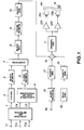
- a digital luminance signal Y and digital color difference signals C R and C B formed from three primary color signals R, G and B, are respectively supplied to input terminals 1Y, 1C R , and 1C B .
- the three primary color signals R, G and B may, for example, be supplied from a color video camera for suitable processing and digitizing in order to provide the input signals as just described.
- the respective clock rates of the input signals are substantially the same as the frequencies of the component signals of the above-mentioned D1 format digital VTR. In other words, the sampling frequencies for the luminance and color difference signals are 13.5 MHz and 6.75 MHz, respectively.
- the number of bits per sample is also 8 bits.
- the amount of data per second which is supplied to the input terminals 1Y, 1C R and 1C B is also approximately 216 Mbps as earlier described.
- the signals from the input terminals 1Y, 1C R and 1C B are supplied to an effective information retrieval circuit 2 which is adapted to omit or remove data from the received signals during the blanking intervals and to retrieve information only from the effective area. As a result, the data are compressed such that the data rate is reduced to approximately 167 Mbps.
- the luminance signal Y from the effective information retrieval circuit 2 is supplied to a frequency conversion circuit 3.
- the frequency conversion circuit 3 converts the sampling frequency from 13.5 MHz into a frequency which is three-fourths of 13.5 MHz.
- the frequency conversion circuit 3 may include a thin-out filter so as to prevent reflected distortion from occurring.
- the output signal of the frequency conversion circuit 3 is supplied to a block segmentation circuit 5.
- the block segmentation circuit 5 converts the received scanning sequence luminance data into a block sequence.
- Fig. 3 is a schematic diagram illustrating a three-dimensional arrangement of blocks which may be used by the block segmentation circuit 5 as an encoding unit. More specifically, by dividing a screen which may occupy, for example, two frames as shown in Fig. 3, a large number of unit blocks (4 lines x 4 picture elements x 2 frames) are formed. In Fig. 3, the solid lines represent lines associated with odd fields, while the broken lines represent lines associated with even fields.
- the two color difference signals C R and C B from the effective information retrieval circuit 2 are supplied to a sub-sampling and sub-line processing circuit 4.
- the sub-sampling and sub-line processing circuit 4 converts the sampling frequency from 6.75 MHz into a frequency which is one-half of 6.75 MHz and then alternatively selects one of the two digital color difference signals for each line. Thereafter, the sub-sampling and sub-line processing circuit 4 composes the two digital color difference signals into one channel of data and outputs a line sequential digital color difference signal.
- Fig. 4 shows picture elements of a signal which have been sub-sampled and sub-lined by the circuit 4.
- "O” represents a sampling picture element of the first color difference signal C R
- " ⁇ ” represents a sampling picture element of the second color difference signal C B
- "X" represents a position in which a picture element has been thinned out by the sampling processing.
- the line sequential signal from the sub-sampling and sub-line processing circuit 4 is supplied to a block segmentation circuit 6.
- the block segmentation circuit 6 converts scanning sequence color difference data into a block sequence data arrangement having a relatively large number of unit blocks, in which each block may be, for example, 4 lines x 4 picture elements x 2 frames.
- the output signals of the block segmentation circuits 5 and 6 are supplied to a composing circuit 7.
- the composing circuit 7 converts the received luminance signal and the color difference signal which have been converted into respective block sequence signals into one channel of data.
- the output signal of the composing circuit 7 is supplied to a block encoding circuit 8.
- Block encoding circuit 8 may, for example, apply adaptive dynamic range coding (ADRC) or may perform a discrete cosine transform in order to compression-code the data blocks supplied thereto.
- ADRC adaptive dynamic range coding
- the block encoding circuit 8 may comprise an encoder similar to that disclosed in Japanese Patent Appln. Nos. SHO 59-266407 and SHO 59-269866, which have a common assignee herewith.
- Such an ADRC encoder generally detects the maximum value and the minimum value of data representing a plurality of picture elements contained in each block and then calculates a dynamic range of the block from the detected maximum and minimum values. Thereafter, the ADRC encoder encodes the data in accordance with the dynamic range such that the data are re-quantized so as to have a lesser number of bits than those of the original picture element data.
- the block encoding circuit may include a discrete cosine transform circuit in which the picture element data of each block are subjected to discrete cosine transform (DCT) processing and the coefficient data obtained by the DCT processing are quantized.
- DCT processing makes use of correlation that is usually present among pixels in a given block so that the coefficient data may be quantized using fewer bits than were used in the original data. Further compression may be achieved by using run-length or Huffman encoding.
- the output signal of block encoding circuit 8 is supplied to a frame segmentation circuit 9.
- the frame segmentation circuit 9 converts the received signal into data in a frame arrangement and converts a picture system data clock into a record system clock.
- the output signal of the frame segmentation circuit 9 is supplied to a parity generation circuit 10 which generates an error correction code parity signal.
- the output signal of the parity generation circuit 10 is supplied to a mixing circuit 15.
- a digital audio signal is supplied from in input terminal 1A to an audio encoding circuit 16.
- the audio encoding circuit 16 may, for example, be adapted to compress the received audio signal by differential pulse code modulation (DPCM) processing.
- DPCM differential pulse code modulation
- the output data of the audio encoding circuit 16 is supplied to a parity generation circuit 17 which generates an error correction code parity signal.
- the parity signal from parity generation circuit 17 is supplied to the mixing circuit 15.
- data generated from a data generation circuit 18 is supplied to parity generation circuit 19.
- the data supplied by data generation circuit 18 includes an identification signal which, as will be discussed below, identifies the track width of signal recording tracks that are produced by the recording section of Fig. 1.
- Data generation circuit 18 may, for example, comprise a microprocessor that controls some or all of the operations of the VTR. It should be noted that data generation circuit 18 may provide data in addition to the track width identification signal.
- Parity generation circuit 19 performs an error correction encoding process on the data received from data generation circuit 18 and generates a parity signal, which is supplied to mixing circuit 15.
- Mixing circuit 15 is adapted to combine the received parity signals from the parity generation circuits 10, 17 and 19 such that picture data, audio data and additional data are arranged in a predetermined pattern.
- the output signal of mixing circuit 15 is supplied to a channel encoder 11 which performs channel encoding so as to decrease the low band of the data to be recorded.
- Channel encoder 11 may include, for example, a scrambling circuit, a so-called class 4 partial response pre-coder, and the like.
- the output signal of the channel encoder 11 is supplied through recording amplifiers 12A and 12B and rotating transformers (not shown) to magnetic heads 13A and 13B, respectively, and is then recorded on magnetic tape 40 by heads 13A and 13B.
- the signal supplied to amplifiers 12A and 12B advantageously also includes automatic track following (ATF) signals to be recorded on the tape 40 to aid in accurate scanning of the signal tracks by magnetic heads during reproducing.
- ATF automatic track following
- signals may comprise, for example, signals of the types disclosed in U.S. Patent No. 5,095,394 and U.S. Appln. Ser. No. 07/699,322 filed May 13, 1991, which have a common assignee herewith.
- Magnetic tape 40 is driven by a motor 14, which, in turn, is controlled by a servo control system (not shown) so that motor 14 runs at a predetermined speed.
- the input data rate of 216 Mbps is reduced to approximately 167 Mbps by retrieving data only from the effective area.
- the frequency conversion and sub-sample and sub-line processing as described above further reduce the data rate to approximately 84 Mbps.
- Compression encoding by block encoder circuit 8 still further reduces the data rate to approximately 25 Mbps. Thereafter, the addition of further data such as parity signals, audio signals and other data increases the data rate to approximately 31.56 Mbps.
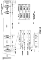
- playback data is obtained from magnetic tape 40 by magnetic heads 13A and 13B and supplied through rotating transformers (not shown) and playback amplifiers 21A and 21B, respectively, to a channel decoder 22.
- ATF signals are provided from amplifiers 21A and 21B to ATF circuitry 34 which provides tracking control signals to a servo control system (not shown) in a manner such as those disclosed in the above referenced U.S. Pat. No. 5,095,394 and Appln. Ser. No. 07/699,322.
- Channel decoder 22 is adapted to reverse the channel encoding performed by channel encoder 11 and may include, for instance, a Viterbi decoder, a de-scrambler, and the like. Practical arrangements of the channel encoder 11 (Fig. 1) and the channel decoder 22 (Fig. 2) may be as disclosed in Japanese Pat. Appln. No. HEI 1-143,491, which has a common assignee herewith.
- the output signal of the channel decoder 22 is supplied to a time base correction (TBC) circuit 23 which removes time base errors from the reproduced signal.
- TBC time base correction
- the reproduced playback from the TBC circuit 23 is supplied to error correction code (ECC) circuits 24, 37 and 49 which correct and modify errors by using a predetermined error correction code. More particularly, the ECC circuit 24 corrects and modifies errors in the picture data, the ECC circuit 37 corrects and modifies errors in the audio data recorded in an audio dedicated area, and the ECC circuit 39 corrects errors in additional data recorded with the picture
- the output signal of the ECC circuit 37 is supplied to an audio decoding circuit 38 which decodes the audio data and outputs a decoded output audio signal to an output terminal 33A.
- the output signal of ECC circuit 24 is supplied to a frame disassembling circuit 25.
- Frame disassembling circuit 25 separates each component of the block encoded picture data and converts the reproducing system clock to a picture system clock.
- Each data component separated in the frame disassembling circuit 25 is supplied to a block decoding circuit 26.
- the block decoding circuit 26 decodes the received data in accordance with the original data of each block and supplies the decoded data to a distribution circuit 27.
- the distribution circuit 27 separates a luminance signal and color difference signal from the received decoded data which are supplied to block disassembling circuits 28 and 29, respectively.
- the block disassembling circuits 28 and 29 function in a substantially opposite manner to that of block segmentation circuits 5 and 6 of Fig. 1. More specifically, the block disassembling circuits 28 and 29 convert the received block sequence signals into raster scanning sequence signals.
- the digital luminance signal Y from the interpolation filter 30 is supplied to an output terminal 33Y.
- the digital color difference signal from the block disassembling circuit 29 is supplied to a distribution circuit 31.
- the distribution circuit 31 separates digital color difference signals C R and C B from the line sequential digital color difference signal.
- the separated digital color difference signals C R and C B are supplied from the distribution circuit 31 to an interpolation circuit 32.
- the interpolation circuit 32 interpolates the received decoded picture element data to obtain the line and picture element data which had been previously thinned out by the circuit 4 of Fig. 1.
- the interpolation circuit 32 supplies digital color difference signals C R and C B , each having a sampling rate of 4 fs, to output terminals 33C R and 33C B , respectively.
- the output signal of ECC circuit 39 is supplied to an I.D. detection circuit 44 which detects a track width identification signal previously recorded and now reproduced from magnetic tape 40.
- the track width identification signal is indicative of the width of oblique tracks that have been formed on the magnetic tape.
- I.D. detection circuit 44 provides to a control circuit 45 a signal that reflects the detected track width identification signal.
- Control circuit 45 controls the running speed of motor 14, and thereby the transport speed of magnetic tape 40, so that the transport speed of magnetic tape 40 can be selected in dependence upon the width of the tracks on magnetic tape 40.
- Control circuit 45 may comprise, for example, a microprocessor that handles servo-control, track following, or other operations of the VTR.
- data in addition to the track width identification signal may be output by ECC circuit 39 to other components (not shown) of the VTR.
- the recording track includes (proceeding sequentially in the head scanning direction from the beginning of the track) a first starting margin area; a track preamble area; an area for recording ATF signals, timing and synchronization signals and additional data; an interblock gap; an audio preamble section; an audio data recording section; and an audio postamble section.
- An interblock gap follows the audio postamble section and is in turn followed by a video preamble section. There next follows the video data recording section; a video postamble section; an interblock gap; a sub-code preamble section; a sub-code data recording section; a sub-code postamble section; and an interblock gap. Following the last mentioned interblock gap is another preamble section and then a second ATF recording section. After the second ATF recording section is a final margin.
- the track width identification signal produced by data generator 18 of Fig. 1, as previously mentioned, may, for example, be recorded in one or more of ID bits or bytes that are part of the first ATF recording section or in the sub-code data recording section.
- a first pair of heads 13A1 and 13B1 and a second pair of heads 13A2 and 13B2 are disposed on a rotary drum 41 so that the respective pairs are diametrically opposed to each other with an angular distance of 180° therebetween.
- a magnetic tape 40 (not shown in Fig. 5) is obliquely wound on the circumferential surface of rotary drum 41 at a winding angle that is, for example, slightly greater than 180° or, alternatively, slightly less than 180°. Accordingly, both heads of a respective pair of heads scan the magnetic tape at the same time for recording or reproduction of data.
- Each pair of heads preferably is formed of a unitary structure and each of the heads of the pair has a mutually different azimuth angle as in the so-called double azimuth head arrangement.
- head 13A has an azimuth angle of, for example, +20° while the polarity of the azimuth angle of head 13B is reversed, i.e., head 13B has an azimuth angle of -20°.
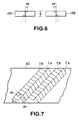
- both of heads 13A and 13B have a width W.
- W is equal to 5 ⁇ m.
- the head width W is twice as large, i.e. 10 ⁇ m.
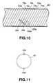
- a recording pattern is formed on the magnetic tape, as shown in Fig. 7, in which adjacent tracks TA and TB on the magnetic tape are formed by the respective magnetic heads 13A and 13B, which have different azimuth angles.
- tracks TA have a direction of magnetization that corresponds to the azimuth angle of magnetic head 13A
- tracks TB have a direction of magnetization that corresponds to the azimuth angle of magnetic head 13B.
- each of the tracks has a track width W which corresponds to the head width W of heads 13A and 13B used to record the tracks. Accordingly, if the head width W is 10 ⁇ m, the track width W of tracks TA and TB also will be 10 ⁇ m. Similarly, if the head width W of heads 13A and 13B is 5 ⁇ m, the track width W of tracks TA and TB also will be 5 ⁇ m.
- Figs. 8A and 8B show a practical arrangement in which magnetic heads 13A1 and 13B1, forming a first pair of magnetic heads, and magnetic heads 13A2 and 13B2 forming a second pair of magnetic heads are provided in respective unified structures making up each pair and thus providing two so-called double azimuth heads arranged in diametrically opposed positions on drum assembly 41.
- drum assembly 41 includes an upper drum 42 on which all of the heads are mounted and which rotates at a high speed of 150 rps for the NTSC system, while a lower drum 43 is fixed.
- Magnetic tape 40 is obliquely wound on drum assembly 41 at a winding angle ⁇ of, for example, 166°.
- Tape 40 is advanced, subject to servo control, in such a manner that, for example, six tracks are scanned by the heads within the time required to record the data for, e.g., one field. Both heads 13A1 and 13B1 or 13A2 and 13B2 of a respective pair of heads simultaneously scan the tape for recording of data or reproducing of data, as the case may be. It is also to be noted that the diameter ⁇ of the above-described drums 42 and 43 is for example, 21 mm.
- the digital VTR is of the type intended to be used in stationary applications and accordingly is provided with magnetic heads 13A1, 13B1, 13A2 and 13B2 (hereinafter simply referred to as magnetic heads 13A, 13B) which have a head width of 5 ⁇ m.
- magnetic heads 13A, 13B which have a head width of 5 ⁇ m.
- tracks TA, TB have a width that is twice as great as the head width of the magnetic heads 13A, 13B.
- the motor 14 of Fig. 2 which was previously referred to, is controlled so that the tape transport speed of magnetic tape 40 is twice as great as the standard tape transport speed used while reproducing signals from a tape recorded by heads 13A and 13B.
- the direction of magnetization of the tracks TA correspond to the azimuth angle of head 13A while the direction of magnetization of the tracks TB correspond to the azimuth angle of head 13B.
- the tracking of heads 13A and 13B is controlled so that head 13A scans the longitudinal half of track TA1 which adjoins track TB1, while head 13B scans the longitudinal half of track TB1 which adjoins track TA1.
- ID detection circuit 44 detects a track width ID signal that had been recorded on magnetic tape 40 and provides an appropriate signal to control circuit 45, which in turn controls motor 14 so that tape 40 is advanced at the required non-standard speed that is twice the standard reproduction transport speed.
- the next scan of a head 13A (shown in phantom and denoted by reference numeral 13A N ) will be of the rightward longitudinal half (i.e., the half adjoining track TB2) of track TA2, while the next scan of a respective head 13B (shown in phantom and denoted by reference numeral 13B N ) will be of the leftward longitudinal half (i.e., the half adjoining track TA2) of track TB2.
- the digital VTR is of the "portable” type and so is provided with magnetic heads 13A, 13B which have a head width of 10 ⁇ m.
- the "portable" VTR is to reproduce a video signal that has been recorded on a magnetic tape by a "stationary" VTR provided with heads that have a head width of 5 ⁇ m, it will be understood that the recorded signal tracks have a track width that is one-half of the head width of the magnetic heads 13A, 13B of the "portable" VTR. Accordingly, as shown in Fig. 10, head 13A simultaneously scans a track TB0 and a track TA1.
- azimuth loss causes the signal reproduced by head 13A from track TB0 to be sufficiently small that it does not significantly interfere with the signal reproduced by head 13A from track TA1.
- head 13B simultaneously scans tracks TB1 and TA2.
- track TA2 has a direction of magnetization that does not correspond to the azimuth angle of head 13B so that the signal reproduced by head 13B from track TA2 is sufficiently small that it does not significantly interfere with the signal reproduced by head 13B from track TB1.
- head 13A is able to reproduce the signals recorded in track TA1 while head 13B is able to reproduce the signals recorded in TB1.
- tape 40 is advanced at a non-standard transport speed that is one-half of the transport speed used for reproduction of signals from wide tracks produced by wide heads 13A and 13B.
- the next scan by a head 13A (shown in phantom and denoted by reference numeral 13A N ) will be of tracks TB1 and TA2 together while the next scan of a head 13B (shown in phantom and denoted by reference numeral 13B N ) will be of tracks TB2 and TA3 together.
- head 13B may be considered a “leading head” and head 13A N a “trailing head” that simultaneously scans adjacent tracks TB1, TA2 after head 13B has done so.
- ID detection circuit 44 (Fig. 2) detects a track width ID signal that was previously recorded on magnetic tape 40 and provides an appropriate signal to control circuit 45, which in turn controls motor 14 so that magnetic tape 40 is transported at the required non-standard (i.e., one-half standard) transport speed.
- provision of the "stationary" and “portable” digital VTRs in accordance with the present invention and respectively having 5 ⁇ m wide and 10 ⁇ m wide magnetic recording heads allows for "bi-directional" compatibility of the magnetic tapes recorded by the respective digital VTRs. That is, tapes recorded using a 5 ⁇ m wide magnetic head can be reproduced by a VTR in accordance with the invention that has a 10 ⁇ m wide magnetic head, while tapes recorded by the latter type of VTR can be reproduced by the former type of VTR which has a 5 ⁇ m wide head.
- a "stationary" VTR of the type described above which has a 5 ⁇ m wide head, is able to reproduce video tapes recorded on a conventional digital VTR having 10 ⁇ m wide heads so that "backward" compatibility with such conventional digital VTRs is achieved. Accordingly, the goal of greater recording density and recording capacity can be achieved using a narrower recording head, without loss of compatibility with VTRs using a wider recording head.
- the present invention is not limited to the above-described embodiment, but also can be applied, for example, to a digital VTR in which only two magnetic heads 13A and 13B are mounted, in diametrically opposed positions, on a rotary drum 41, as shown in Fig. 11. It will be understood that the heads 13A and 13B of Fig. 11 have mutually different azimuth angles.
- the present invention can also be embodied in "reproduce-only” equipment, i.e., in apparatus which has only reproducing, and no recording, electronics.
Landscapes
- Engineering & Computer Science (AREA)
- Signal Processing (AREA)
- Multimedia (AREA)
- Television Signal Processing For Recording (AREA)
- Signal Processing For Digital Recording And Reproducing (AREA)
- Digital Magnetic Recording (AREA)
Applications Claiming Priority (2)
| Application Number | Priority Date | Filing Date | Title |
|---|---|---|---|
| JP3310156A JPH05122647A (ja) | 1991-10-30 | 1991-10-30 | デイジタルビデオテープレコーダ |
| JP310156/91 | 1991-10-30 |
Publications (3)
| Publication Number | Publication Date |
|---|---|
| EP0539922A2 true EP0539922A2 (fr) | 1993-05-05 |
| EP0539922A3 EP0539922A3 (fr) | 1994-03-02 |
| EP0539922B1 EP0539922B1 (fr) | 1999-03-24 |
Family
ID=18001836
Family Applications (1)
| Application Number | Title | Priority Date | Filing Date |
|---|---|---|---|
| EP92118348A Expired - Lifetime EP0539922B1 (fr) | 1991-10-30 | 1992-10-27 | Enregistreur à bande vidéo numérique |
Country Status (4)
| Country | Link |
|---|---|
| US (2) | US5499148A (fr) |
| EP (1) | EP0539922B1 (fr) |
| JP (1) | JPH05122647A (fr) |
| DE (1) | DE69228726T2 (fr) |
Cited By (2)
| Publication number | Priority date | Publication date | Assignee | Title |
|---|---|---|---|---|
| EP0712123A3 (fr) * | 1994-11-14 | 2000-11-29 | Sony Corporation | Enregistrement et reproduction de données |
| EP0831478B1 (fr) * | 1996-09-24 | 2003-11-19 | Hewlett-Packard Company, A Delaware Corporation | Appareil et méthodes de traitement de données |
Families Citing this family (7)
| Publication number | Priority date | Publication date | Assignee | Title |
|---|---|---|---|---|
| US5909638A (en) * | 1996-08-06 | 1999-06-01 | Maximum Video Systems, Inc. | High speed video distribution and manufacturing system |
| JP3293485B2 (ja) * | 1996-08-22 | 2002-06-17 | 松下電器産業株式会社 | ディジタル記録再生装置 |
| JP2001338402A (ja) * | 2000-05-26 | 2001-12-07 | Sony Corp | 磁気記録装置および磁気記録方法 |
| JP2004227704A (ja) * | 2003-01-24 | 2004-08-12 | Sony Corp | ヘッド装置、記録再生装置及び磁気記録方法 |
| US6950039B2 (en) * | 2003-04-10 | 2005-09-27 | Matsushita Electric Industrial Co., Ltd. | Information encoding apparatus, information encoding method, information re-encoding apparatus and information re-encoding method |
| JP4979229B2 (ja) * | 2005-01-13 | 2012-07-18 | インターナショナル・ビジネス・マシーンズ・コーポレーション | 基板に亘って走査するプローブ |
| US9355678B2 (en) | 2014-03-05 | 2016-05-31 | International Business Machines Corporation | Magnetic storage device with multiple read element arrays to determine quality of recorded data |
Citations (5)
| Publication number | Priority date | Publication date | Assignee | Title |
|---|---|---|---|---|
| EP0026320A1 (fr) * | 1979-09-20 | 1981-04-08 | International Business Machines Corporation | Dispositif d'enregistrement et de lecture de données et procédé pour son fonctionnement |
| EP0152242A1 (fr) * | 1984-02-03 | 1985-08-21 | Matsushita Electric Industrial Co., Ltd. | Vidéo enregistreur sur bande |
| US4760474A (en) * | 1985-07-08 | 1988-07-26 | Canon Kabushiki Kaisha | Information signal reproducing apparatus with track pitch discriminating function |
| EP0376675A1 (fr) * | 1988-12-27 | 1990-07-04 | Sharp Kabushiki Kaisha | Dispositif d'enregistrement/reproduction de signaux vidéo |
| US4963991A (en) * | 1988-01-25 | 1990-10-16 | Matsushita Electric Industrial Co., Ltd. | Video tape recorder capable of recording both narrow band and wideband signals |
Family Cites Families (12)
| Publication number | Priority date | Publication date | Assignee | Title |
|---|---|---|---|---|
| JPS5432307A (en) * | 1977-08-17 | 1979-03-09 | Victor Co Of Japan Ltd | Magnetic reproducer |
| JPS56146387A (en) * | 1980-04-15 | 1981-11-13 | Matsushita Electric Ind Co Ltd | Recorder and reproducer of video signal |
| JPS5998307A (ja) * | 1982-11-29 | 1984-06-06 | Hitachi Ltd | 記録および/または再生装置 |
| US4811130A (en) * | 1984-07-02 | 1989-03-07 | Canon Kabushiki Kaisha | Information signal reproducing apparatus capable of determining a track pitch of a record bearing medium using a tracking error signal and a signal indicative of the moving speed of the medium |
| DE3582314D1 (de) * | 1984-12-19 | 1991-05-02 | Sony Corp | Hochleistungsfaehige technik zur kodierung eines digitalen videosignals. |
| JPH0793724B2 (ja) * | 1984-12-21 | 1995-10-09 | ソニー株式会社 | テレビジョン信号の高能率符号化装置及び符号化方法 |
| US5148331A (en) * | 1985-01-25 | 1992-09-15 | Canon Kabushiki Kaisha | Rotary head type recording and reproducing apparatus for information and additional codes |
| US4791497A (en) * | 1985-07-19 | 1988-12-13 | Sony Corp. | Apparatus for recording and/or reproducing, in successive slant tracks on a record tape, at least an audio signal and an index signal for controlling tape transport |
| US4803570A (en) * | 1985-08-06 | 1989-02-07 | Canon Kabushiki Kaisha | Rotary head type multichannel information signal reproducing apparatus having sub-information search function |
| KR910000367B1 (ko) * | 1985-12-18 | 1991-01-24 | 미쓰비시전기 주식회사 | 영상기록 재생장치 |
| JPH038173A (ja) * | 1989-06-06 | 1991-01-16 | Sony Corp | 磁気再生装置 |
| US4963961A (en) * | 1989-06-16 | 1990-10-16 | Burle Technologies, Inc. | Vertical motion detector |
-
1991
- 1991-10-30 JP JP3310156A patent/JPH05122647A/ja not_active Withdrawn
-
1992
- 1992-10-23 US US07/966,540 patent/US5499148A/en not_active Expired - Lifetime
- 1992-10-27 EP EP92118348A patent/EP0539922B1/fr not_active Expired - Lifetime
- 1992-10-27 DE DE69228726T patent/DE69228726T2/de not_active Expired - Fee Related
-
1996
- 1996-03-06 US US08/611,714 patent/US5745318A/en not_active Expired - Fee Related
Patent Citations (5)
| Publication number | Priority date | Publication date | Assignee | Title |
|---|---|---|---|---|
| EP0026320A1 (fr) * | 1979-09-20 | 1981-04-08 | International Business Machines Corporation | Dispositif d'enregistrement et de lecture de données et procédé pour son fonctionnement |
| EP0152242A1 (fr) * | 1984-02-03 | 1985-08-21 | Matsushita Electric Industrial Co., Ltd. | Vidéo enregistreur sur bande |
| US4760474A (en) * | 1985-07-08 | 1988-07-26 | Canon Kabushiki Kaisha | Information signal reproducing apparatus with track pitch discriminating function |
| US4963991A (en) * | 1988-01-25 | 1990-10-16 | Matsushita Electric Industrial Co., Ltd. | Video tape recorder capable of recording both narrow band and wideband signals |
| EP0376675A1 (fr) * | 1988-12-27 | 1990-07-04 | Sharp Kabushiki Kaisha | Dispositif d'enregistrement/reproduction de signaux vidéo |
Cited By (3)
| Publication number | Priority date | Publication date | Assignee | Title |
|---|---|---|---|---|
| EP0712123A3 (fr) * | 1994-11-14 | 2000-11-29 | Sony Corporation | Enregistrement et reproduction de données |
| KR100411167B1 (ko) * | 1994-11-14 | 2004-03-10 | 소니 가부시끼 가이샤 | 영상데이터기록/재생장치및방법 |
| EP0831478B1 (fr) * | 1996-09-24 | 2003-11-19 | Hewlett-Packard Company, A Delaware Corporation | Appareil et méthodes de traitement de données |
Also Published As
| Publication number | Publication date |
|---|---|
| EP0539922B1 (fr) | 1999-03-24 |
| EP0539922A3 (fr) | 1994-03-02 |
| JPH05122647A (ja) | 1993-05-18 |
| DE69228726D1 (de) | 1999-04-29 |
| US5745318A (en) | 1998-04-28 |
| US5499148A (en) | 1996-03-12 |
| DE69228726T2 (de) | 1999-10-14 |
Similar Documents
| Publication | Publication Date | Title |
|---|---|---|
| US5404249A (en) | Digital video tape recorder with data block ID signal error correction | |
| US5416651A (en) | Apparatus for magnetically recording digital data | |
| JP3237152B2 (ja) | ディジタル情報信号の記録装置 | |
| EP0529233B1 (fr) | Enregistreur vidéo numérique avec des modes de reproduction standard et de longue durée | |
| EP0579156A2 (fr) | Procédé d'enregistrement et de reproduction de signal vidéo numérique et dispositif associé | |
| US5377050A (en) | Digital image signal recording-reproducing apparatus and method thereof | |
| EP0483875A2 (fr) | Procédé et appareil pour l'enregistrement magnétique de signaux vidéo numériques et milieu d'enregistrement magnétique à cet effet | |
| EP0620685B1 (fr) | Codage d'un signal vidéo digital | |
| US5499148A (en) | Digital video tape reproducing apparatus compatible with tapes having a track width different from a rotary magnetic head width | |
| EP0483873B1 (fr) | Dispositif pour l'enregistrement magnétique de données numériques | |
| US5526124A (en) | Image recording device, image reproducing device, image recording/reproducing device and image recording method | |
| US6393197B2 (en) | Digital video signal recording/reproducing apparatus and method thereof | |
| EP0523708B1 (fr) | Procédé et dispositif pour l'enregistrement de signaux vidéo numériques | |
| US5864647A (en) | Recording and reproducing apparatus using basic data | |
| US6507695B2 (en) | Digital information signal recording apparatus for recording a digital information signal to a record medium and digital information signal reproducing apparatus for reproducing a digital information signal from a record medium | |
| JP3441004B2 (ja) | 磁気テープおよびデジタル記録再生装置 | |
| JP3232731B2 (ja) | デジタル情報記録再生装置 | |
| JP3259298B2 (ja) | ディジタル画像信号の記録装置 | |
| JP3259324B2 (ja) | ディジタル信号の記録装置および再生装置 | |
| JPH06342565A (ja) | 磁気テープ及びディジタルビデオテープレコーダ | |
| JPH087240A (ja) | 記録/再生装置 | |
| JPH04188980A (ja) | 映像信号の記録再生装置 | |
| JPH07336643A (ja) | デジタル磁気記録及び/又は再生方法とその装置 | |
| JPH05167982A (ja) | デジタルビデオカセットレコーダ | |
| JPH0737209A (ja) | ディジタル信号記録再生装置 |
Legal Events
| Date | Code | Title | Description |
|---|---|---|---|
| PUAI | Public reference made under article 153(3) epc to a published international application that has entered the european phase |
Free format text: ORIGINAL CODE: 0009012 |
|
| AK | Designated contracting states |
Kind code of ref document: A2 Designated state(s): DE FR GB NL |
|
| PUAL | Search report despatched |
Free format text: ORIGINAL CODE: 0009013 |
|
| AK | Designated contracting states |
Kind code of ref document: A3 Designated state(s): DE FR GB NL |
|
| 17P | Request for examination filed |
Effective date: 19940811 |
|
| 17Q | First examination report despatched |
Effective date: 19951127 |
|
| GRAG | Despatch of communication of intention to grant |
Free format text: ORIGINAL CODE: EPIDOS AGRA |
|
| GRAG | Despatch of communication of intention to grant |
Free format text: ORIGINAL CODE: EPIDOS AGRA |
|
| GRAH | Despatch of communication of intention to grant a patent |
Free format text: ORIGINAL CODE: EPIDOS IGRA |
|
| GRAH | Despatch of communication of intention to grant a patent |
Free format text: ORIGINAL CODE: EPIDOS IGRA |
|
| GRAA | (expected) grant |
Free format text: ORIGINAL CODE: 0009210 |
|
| AK | Designated contracting states |
Kind code of ref document: B1 Designated state(s): DE FR GB NL |
|
| REF | Corresponds to: |
Ref document number: 69228726 Country of ref document: DE Date of ref document: 19990429 |
|
| ET | Fr: translation filed | ||
| PLBE | No opposition filed within time limit |
Free format text: ORIGINAL CODE: 0009261 |
|
| STAA | Information on the status of an ep patent application or granted ep patent |
Free format text: STATUS: NO OPPOSITION FILED WITHIN TIME LIMIT |
|
| 26N | No opposition filed | ||
| REG | Reference to a national code |
Ref country code: GB Ref legal event code: IF02 |
|
| PGFP | Annual fee paid to national office [announced via postgrant information from national office to epo] |
Ref country code: NL Payment date: 20081005 Year of fee payment: 17 |
|
| PGFP | Annual fee paid to national office [announced via postgrant information from national office to epo] |
Ref country code: DE Payment date: 20081027 Year of fee payment: 17 |
|
| PGFP | Annual fee paid to national office [announced via postgrant information from national office to epo] |
Ref country code: FR Payment date: 20081014 Year of fee payment: 17 |
|
| PGFP | Annual fee paid to national office [announced via postgrant information from national office to epo] |
Ref country code: GB Payment date: 20081022 Year of fee payment: 17 |
|
| REG | Reference to a national code |
Ref country code: NL Ref legal event code: V1 Effective date: 20100501 |
|
| REG | Reference to a national code |
Ref country code: FR Ref legal event code: ST Effective date: 20100630 |
|
| PG25 | Lapsed in a contracting state [announced via postgrant information from national office to epo] |
Ref country code: DE Free format text: LAPSE BECAUSE OF NON-PAYMENT OF DUE FEES Effective date: 20100501 Ref country code: NL Free format text: LAPSE BECAUSE OF NON-PAYMENT OF DUE FEES Effective date: 20100501 Ref country code: FR Free format text: LAPSE BECAUSE OF NON-PAYMENT OF DUE FEES Effective date: 20091102 |
|
| PG25 | Lapsed in a contracting state [announced via postgrant information from national office to epo] |
Ref country code: GB Free format text: LAPSE BECAUSE OF NON-PAYMENT OF DUE FEES Effective date: 20091027 |