EP0539661A2 - Diesel preheater for engines, particularly for motor vehicle engines - Google Patents
Diesel preheater for engines, particularly for motor vehicle engines Download PDFInfo
- Publication number
- EP0539661A2 EP0539661A2 EP19920112071 EP92112071A EP0539661A2 EP 0539661 A2 EP0539661 A2 EP 0539661A2 EP 19920112071 EP19920112071 EP 19920112071 EP 92112071 A EP92112071 A EP 92112071A EP 0539661 A2 EP0539661 A2 EP 0539661A2
- Authority
- EP
- European Patent Office
- Prior art keywords
- fuel
- heat exchanger
- diesel
- heating
- diesel preheater
- Prior art date
- Legal status (The legal status is an assumption and is not a legal conclusion. Google has not performed a legal analysis and makes no representation as to the accuracy of the status listed.)
- Ceased
Links
- 239000000446 fuel Substances 0.000 claims abstract description 99
- 238000010438 heat treatment Methods 0.000 claims abstract description 91
- 239000000498 cooling water Substances 0.000 claims abstract description 20
- 238000012546 transfer Methods 0.000 claims description 11
- 239000000463 material Substances 0.000 claims description 5
- 230000033228 biological regulation Effects 0.000 claims description 3
- 238000005485 electric heating Methods 0.000 claims description 3
- 239000003302 ferromagnetic material Substances 0.000 claims description 3
- 238000007789 sealing Methods 0.000 claims description 2
- 230000006835 compression Effects 0.000 claims 2
- 238000007906 compression Methods 0.000 claims 2
- 230000001419 dependent effect Effects 0.000 claims 1
- 239000002283 diesel fuel Substances 0.000 abstract description 9
- 238000002485 combustion reaction Methods 0.000 abstract description 3
- 230000005540 biological transmission Effects 0.000 abstract 1
- 230000008878 coupling Effects 0.000 abstract 1
- 238000010168 coupling process Methods 0.000 abstract 1
- 238000005859 coupling reaction Methods 0.000 abstract 1
- 230000007246 mechanism Effects 0.000 abstract 1
- 238000010792 warming Methods 0.000 abstract 1
- XEEYBQQBJWHFJM-UHFFFAOYSA-N Iron Chemical compound [Fe] XEEYBQQBJWHFJM-UHFFFAOYSA-N 0.000 description 4
- 229910052782 aluminium Inorganic materials 0.000 description 4
- XAGFODPZIPBFFR-UHFFFAOYSA-N aluminium Chemical compound [Al] XAGFODPZIPBFFR-UHFFFAOYSA-N 0.000 description 4
- 238000013461 design Methods 0.000 description 4
- 230000000694 effects Effects 0.000 description 3
- 229910052751 metal Inorganic materials 0.000 description 3
- 239000002184 metal Substances 0.000 description 3
- 239000004020 conductor Substances 0.000 description 2
- 238000011161 development Methods 0.000 description 2
- 239000003344 environmental pollutant Substances 0.000 description 2
- 230000002349 favourable effect Effects 0.000 description 2
- 238000002347 injection Methods 0.000 description 2
- 239000007924 injection Substances 0.000 description 2
- 239000011810 insulating material Substances 0.000 description 2
- 229910052742 iron Inorganic materials 0.000 description 2
- 238000004519 manufacturing process Methods 0.000 description 2
- 238000000034 method Methods 0.000 description 2
- 239000010705 motor oil Substances 0.000 description 2
- 238000013021 overheating Methods 0.000 description 2
- 231100000719 pollutant Toxicity 0.000 description 2
- 230000000630 rising effect Effects 0.000 description 2
- 210000002023 somite Anatomy 0.000 description 2
- 238000003860 storage Methods 0.000 description 2
- 239000001993 wax Substances 0.000 description 2
- 238000004804 winding Methods 0.000 description 2
- 239000000956 alloy Substances 0.000 description 1
- 229910045601 alloy Inorganic materials 0.000 description 1
- 239000000919 ceramic Substances 0.000 description 1
- 238000006243 chemical reaction Methods 0.000 description 1
- 238000010276 construction Methods 0.000 description 1
- 239000013078 crystal Substances 0.000 description 1
- 230000005284 excitation Effects 0.000 description 1
- 230000017525 heat dissipation Effects 0.000 description 1
- 238000001746 injection moulding Methods 0.000 description 1
- 239000007788 liquid Substances 0.000 description 1
- 230000007774 longterm Effects 0.000 description 1
- 230000005291 magnetic effect Effects 0.000 description 1
- 239000007769 metal material Substances 0.000 description 1
- 239000012188 paraffin wax Substances 0.000 description 1
- 230000000737 periodic effect Effects 0.000 description 1
- 230000009467 reduction Effects 0.000 description 1
- 230000001105 regulatory effect Effects 0.000 description 1
- 230000000717 retained effect Effects 0.000 description 1
- 239000004065 semiconductor Substances 0.000 description 1
- 238000000926 separation method Methods 0.000 description 1
- 239000007858 starting material Substances 0.000 description 1
- 238000004018 waxing Methods 0.000 description 1
- 238000003466 welding Methods 0.000 description 1
Images


Classifications
-
- F—MECHANICAL ENGINEERING; LIGHTING; HEATING; WEAPONS; BLASTING
- F02—COMBUSTION ENGINES; HOT-GAS OR COMBUSTION-PRODUCT ENGINE PLANTS
- F02M—SUPPLYING COMBUSTION ENGINES IN GENERAL WITH COMBUSTIBLE MIXTURES OR CONSTITUENTS THEREOF
- F02M31/00—Apparatus for thermally treating combustion-air, fuel, or fuel-air mixture
- F02M31/02—Apparatus for thermally treating combustion-air, fuel, or fuel-air mixture for heating
- F02M31/12—Apparatus for thermally treating combustion-air, fuel, or fuel-air mixture for heating electrically
- F02M31/125—Fuel
-
- F—MECHANICAL ENGINEERING; LIGHTING; HEATING; WEAPONS; BLASTING
- F02—COMBUSTION ENGINES; HOT-GAS OR COMBUSTION-PRODUCT ENGINE PLANTS
- F02M—SUPPLYING COMBUSTION ENGINES IN GENERAL WITH COMBUSTIBLE MIXTURES OR CONSTITUENTS THEREOF
- F02M31/00—Apparatus for thermally treating combustion-air, fuel, or fuel-air mixture
- F02M31/02—Apparatus for thermally treating combustion-air, fuel, or fuel-air mixture for heating
- F02M31/16—Other apparatus for heating fuel
-
- F—MECHANICAL ENGINEERING; LIGHTING; HEATING; WEAPONS; BLASTING
- F02—COMBUSTION ENGINES; HOT-GAS OR COMBUSTION-PRODUCT ENGINE PLANTS
- F02B—INTERNAL-COMBUSTION PISTON ENGINES; COMBUSTION ENGINES IN GENERAL
- F02B3/00—Engines characterised by air compression and subsequent fuel addition
- F02B3/06—Engines characterised by air compression and subsequent fuel addition with compression ignition
-
- Y—GENERAL TAGGING OF NEW TECHNOLOGICAL DEVELOPMENTS; GENERAL TAGGING OF CROSS-SECTIONAL TECHNOLOGIES SPANNING OVER SEVERAL SECTIONS OF THE IPC; TECHNICAL SUBJECTS COVERED BY FORMER USPC CROSS-REFERENCE ART COLLECTIONS [XRACs] AND DIGESTS
- Y02—TECHNOLOGIES OR APPLICATIONS FOR MITIGATION OR ADAPTATION AGAINST CLIMATE CHANGE
- Y02T—CLIMATE CHANGE MITIGATION TECHNOLOGIES RELATED TO TRANSPORTATION
- Y02T10/00—Road transport of goods or passengers
- Y02T10/10—Internal combustion engine [ICE] based vehicles
- Y02T10/12—Improving ICE efficiencies
Definitions
- the invention relates to diesel preheaters for engines, in particular vehicle engines according to the preamble of claim 1.
- diesel preheaters were intended to eliminate and prevent the wax from waxing at low temperatures in order to improve the flow behavior, in particular due to the fuel filter, and thereby to prevent the engine from starting and cold-running.
- a diesel preheater should also perform other tasks with higher, more environmentally friendly requirements by helping to shorten the cold runtime, improve engine operation and reduce fuel consumption and pollutant emissions.
- the present invention enables rapid, steeply rising fuel heating up to a certain temperature (of approx. 50-60 o c) is striven for and then kept approximately constant in order to quickly create and maintain favorable, defined conditions for the engine to run.
- the object of the present invention is to meet the requirements set out above for faster and cheaper fuel temperature control in a simple, economical and reliable manner with space-saving and cost-saving preheaters and to avoid known disadvantages.
- This object is achieved according to the invention by features which are contained in the marked parts of several claims. Characterized by the features of claim 1 simple and inexpensive to manufacture components that can be accommodated in a small space perform several functions.
- the fuel heating coil serves and acts simultaneously as an electromagnet and the valve, or rather its piston, as a magnet armature.
- Claim 2 contains further features of the invention with an advantageous further development, in which components also functionally perform multiple tasks and thereby enable considerable cost reductions.
- the advantages of the diesel preheaters described are, on the one hand, their favorable function, which means that the fuel is heated particularly quickly and economically, and, on the other hand, the surprisingly simple, little space demanding structure, which enables material and weight savings as well as cost-effective production.
- the electric fuel heating only works automatically if and as long as it is required at low temperatures, for example during a cold start. Otherwise the fuel temperature is controlled by the heat exchanger, which uses the cooling water temperature, for example.
- Unnecessary, electrical fuel heating is automatically avoided by the rising engine or cooling water temperature immediately contributing to the diesel preheating in order to support the electrical heating and then to switch it off automatically when the heat exchanger alone reaches the desired fuel temperature.
- the rapid increase in temperature that can be achieved with the diesel preheaters described improves the ignitability of the fuel more quickly, which is particularly advantageous during a cold start and during the cold running phase of an engine. With better combustion and shorter cold running times, fuel consumption and pollutant emissions also decrease.
- An effective, fast-acting diesel preheater can even help to reduce friction, wear and engine running noise during cold running.
- the temperature-controlled fuel with a correspondingly more uniform density, creates more defined conditions for more optimal injection, combustion and energy conversion. The following description shows further advantages.
- a (aluminum) tube 2 which is switched on, for example, in the cooling water circuit of a diesel engine and through which cooling water flows, serves as a heat exchanger 6 and has a channel system 4 on its outer circumference for the fuel to be heated.
- the pipe 2 which can also be provided with ribs (not shown) on its inner circumference for better heat transfer, is switched into the cooling water circuit, for example by plugging the cooling water hose ends onto the pipe ends and fastening them with clamps.
- the channel system 4 formed on the circumference of the tube 2 can have any shape and be formed, for example, by ribs 5. It is delimited on both sides by annular disks 3 and sealed, for example, by means of sleeves.
- the duct system 4 is shown schematically and reduced in FIG. 1 for a better overview by a serpentine tube 6 with the feed line 7 and the discharge lines 8 and 9. Above are on one specially designed 3/2-way valve 22, the corresponding line connections 7, 8 and 9 for the channel system 4, which is specifically shown in Fig.1a.
- the changeover or directional control valve 22 is located on a heating chamber 12.
- the fuel feed line is connected to the pipe connection 7, which, as is generally known, comes from the tank via a fuel feed pump; and the opposite pipe connection 10 is connected to the drain line, which supplies the fuel to the injection pump via a filter.
- an electric heating coil 17 in the heating chamber 12 which, for example, can be freely wound in one layer from relatively thick resistance wire.
- the tubular heating coil 17 is connected by an electrically and electromagnetically conductive socket 16, which consists, for example, of ferromagnetic material (iron), to a PTC heating element 15 installed at the output of the heating chamber 12 and connected in series.
- the PTC heating element 15 is contacted, for example, by metal disks or coverings on the front side and on the left side by a metal socket 13 and a contact screw 14 with the housing of the diesel preheater 1 or with the negative or ground line of the (vehicle) Battery 24 connected.
- the right end of the heating coil 17 is electrically insulated by a socket 19 and is connected via a conductive ring contact 18 to the positive pole 26 insulated from the housing.
- the PTC heating element 15 is advantageously with a very low electrical resistance; ie designed for a particularly small electrical voltage and large current, so that the electrical heating power for electrical fuel preheating is mainly applied by the heating coil 17 and less by the PTC element 15.
- PTC element 15 and heating coil 17 are designed and built so that they have intimate contact with the fuel, which can flow around them from all sides.
- the heating coil 17 itself consists of a material or an alloy which has a positive temperature coefficient and can be applied, for example, as a conductor track on a ceramic sleeve.
- the electrical heating chamber 12 is connected through channels shown on the one hand to the central branch 20 of the directional control valve 22 and on the other hand through the socket 13 to the pipe connection 10 of the drain opening.
- the flattening of the adjusting screw 23 shown on one side enables, for example, 2 selectable basic or rest positions of the piston 21 for summer and winter operation.
- a push-button locking element could also be installed for the same task.
- a bimetal or expansion thermostat could be installed in the chamber 12, which is connected to and acts on the piston 21 in order to adjust it continuously or discontinuously to the right as the temperature rises. Both adjustment movements are optionally possible by installing bimetallic disc-type spring washers, which are manufactured with or without a snap effect. As shown, all components 11-22 in the form of a cartridge are accommodated in the sleeve-shaped upper chamber 12 of the diesel preheater 1 between the fuel supply connection 7 and the discharge connection 10.
- the effect of the PTC heating element 15 with its simple, automatic temperature or heating current limitation is retained in spite of the relatively very small design, with the magnetic field of the heating coil 17 for switching or. Tax duties is used.
- the advantageous design and use of individual components for multiple tasks enables uncomplicated, cost-saving construction with increased, increased reliability.
- the compact, slim design enables space to be saved and the shape of the cartridge makes it easy to replace an important component.
- such cartridges can be produced with different heating powers and inserted into one and the same housing of the diesel preheater 1.
- the advantages achieved include the more universal application of the diesel preheater and, at the same time, reduced storage costs.
- FIG. 1a shows a plan view of a section of the duct system 4 that is unwound from the circumference of the tube 2.
- the ribs 5 of the tube 2 are mutually offset to the right and left so that they alternately abut sealing rings or discs 3 on the end face and thus form the serpentine channel system 4, which is interrupted on the directional control valve 22 by a transverse rib 27.
- the left channel next to the transverse rib 27 is connected to the connection 9 of the directional control valve 22, and the connection bores or lines 7 and 8 open into the right channel, as shown in FIG.
- the unproblematic and inexpensive producibility for example from injection molding
- Mode of operation Cold start:
- the electrical heater is connected to the vehicle battery 24 with its connecting terminals 14 and 26 via a symbolically represented switch 25.
- the switch 25 or the heating coil 17 is expediently switched on at the same time as the glow plugs, for example by the preheating starter switch or possibly a preheating control device. Even after the engine has started, the switch 25 is still closed, for example for a limited time or as long as the engine is running.
- the fuel consequently flows from the pipe connection 7 out of the entire channel system 4 of the heat exchanger before it flows through the series-connected electrical heating chamber 12 and the drain opening 10.
- the started engine supports the electrical heating by preheated fuel flowing into the electrical heating chamber 12 as the cooling water temperature rises. As a result, the fuel temperature rises rapidly and the electrical heating phase is shortened.
- the PTC heating element 15 arranged at the output of the heating chamber 12 switches off the electrical heating current, so that the spring 11 pushes the piston 21 back to the right into the rest position shown. In this position, in which the heat exchanger performance is reduced by the branch flow when the valve path 9-20 is slightly open, the piston 21 remains when the engine has reached its operating temperature.
- the fuel temperature at the drain opening 10 is adjusted by means of the screw 23 so that the PTC element 15 can be switched off the electric heater.
- the piston 21 can be set a little more to the left by means of the adjusting screw 23, so that the proportion of the fuel which flows through the entire heat exchanger and the channel 9 increases, and the cooler partial flow through the channel 8 is reduced accordingly.
- the heat exchanger with its duct system 4 is oversized in terms of performance. The switchover, however, avoids overheating of the fuel in the manner described, without the need for a thermostat.
- FIG. 2 shows another cartridge that can be inserted into the electrical heating chamber 12 according to FIG. 1.
- a PTC measuring element 30 for checking the temperature of the preheated fuel is screwed into the drain opening 10. Electrically, it is connected to a switching device 31, to which the heating coil 17 and the (Vehicle) battery 24 is connected to the switch 25.
- One end of the heating coil 17 is connected, for example, in an electrically conductive manner to the housing of the diesel heater 1 and the ground or minus line of the battery 24, while the other end is inserted into the housing of the switching device 31 in an insulated manner.
- the switching device 31 can contain a semiconductor circuit or, in the simplest case, a relay, the excitation winding of which is connected in series with the PTC measuring element 30 and whose switching contact, as shown, is connected to the heating coil 17.
- the relay is automatically activated when the switch 25 is closed and when and as long as the fuel has not reached the desired temperature at the drain opening 10. The rest of the structure and the mode of operation are similar here, as was shown and described in FIG.
- the tubular or cup-like housing 34 which is made, for example, of cast aluminum and serves as a heat exchanger, has ribs 46a and 46b arranged axially on the outer and inner circumference.
- a tubular electrical heating cartridge 17a into which a PTC element in the form of a helical conductor track is integrated, which itself has a positive temperature coefficient.
- the heating cartridge 17a is surrounded by a tube 35, which is open at the bottom and adjoins the inner ribs 46b of the housing 34 all around, so that axially extending channels 45 for the fuel to be preheated are formed therebetween.
- the lower end of the heating cartridge 17a is through an electrically conductive bush 36, which is a bearing 37 for has the piston 21, firmly connected to the housing 34 and thereby to the ground contact 38.
- the heating cartridge 17a is connected to an electrically insulated contact 39 at the top.
- a spring 11 arranged in the bushing 36 presses the piston 21 into its rest position, which can be selected by means of an adjusting screw 40 on the directional control valve 22.
- the diesel preheater 48 has a submersible heat exchanger with continuously adjustable and controllable heat transfer.
- the cup-like housing 49 of the heat exchanger which consists, for example, of cast aluminum, has ribs 50 on the outside and a smooth cylinder bore 51 on the inside the wall of the cylinder bore 51 abuts.
- One end of the coil 52 is fixedly connected to the housing 49 against rotation.
- Within the helix 52 there is, for example, a tube 53 or the tube 35 Heating cartridge at a normally small distance d. With the tube 53, the upper end of the coil 52 is connected in a rotationally secure manner.
- the helix can advantageously be secured to the tube and to the housing in a rotationally secure manner by means of a latching or plug connection by means of a groove and tooth (not shown). It can also consist of conformable, heat-conductive gauze tape (eg metal tape).
- Mode of operation The fuel to be preheated flows in the cylinder bore 51 around the tube 53 (or 35) and through the channel formed by the coil 52 with its turns wound at a distance from one another.
- the fuel is strongly preheated because, on the one hand, the coil 52 normally has close, good metallic contact with the housing 49 and, on the other hand, it has a large surface area for heat dissipation.
- the tube 53 is rotated relative to the housing 49 in such a way that at least some of the helical turns 52 detach from the cylinder wall 51.
- the diesel preheater 48 is therefore very universally adaptable and usable in one and the same size.
- FIG. 5 shows an adjustable and adjustable diesel preheater 55 with a continuous inner tube 56 through which the heat-emitting medium, such as the 100 cooling water, flows. Ribs 57 in it serve for better heat transfer.
- An outer, tubular housing 60 concentrically surrounds the inner tube 56 such that an annular gap 61 is formed between the two.
- the annular gap 61 closed at both pipe ends has an inflow opening 58 and an outflow opening 65 for the fuel.
- the tube 56 which is smooth on the outside, is closely wrapped by a helical coil 62 wound with pretension. This spiral also consists of good heat-insulating material, such as aluminum flat tape. One end thereof is fastened, for example, in a groove 59 on the housing 60 and the other end is free, or adjustable or adjustable.
- teeth 63 are attached to the helix 62, for example, into which a rotatably adjustable gearwheel 64 attached to the housing 60 engages.
- a screw with a screw thread can also be used advantageously.
- the diesel preheater 55 is also very adaptable and can be used more universally.
- An automatic, constant regulation of the fuel temperature is achieved in that, in another embodiment of the diesel preheater 55, the coil 62 is connected to an expansion element 66 attached to the housing 60 and arranged at the drain opening 65.
- This thermostat 66 varies the heat exchange through the loop belt so that the fuel temperature at the drain opening 65 remains almost constant.
- the helix 62 enables the diesel preheater 55 to be constructed inexpensively; it increases the surface area used for heat transfer, forms a suitable channel for the fuel, and is also used here for temperature regulation.
- some turns of the helix 62 can be firmly connected to the tube 56, for example by welding, and only the other turns can be adjustable. A conductive gauze attached between the adjustable turns 62 and the tube 56 can help improve heat transfer (not shown).
- FIG. 6 shows a controllable diesel preheater 68 with a heat exchanger tube 69, which has radial ribs 70 with different diameters. These ribs 70 are arranged along the tube 69 alternately in groups with larger and smaller diameters one behind the other. Above the tube 69 there is a sleeve slide valve 72, which is used to regulate the heat exchanger with the piston 71, 21 or one Thermostat 66 is connected.
- the sleeve valve 72 has incisions 73, o offset by 180, are opposed in pairs in the flow direction and which have in axial direction a distance from one another corresponding to the distance equal to large groups of ribs.
- the tube 69 with the slide 72 is installed in a housing 74, in which a fuel inlet opening 76 and diagonally opposite the outlet opening 75 is seated.
- the Fig.6 shows that in this slide design, the small ribs are constantly used for heat exchange due to their surface.
- the larger fins on the other hand, can be switched on and off depending on the slide position, which means that they more or less contribute to fuel preheating.
- the slide 72 which can be made of heat-insulating or metallic material, is easily adjustable and, despite the small adjustment path s, it can switch many ribs 70 on and off. If the piston 71 is shifted to the left by the adjustment path s, practically all the ribs for heat transfer to the fuel are exposed. In the position shown, however, several large ribs are isolated from the slide 72, ie switched off.
- the number of teeth of the rotary slide valve 83 is expediently smaller than the number of the channels 82, so that when the slide valve rotates, the fuel flow is blocked or at least throttled by a part of the channels 82, while the rest remain open.
- the heat exchanger which is far too large in terms of performance, is initially fully switched on, for example when the engine is cold started and cold running, and after the engine is quickly reached Engine operating temperature set to partial output by rotating the slide. At partial output, the fuel flows through fewer channels at a higher speed, while becoming less warm.
- the rotary valve can be connected to the control piston 71 or to a thermostat 66 (for example made of expansion material or bimetal). Here, too, a small adjustment path is sufficient to limit or regulate the fuel temperature.
- the heat exchanger 80 can advantageously be produced from standard parts by concentrically inserting a finned tube into another tube.
- FIG. 8 shows a diesel preheater with a bypass line 93. It is a sketch of the overall device with a longitudinal section of the preheater housing.
- the diesel fuel preheater has two mass-free electrical connections for supplying electrical energy to the heating coil 97. Furthermore, it has two connections 91 and 92 for the entry and exit of the diesel fuel, the fuel outlet 92 being as close as possible to the entry into the fuel filter.
- the heat exchanger 94 is removed from the cooling water via two further connections (not shown) flows through.
- connection 91 the diesel fuel enters the diesel fuel preheater coming from the tank and leaves it again via connection 92.
- the expansion element 99 uses a push rod 100 to move a slide 101 against the restoring force of a spring 103 when the temperature of the diesel fuel rises at the location of the expansion element 99 to the right in the drawing.
- the spring 103 pushes the slide 101, the push rod 100 and the tappet of the expansion element 99 to the left in the drawing.
- a line 95 is released to a heat exchanger 94, which heats the fuel by means of cooling water heat, or to a bypass line 93.
- the preheater housing 104a, 104b further includes a heating coil 97 for heating the fuel by means of electrical energy.
- the heating coil 97 is connected in series with a thermostat 98.
- the electrical heating current can e.g. be removed from the electrical system of a motor vehicle.
- Heat exchanger 94 and preheater housing 104a, 104b can be structurally connected directly to one another.
Landscapes
- Engineering & Computer Science (AREA)
- Chemical & Material Sciences (AREA)
- Combustion & Propulsion (AREA)
- Mechanical Engineering (AREA)
- General Engineering & Computer Science (AREA)
- Air-Conditioning For Vehicles (AREA)
Abstract
Description
Die Erfindung betrifft Dieselvorwärmer für Motoren, insbes. Fahrzeugmotoren gemäß dem Oberbegriff des Anspruchs 1.The invention relates to diesel preheaters for engines, in particular vehicle engines according to the preamble of claim 1.
Bekannt sind elektrisch beheizte Dieselvorwärmer und solche, die das Kühlwasser, das Motoröl, das Abgas, den Motorblock selbst und ähnliche Wärmequellen zum Erwärmen des Kraftstoffs nutzen.
Nachteilig bei elektrischer Kraftstoff-Erwärmung ist der relativ große, langandauernde Stromverbrauch mit entsprechender Belastung der Batterie und des elektrischen Bordsystems; und nachteilig bei der nichtelektrischen Aufheizung mittels Wärmetauscher ist insbes. die träge Wirkung.
Sie könnte zwar durch Überdimensionierung des Wärmetauschers verbessert werden, bringt dann aber oft den Nachteil mit sich, daß der Kraftstoff u.U. bis zur Dampfblasenbildung überhitzt werden kann.
Ursprünglich und hauptsächlich sollten Dieselvorwärmer die Paraffinierung des Dieselkraftstoffes bei niedrigen Temperaturen beseitigen und verhindern, um das Fließverhalten, insbes. durch das Kraftstoff-Filter, zu verbessern und dadurch Start- und Kaltlaufschwierigkeiten des Motors zu vermeiden. Heute sollte ein Dieselvorwärmer zusätzlich noch weitere Aufgaben mit höheren, umweltschonenderen Anforderungen erfüllen, indem er dazu beiträgt, die Kaltlaufzeit zu verkürzen, den Motorlauf zu verbessern und den Kraftstoffverbrauch wie Schadstoffemissionen zu reduzieren. Zur Erfüllung aller dieser Forderungen wird mit der vorliegenden Erfindung eine schnelle, steil ansteigende Kraftstofferwärmung bis auf eine bestimmte Temperatur (von ca. 50-60oc) angestrebt und diese dann angenähert konstant gehalten, um für den Motorlauf rasch günstige, definierte Bedingungen zu schaffen und beizubehalten. Bekannte Dieselvorwärmer erfüllen die oben gestellten Forderungen nicht, oder sie haben die Nachteile, kompliziert und teuer aufgebaut zu sein, viel Platz zu beanspruchen und wenig Anpassungsfähigkeit zu besitzen. Eine gute Anpassungsfähigkeit soll u.a. angestrebt werden, um mit wenigen Dieselvorwärmer-Größen eine universellere Verwendung für unterschiedliche Motoren zu erreichen.Electrically heated diesel preheaters and those which use the cooling water, the engine oil, the exhaust gas, the engine block itself and similar heat sources for heating the fuel are known.
A disadvantage of electric fuel heating is the relatively large, long-term power consumption with a corresponding load on the battery and the electrical on-board system; and disadvantageous in the case of non-electrical heating by means of a heat exchanger is in particular the sluggish effect.
Although it could be improved by over-dimensioning the heat exchanger, it then often has the disadvantage that the fuel can possibly be overheated until vapor bubbles form.
Originally and primarily, diesel preheaters were intended to eliminate and prevent the wax from waxing at low temperatures in order to improve the flow behavior, in particular due to the fuel filter, and thereby to prevent the engine from starting and cold-running. Today, a diesel preheater should also perform other tasks with higher, more environmentally friendly requirements by helping to shorten the cold runtime, improve engine operation and reduce fuel consumption and pollutant emissions. To meet all of these requirements, the present invention enables rapid, steeply rising fuel heating up to a certain temperature (of approx. 50-60 o c) is striven for and then kept approximately constant in order to quickly create and maintain favorable, defined conditions for the engine to run. Known diesel preheaters do not meet the requirements set out above, or they have the disadvantages of being complex and expensive, taking up a lot of space and having little adaptability. Good adaptability should be aimed at, among other things, in order to achieve more universal use for different engines with just a few diesel preheater sizes.
Aufgabe der vorliegenden Erfindung ist es, die oben aufgestellten Forderungen nach schneller und günstiger KraftstoffTemperierung auf einfache, ökonomische, sowie zuverlässige Weise mit platz- und kostensparenden Vorwärmern zu erfüllen und bekannte Nachteile zu vermeiden. Diese Aufgabe wird erfindungsgemäß durch Merkmale gelöst, die in gekennzeichneten Teilen mehrerer Ansprüche enthalten sind. Durch die gekennzeichneten Merkmale des Anspruchs 1 erfüllen einfache und kostengünstig herstellbare Bauelemente, die auf engem Raum unterbringbar sind, mehrere Funktionen. Hierbei dient und wirkt die Kraftstoff-Heizwendel gleichzeitig als Elektromagnet und das Ventil, oder besser sein Kolben, als Magnetanker. Weitere Merkmale der Erfindung enthält Anspruch 2 mit einer vorteilhaften Weiterbildung, bei der ebenfalls Bauelemente funktionsmäßig mehrfache Aufgaben erfüllen und dadurch erhebliche Kostenreduzierungen ermöglichen. Um eine einfache, günstige Anpassungsfähigkeit der beschriebenen Dieselvorwärmer an unterschiedliche Motoren oder an verschiedene klimatische Bedingungen zu ermöglichen und zusätzliche Vorteile wie Kosteneinsparungen durch Typenreduzierung und geringere Lagerhaltüngskosten zu erreichen, sind Merkmale gemäß einer fortgesetzten Weiterbildung der Erfindung, in den nachfolgenden Ansprüchen gekennzeichnet.The object of the present invention is to meet the requirements set out above for faster and cheaper fuel temperature control in a simple, economical and reliable manner with space-saving and cost-saving preheaters and to avoid known disadvantages. This object is achieved according to the invention by features which are contained in the marked parts of several claims. Characterized by the features of claim 1 simple and inexpensive to manufacture components that can be accommodated in a small space perform several functions. The fuel heating coil serves and acts simultaneously as an electromagnet and the valve, or rather its piston, as a magnet armature.
Die Vorteile der beschriebenen Dieselvorwärmer liegen einerseits in ihrer günstigen Funktion, durch die der Kraftstoff besonders schnell und ökonomisch temperiert wird, und andererseits in dem überraschend einfachen, wenig Platz beanspruchenden Aufbau, der Material- und Gewichtseinsparungen sowie eine kostengünstige Herstellung ermöglicht. Die elektrische Kraftstoffheizung wirkt hilfsweise und automatisch nur, wenn und solange sie bei niedrigen Temperaturen, z.B. bei einem Kaltstart, erforderlich ist. Sonst erfolgt die Kraftstofftemperierung durch den Wärmetauscher, der dazu z.B. die Kühlwassertemperatur nutzt. Eine unnötige, elektrische Kraftstofferwärmung wird selbsttätig vermieden, indem die ansteigende Motor- bzw. Kühlwassertemperatur sofort zur Dieselvorwärmung beiträgt, um zunächst die elektrische Beheizung, zu unterstützen und sie dann automatisch abzuschalten, wenn der Wärmetauscher allein die gewünschte Kraftstofftemperatur erreicht. Durch die mit den beschriebenen Dieselvorwärmern erreichbare rasche Temperaturerhöhung wird die Zündwilligkeit des Kraftstoffs schneller verbessert, was insbes. beim Kaltstart und während der Kaltlaufphase eines Motors vorteilhaft ist. Mit besserer Verbrennung und der Verkürzung der Kaltlaufzeit sinken auch der Kraftstoffverbrauch und die Schadstoffemission. Selbst zur Reduzierung von Reibleistung, Verschleiß und dem während des Kaltlaufes verstärkten Motorlaufgeräusch kann ein effektiver, schnell wirkender Dieselvorwärmer beitragen. Für den betriebswarmen Motor bringt der temperierte Kraftstoff mit entsprechend gleichmäßigerer Dichte definiertere Voraussetzungen für optimalere Einspritzung, Verbrennung und Energieumsetzung. Weitere Vorteile zeigt die folgende Beschreibung auf.The advantages of the diesel preheaters described are, on the one hand, their favorable function, which means that the fuel is heated particularly quickly and economically, and, on the other hand, the surprisingly simple, little space demanding structure, which enables material and weight savings as well as cost-effective production. In the alternative, the electric fuel heating only works automatically if and as long as it is required at low temperatures, for example during a cold start. Otherwise the fuel temperature is controlled by the heat exchanger, which uses the cooling water temperature, for example. Unnecessary, electrical fuel heating is automatically avoided by the rising engine or cooling water temperature immediately contributing to the diesel preheating in order to support the electrical heating and then to switch it off automatically when the heat exchanger alone reaches the desired fuel temperature. The rapid increase in temperature that can be achieved with the diesel preheaters described improves the ignitability of the fuel more quickly, which is particularly advantageous during a cold start and during the cold running phase of an engine. With better combustion and shorter cold running times, fuel consumption and pollutant emissions also decrease. An effective, fast-acting diesel preheater can even help to reduce friction, wear and engine running noise during cold running. For the warm engine, the temperature-controlled fuel, with a correspondingly more uniform density, creates more defined conditions for more optimal injection, combustion and energy conversion. The following description shows further advantages.
Nachstehend wird die Erfindung anhand von in Zeichnungen dargestellten Ausführungsbeispielen näher erläutert.
Es zeigt
- Fig.1
- eine Gesamtansicht eines Dieselvorwärmers mit einem Wärmetauscher und einem Teilschnitt durch seine elektrische Heizungs- und Steuervorrichtung,
- Fig.1a
- ein schlangenförmiges Kanalsystem, das vom Wärmetauscher gemäß Fig.1 abgewickelt und in Umfangsrichtung verkürzt dargestellt ist,
- Fig.2
- einen Schnitt durch eine weitere elektrische Heiz- und Regelvorrichtung z.B. für einen Dieselvorwärmer gemäß Fig.1,
- Fig.3
- einen Schnitt durch einen Dieselvorwärmer mit einem ins wärmeabgebenden Medium eintauchbaren Wärmetauscher und mit einer elektrischen Heizungs- und Steuervorrichtung,
- Fig.4
- einen Dieselvorwärmer mit einem eintauchbaren und regulierbaren Wärmetauscher,
- Fig.5
- einen zur variablen Wärmeübertragung verstell- und regulierbaren Dieselvorwärmer,
- Fig.5a
- einen Teilschnitt A-B am Dieselvorwärmer gemäß Fig.5,
- Fig.6
- einen regulierbaren Dieselvorwärmer mit Hülsenschieber
- Fig.6a
- einen Teilschnitt C-D zu Fig.6,
- Fig.7
- einen regulierbaren Dieselvorwärmer mit Drehschieber,
- Fig.7a
- eine Teilansicht von rechts zu Fig.7,
- Fig.8
- einen regulierbaren Dieselvorwärmer m. Umgehungsleitung.
It shows
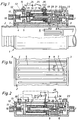
- Fig. 1
- an overall view of a diesel preheater with a heat exchanger and a partial section through its electrical heating and control device,
- Fig.1a
- a serpentine channel system, which is unwound from the heat exchanger according to Figure 1 and shown shortened in the circumferential direction,
- Fig. 2
- 2 shows a section through a further electrical heating and regulating device, for example for a diesel preheater according to FIG. 1,
- Fig. 3
- 2 shows a section through a diesel preheater with a heat exchanger which can be immersed in the heat-emitting medium and with an electrical heating and control device,
- Fig. 4
- a diesel preheater with a submersible and adjustable heat exchanger,
- Fig. 5
- a diesel preheater that is adjustable and adjustable for variable heat transfer,
- Fig.5a
- a partial section AB on the diesel preheater according to Figure 5,
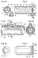
- Fig. 6
- an adjustable diesel preheater with sleeve slide
- Fig.6a
- a partial section CD to Figure 6,
- Fig. 7
- an adjustable diesel preheater with rotary valve,
- Fig.7a
- a partial view from the right to Fig.7,
- Fig. 8
- an adjustable diesel preheater m. Bypass line.
Die Fig.1 zeigt die Gesamtansicht eines Dieselvorwärmers 1, der zum Teil geschnitten dargestellt ist und der z. B. eine birnenförmige Seitenansicht besitzt (ähnlich wie das Gehäuse 74 von Fig.6a). Ein (Alu-) Rohr 2, das beispielsweise in den Kühlwasserkreislauf eines Dieselmotors eingeschaltet ist, und vom Kühlwasser durchströmt wird, dient als Wärmetauscher 6 und besitzt an seinem äußeren Umfang ein Kanalsystem 4 für den zu erwärmenden Kraftstoff. Das Rohr 2, das ebenso an seinem inneren Umfang zur besseren Wärmeübertragung mit Rippen (nicht gezeichnet) versehen sein kann, wird in den Kühlwasserkreislauf eingeschaltet, indem z.B. die Kühlwasser-Schlauchenden auf die Rohrenden aufgesteckt und mittels Schellen befestigt werden. Es kann aber auch ein Rohrende des Wärmetauschers 6 einseitig fest am Motor angeflanscht und dann der Kühlwasserschlauch an anderen, freien Rohrende angeschlossen werden. Das am Umfang des Rohres 2 gebildete Kanalsystem 4 kann beliebig geformt und z.B. durch Rippen 5 gebildet sein. Es ist beiderseitig durch ringförmige Scheiben 3 begrenzt und z.B. mittels Manschetten abgedichtet. Schematisch und verkleinert ist das Kanalsystem 4 in Fig.1 zur besseren Übersicht durch ein schlangenförmiges Rohr 6 mit der Zuleitung 7 und den Ableitungen 8 und 9 dargestellt. Darüber befinden sich an einem besonders ausgebildeten 3/2-Wegeventil 22 die dementsprechenden Leitungsanschlüsse 7, 8 und 9 für das Kanalsystem 4, das in Fig.1a konkret gezeigt ist. Das Umschalt- oder Wegeventil 22 befindet sich an einer Heizkammer 12. An den Rohranschluß 7 wird die Kraftstoff-Zuleitung angeschlossen, die, bekanntlich meistens über eine Kraftstoff-Vorförderpumpe, vom Tank her kommt; und der gegenüberliegende Rohranschluß 10 wird mit der Abflußleitung verbunden, die den Kraftstoff über ein Filter der Einspritzpumpe zuführt. Neben dem Wegeventil 22 befindet sich in der Heizkammer 12 eine elektrische Heizwendel 17, die z.B. einlagig aus relativ dickem Widerstandsdraht frei gewickelt sein kann. Die rohrförmig ausgebildete Heizwendel 17 ist durch eine elektrisch und elektromagnetisch leitfähige Buchse 16, die z.B. aus ferromagnetischem Werkstoff (Eisen) besteht, mit einem am Ausgang der Heizkammer 12 eingebauten PTC-Heizelement 15 verbunden und hintereinandergeschaltet. Das PTC-Heizelement 15 ist z.B. durch Metall-Scheiben oder -Belege stirnseitig kontaktiert und auf der linken Seite durch eine Metall-Buchse 13 und eine Kontaktschraube 14 mit dem Gehäuse des Dieselvorwärmers 1 bzw. mit der Minus- oder Masseleitung der (Fahrzeug-) Batterie 24 verbunden. Das rechte Ende der Heizwendel 17 ist durch eine Buchse 19 elektrisch isoliert und über einen leitfähigen Ringkontakt 18 mit dem vom Gehäuse isolierten Pluspol 26 verbunden. Das PTC-Heizelement 15 ist zweckmäßigerweise mit sehr geringem elektrischem Widerstand; d.h. für eine besonders kleine elektrische Spannung und große Stromstärke ausgelegt, so daß die elektrische Heizleistung zur elektrischen Kraftstoff-Vorwärmung hauptsächlich von der Heizwendel 17 und weniger vom PTC-Element 15 aufgebracht wird. Durch die geringe im PTC-Element 15 umgesetzte elektrische Leistung ist es wesentlich kleiner und kostengünstiger herstellbar, als wenn es, wie üblich, die gesamte elektrische Heizleistung allein aufbringen müßte. PTC-Element 15 und Heizwendel 17 sind so beschaffen und gebaut, daß sie innigen Kontakt mit dem Kraftstoff haben, der sie von allen Seiten her umströmen kann.
In besonders vorteilhafter Weise besteht die Heizwendel 17 selbst aus einem Werkstoff bzw. einer Legierung, die einen positiven Temperaturkoeffizienten besitzt und z.B. als Leiterbahn auf einer Keramikhülse aufgebracht sein kann. Dadurch ist die Selbstregelung in die Heizwendel 17a integriert und das separate PTC-Element 15 überflüssig. Die elektrische Heizkammer 12 ist durch gezeigte Kanäle einerseits mit dem mittleren Zweig 20 des Wegeventils 22 und andererseits durch die Buchse 13 mit dem Rohranschluß 10 der Abflußöffnung verbunden. Ein Kolben 21, der mindestens zum Teil aus ferromagnetischem Werkstoff (z.B. Eisen) besteht, ist innerhalb der Heizwendel 17 und des Wegeventils 22 axial verschiebbar gelagert. Am rechten Ende liegt er an einer Stellschraube 23, an die ihn eine Feder 11 drückt. Mit Hilfe dieser Stellschraube ist die Ruhestellung des Kolbens 21 fein und grob einstellbar bzw. wählbar. Die gezeigte einseitige Abflachung der Stellschraube 23 ermöglicht beispielsweise 2 wählbare Grund- oder Ruhestellungen des Kolbens 21 für Sommer- und Winterbetrieb. An Stelle der Schraube 23 könnte für die gleiche Aufgabe auch eine andere Stellvorrichtung, wie ein Druckknopf-Rastelement, eingebaut sein.
In einer anderen Ausführung könnte an Stelle der Feder 11 z.B. ein Bimetall- oder Dehnstoff-Thermostat in die Kammer 12 eingebaut werden, das mit dem Kolben 21 verbunden ist und auf denselben einwirkt, um ihn mit steigender Temperatur kontinuierlich oder diskontinuierlich nach rechts zu verstellen. Beide Verstellbewegungen sind wahlweise durch den Einbau tellerfederartiger Bimetallscheiben möglich, die ohne oder mit Schnappeffekt hergestellt werden.
Wie dargestellt, sind zwischen dem Kraftstoff-Zuleitungsanschluß 7 und dem Ableitungsanschluß 10 alle Bauteile 11-22 in Form einer Patrone in der hülsenartig ausgebildeten oberen Kammer 12 des Dieselvorwärmers 1 untergebracht. Die Wirkung des PTC-Heizelementes 15 mit seiner einfachen, selbsttätigen Temperatur- bzw. Heizstrom-Begrenzung bleibt hier trotz der relativ sehr kleinen Ausführung erhalten, wobei gleichzeitig das Magnetfeld der Heizwendel 17 für Schaltbzw. Steueraufgaben genutzt wird. Die vorteilhafte Ausführung und Nutzung von einzelnen Bauelementen für mehrfache Aufgaben ermöglicht den unkomplizierten, kostensparenden Aufbau mit gewonnener, gesteigerter Zuverlässigkeit. Die gedrungene, schlanke Bauweise ermöglicht Platzeinsparung und die Patronenform eine leichte Austauschbarkeit einer wichtigen Baugruppe. Insbesondere können solche Patronen mit unterschiedlichen Heizleistungen hergestellt und in ein und dasselbe Gehäuse des Dieselvorwärmers 1 eingesetzt werden. Dadurch erreichte Vorteile sind u.a. die universellere Anwendungsmöglichkeit des Dieselvorwärmers und gleichzeitig reduzierte Lagerhaltungskosten.1 shows the overall view of a diesel preheater 1, which is shown partly in section and which, for. B. has a pear-shaped side view (similar to the
In a particularly advantageous manner, the
In another embodiment, instead of the
As shown, all components 11-22 in the form of a cartridge are accommodated in the sleeve-shaped
Die Fig.1a zeigt eine Draufsicht auf einen vom Umfang des Rohres 2 abgewickelten Abschnitt des Kanalsystems 4.
Die Rippen 5 des Rohres 2 sind wechselseitig nach rechts und links versetzt angeordnet, so daß sie abwechselnd an stirnseitigen Dichtungs-Ringen oder -Scheiben 3 anliegen und damit das schlangenförmige Kanalsystem 4 bilden, das am Wegeventil 22 durch eine Querrippe 27 unterbrochen ist. Der linke Kanal neben der Querrippe 27 ist mit dem Anschluß 9 des Wegeventils 22 verbunden, und in den rechten Kanal münden die Anschlußbohrungen oder Leitungen 7 und 8, wie es darüber die Fig.1 zeigt. Bei dieser Ausführung des Rohres 2 ist die unproblematische und kostengünstige Herstellbarkeit (z.B. aus Spritzguß) vorteilhaft.
Wirkungsweise: Kaltstart: Die elektrische Heizung ist mit ihren Anschlußklemmen 14 und 26 über einen symbolisch dargestellten Schalter 25 an die Fahrzeug-Batterie 24 angeschlossen. Zweckmäßigerweise wird der Schalter 25 bzw. die Heizwendel 17 gleichzeitig mit den Glühkerzen z.B. durch den Vorglühanlaßschalter oder ggfs. ein Vorglühsteuergerät eingeschaltet. Auch nach dem Anspringen des Motors ist der Schalter 25 weiterhin,z.B. zeitlich begrenzt oder solange der Motor läuft, geschlossen. Die von starkem, elektrischen Heizstrom durchflossene Heizwendel 17 zieht den Kolben 21 nach links. Dadurch wild der Kraftstoff-Leitungsweg vom Kanal 8 zum Kanal 20 gesperrt und gleichzeitig der Leitungsweg 9 durch den Kanal 20 zur elektrischen Heizkammer 12 ganz geöffnet. Der Kraftstoff durchströmt demzufolge vom Rohranschluß 7 aus das ganze Kanalsystem 4 des Wärmetauschers, bevor er durch die in Reihe nachgeschaltete elektrische Heizkammer 12 und die Abflußöffnung 10 fließt.
Der gestartete Motor unterstützt die elektrische Heizung, indem mit steigender Kühlwassertemperatur vorgewärmter Kraftstoff in die elektrische Heizkammer 12 strömt. Die Kraftstoff-Temperatur steigt demzufolge rasch an und die elektrische Heizphase wird verkürzt. Wenn die Kraftstofftemperatur auf den gewünschten Wert gestiegen ist, schaltet das am Ausgang der Heizkammer 12 angeordnete PTC-Heizelement 15 den elektrischen Heizstrom ab, so daß die Feder 11 den Kolben 21 nach rechts in die gezeichnete Ruhestellung zurückdrückt. In dieser Stellung, in der die Wärmetauscher-Leistung durch den Zweigstrom bei gering geöffnetem Ventilweg 9-20 reduziert ist, bleibt der Kolben 21, wenn der Motor seine Betriebstemperatur erreicht hat. Dabei ist die Kraftstofftemperatur an der Abflußöffnung 10 mittels der Schraube 23 so eingestellt, daß das PTC-Element 15 die elektrische Heizung abgeschaltet läßt. Bei niedrigen Temperaturen, wie in der Wintersaison, kann der Kolben 21 mittels der Stellschraube 23 etwas mehr nach links gestellt werden, so` daß der Anteil des Kraftstoffes, der durch den ganzen Wärmetauscher und den Kanal 9 fließt, vergrößert, und der kühlere Teilstrom durch den Kanal 8 entsprechend verkleinert wird. Um die gewünschte Kraftstoff-Vorwärmung schnell und stromsparend durchzuführen, ist der Wärmetauscher mit seinem Kanalsystem 4 leistungsmäßig überdimensioniert.
Durch die Umschaltung wird jedoch auf die dargelegte Weise eine Übererwärmung des Kraftstoffs vermieden, ohne dafür einen Thermostaten zu benötigen.1a shows a plan view of a section of the
The
Mode of operation: Cold start: The electrical heater is connected to the
The started engine supports the electrical heating by preheated fuel flowing into the
The switchover, however, avoids overheating of the fuel in the manner described, without the need for a thermostat.
Die Fig.2 zeigt eine andere Patrone, die in die elektrische Heizkammer 12 gemäß Fig.1 eingesetzt werden kann. Hierbei ist an der Abflußöffnung 10 ein PTC-Meßelement 30 zur Kontrolle der Temperatur des vorgewärmten Kraftstoffs eingeschraubt. Elektrisch ist es mit einer Schaltvorrichtung 31 verbunden, an die auch die Heizwendel 17 und die (Fahrzeug-) Batterie 24 mit dem Schalter 25 angeschlossen ist. Ein Ende der Heizwendel 17 ist z.B. elektrisch leitend mit dem Gehäuse des Dieselvowärmers 1 und der Masse- bzw. Minus-Leitung der Batterie 24 verbunden, während das andere Ende isoliert in das Gehäuse der Schaltvorrichtung 31 hineingeführt ist. Die Schaltvorrichtung 31 kann eine Halbleiterschaltung oder im einfachsten Falle ein Relais enthalten, dessen Erregerwicklung mit dem PTC-Meßelement 30 hintereinandergeschaltet ist und dessen Schaltkontakt, wie eingezeichnet, mit der Heizwendel 17 in Verbindung steht. Das Relais wird automatisch aktiviert, wenn der Schalter 25 geschlossen ist und wenn und solange der Kraftstoff die gewünschte Temperatur an der Abflußöffnung 10 nicht erreicht hat. Der übrige Aufbau und die Wirkungsweise sind hier ähnlich, wie es bei der Fig.1 gezeigt und beschrieben wurde.FIG. 2 shows another cartridge that can be inserted into the
Die Fig.3 zeigt einen Dieselvorwärmer 33, der in das wärmeabgebende Medium, das flüssig oder gasförmig sein kann, eintaucht. Dieser Dieselvorwärmer ist z.B. an einer Bohrung am Motorblock 41 angeflanscht, so daß er vom Kühlwasser umspült wird. Er könnte beispielsweise genauso vom Motoröl, von heißer Luft oder vom Abgas aufgeheizt werden. Mindestens z.T. wird er auch durch den Flansch 41 vom Motorblock erwärmt. Das tubenförmige oder becherartige Gehäuse 34, das z.B. aus Alu-Guß besteht und als Wärmetauscher dient, hat am äußeren wie am inneren Umfang axial angeordnete Rippen 46a und 46b. Mitten im Gehäuse 34 befindet sich eine rohrartige elektrische Heizpatrone 17a, in die ein PTC-Element in Form einer wendelförmigen Leiterbahn integriert ist, welche selbst einen positiven Temperaturkoeffizienten besitzt. Die Heizpatrone 17a wird von einem Rohr 35 umgeben, das unten offen ist und rundum an die inneren Rippen 46b des Gehäuses 34 angrenzt, so daß dazwischen axial verlaufende Kanäle 45 für den vorzuwärmenden Kraftstoff gebildet sind. Das untere Ende der Heizpatrone 17a ist durch eine elektrisch leitende Buchse 36, die ein Lager 37 für den Kolben 21 besitzt, fest mit dem Gehäuse 34 und dadurch mit dem Masse-Kontakt 38 verbunden. Oben ist die Heizpatrone 17a an einen elektrisch isolierten Kontakt 39 angeschlossen. Eine in der Buchse 36 angeordnete Feder 11 drückt den Kolben 21 in seine Ruhelage, die mittels einer Stellschraube 40 am Wegeventil 22 wählbar ist.3 shows a
Wirkungsweise: Bei Kaltstart oder unzureichender Kraftstofftemperatur ist die PTC-Heizpatrone 17a eingeschaltet, die den Kolben 21 herabzieht. Der obere Ventilkanal 42-10 wird dadurch geschlossen und der untere, vorher teilweise geöffnete Kanal 43-10 ganz geöffnet. Demzufolge fließt der gesamte Kraftstoff von der Zuleitung 7 durch die Wärmetauscher-Kanäle 45. Danach strömt er in Pfeilrichtung aufwärts durch die elektrische Heizkammer 44 und die untere Ventilöffnung 43 zur Abflußöffnung 10. Sobald der Wärmetauscher die gewünschte Kraftstofftemperierung allein schafft, wird die elektrische Heizung automatisch abgeschaltet und der Kolben 21 mittels der Feder 11 in seine Ruhelage an der Stellschraube 40 zurückgedrückt. Dort bleibt er bei eingetretener Motorbetriebstemperatur, so daß dann nur noch ein Zweigstrom durch den Wärmetauscher fließt. Der zur Schnellen Aufheizung überdimensionierte Wärmetauscher wird dadurch von anfänglicher Maximalleistung auf seine Normalleistung zurückgestellt, bei der keine Übererwärmung des Kraftstoffs am Ausgang 10 eintritt.Mode of operation: In the event of a cold start or insufficient fuel temperature, the
Der Dieselvorwärmer 48 gemäß Fig.4 hat einen eintauchbaren Wärmetauscher mit kontinuierlich einstellbarer und regulierbarer Wärmeübertragung. Das becherartige Gehäuse 49 des Wärmetauschers, das z.B. aus Alu-Guß besteht, hat außen Rippen 50 und innen eine glatte Zylinderbohrung 51. Eine schraubenförmige Wendel 52 aus gut wärmeleitfähigem Material, wie z.B. Alu-Flachband, ist so gewickelt, daß sie mit Vorspannung an der Wandung der Zylinderbohrung 51 anliegt. Ein Ende der Wendel 52, wie beispielsweise das untere, ist mit dem Gehäuse 49 gegen Verdrehung fest verbunden. Innerhalb der Wendel 52 befindet sich z.B. ein Rohr 53 oder das Rohr 35 der Heizpatrone in einem normalerweise kleinen Abstand d. Mit dem Rohr 53 ist das obere Ende der Wendel 52 drehsicher verbunden. Die Wendel kann vorteilhaft am Rohr wie am Gehäuse durch eine Rast- oder Steckverbindung mittels Nut und Zahn drehsicher befestigt sein (nicht gezeichnet). Sie kann auch aus anschmiegsamem, wärmeleitfähigem Gaze-Band (z.B. Metallband) bestehen.
Wirkungsweise: Der vorzuwärmende Kraftstoff strömt in der Zylinderbohrung 51 um das Rohr 53 (oder 35) und durch den Kanal, den die Wendel 52 mit ihren im Abstand voneinander gewickelten Windungen bildet. Der Kraftstoff wird stark vorgewärmt, weil die Wendel 52 einerseits normalerweise engen, gut metallisch leitenden Kontakt mit dem Gehäuse 49 hat und sie andererseits eine große 100 Oberfläche zur Wärmeabgabe besitzt. Wenn in anderen Anwendungsfallen oder zeitweise eine weniger starke Wärmeübertragung erwünscht ist, wird das Rohr 53 relativ zum Gehäuse 49 so verdreht, daß sich mindestens ein Teil der Wendelwindungen 52 von der Zylinderwand 51 löst. Die gelösten Windungen, die sich bis an das innere Rohr 53 anlegen können, übertragen kaum noch Wärme, weil sie durch den Dieselkraftstoff, der eine schlechte Wärmeleitfähigkeit besitzt, vom Gehäuse 49 isoliert sind. Der Dieselvorwärmer 48 ist dadurch in ein- und derselben Größe sehr universell anpaßbar und verwendbar.The
Mode of operation: The fuel to be preheated flows in the cylinder bore 51 around the tube 53 (or 35) and through the channel formed by the
Die Fig.5 zeigt einen verstellbaren und regulierbaren Dieselvorwärmer 55 mit einem durchlaufenden, inneren Rohr 56, durch welches das wärmeabgebende Medium, wie z.B. das 100 Kühlwasser, fließt. Rippen 57 darin dienen zur besseren Wärmeübertragung. Ein äußeres, rohrartig ausgebildetes Gehäuse 60 umgibt das innere Rohr 56 konzentrisch so, daß zwischen beiden ein Ringspalt 61 gebildet wird. Der an beiden Rohrenden geschlossene Ringspalt 61 besitzt eine Zuflußöffnung 58 und eine Abflußöffnung 65 für den Kraftstoff. Das Rohr 56, das außen glatt ist, wird von einer schraubenförmigen und mit Vorspannung gewickelten Wendel 62 eng umschlungen. Auch diese Wendel besteht aus gut wärmeleifähigem Material, wie Alu-Flachband. Ein Ende davon ist z.B. in einer Nut 59 am Gehäuse 60 befestigt und das andere Ende frei, bzw. verstellbar oder regulierbar.
Dazu sind beispielsweise Zähne 63 an der Wendel 62 angebracht, in die ein am Gehäuse 60 befestigtes, drehverstellbares Zahnrad 64 eingreift. Statt dessen kann auch eine Schraube mit Schneckengewinde vorteilhaft verwendet werden. Bei starker, kräftiger Umschlingung des Rohres 56 wird mehr, und bei gelockerten Windungen weniger Wärme auf den Kraftstoff im Ringspalt 61 übertragen. Durch die Verstellbarkeit ist auch der Dieselvorwärmer 55 sehr anpassungsfähig und universeller verwendbar. Eine automatische, stetige Regulierung der Kraftstofftemperatur wird dadurch erreicht, daß in einer anderen Ausführung des Dieselvorwärmers 55 die Wendel 62 mit einem am Gehäuse 60 befestigten und bei der Abflußöffnung 65 angeordneten Dehnstoffelement 66 verbunden ist. Dieses Thermostat 66 variiert den Wärmeaustausch durch das Schlingband so, daß die Kraftstofftemperatur an der Abflußöffnung 65 nahezu konstant bleibt.
Die Wendel 62 ermöglicht einen kostengünstigen Aufbau des Dieselvorwärmers 55; sie vergrößert die zur Wärmeübertragung dienende Oberfläche, bildet einen geeigneten Kanal für den Kraftstoff, und sie dient hier außerdem noch zur Temperaturregulierung. In einer weiteren Ausführung können einige Windungen der Wendel 62 mit dem Rohr 56 z.B. durch Schweißen fest verbunden und nur die übrigen Windungen verstellbar sein. Eine zwischen den verstellbaren Windungen 62 und dem Rohr 56 befestigte, leitfähige Gaze kann zur Verbesserung der Wärmeübertragung beitragen (nicht gezeichnet).5 shows an adjustable and
For this purpose,
The
Die Fig.6 zeigt einen regelbaren Dieselvorwärmer 68 mit einem Wärmetauscher-Rohr 69, das radiale Rippen 70 mit unterschiedlichem Durchmesser besitzt. Diese Rippen 70 sind am Rohr 69 entlang abwechselnd in Gruppen mit größerem und kleinerem Durchmesser hintereinander angeordnet. Über dem Rohr 69 befindet sich ein Hülsenschieber 72, der zur Wärmetauscher-Regulierung mit dem Kolben 71, 21 oder einem Thermostaten 66 verbunden ist. Der Hülsenschieber 72 besitzt Einschnitte 73, die sich, um 180o versetzt, paarweise in Strömungsrichtung gegenüberliegen und die in axialer Richtung einen Abstand voneinander haben, der den Abstand gleichgroßer Rippengruppen entspricht. Das Rohr 69 mit dem Schieber 72 ist in ein Gehäuse 74 eingebaut, in dem eine Kraftstoff-Zuflußöffnung 76 und diagonal gegenüber die Abflußöffnung 75 sitzt. Die Fig.6 zeigt, daß bei dieser Schieber-Ausführung die kleinen Rippen durch ihre Oberfläche ständig zum Wärmeaustausch dienen. Die größeren Rippen sind dagegen, je nach Schieberstellung, wahlweise zu- und abschaltbar, wodurch sie mehr oder weniger zur Kraftstoff-Vorwärmung beitragen. Der Schieber 72, der aus wärmeisolierendem oder auch metallischem Werkstoff bestehen kann, ist leichtgängig verstellbar und er kann trotz kleinem Verstellweg s viele Rippen 70 zu- und abschalten. Wird der Kolben 71 um den Verstellweg s nach links verschoben, so liegen praktisch alle Rippen für die Wärmeübertragung an den Kraftstoff frei. In der gezeichneten Stellung sind dagegen mehrere große Rippen vom Schieber 72 isoliert, d.h. abgeschaltet.6 shows a
Der Dieselvorwärmer 80 in Fig.7, durch dessen Innenrohr z.B. das Kühlwasser strömt, hat zumindest im äußeren Mantel-Bereich axial verlaufende Rippen 81, die die Kanäle 82 für den vorzuwärmenden Kraftstoff bilden. Mindestens an einem Ende der Kanäle 82 ist ein Drehschieber 83 angebracht, der rundum Zähne 84 besitzt, die sich bei ganz eingeschaltetem Wärmetauscher hinter den Rippen 81 befinden. Zweckmäßigerweise ist die Zähnezahl des Drehschiebers 83 kleiner als die Anzahl der Kanäle 82, so daß bei Schieberdrehung der Kraftstofffluß nur durch einen Teil der Kanäle 82 gesperrt oder zumindest gedrosselt wird, während die übrigen andauernd offenbleiben. In Fig.7 steht beispielsweise hinter jeder zweiten Rippe 81 ein Zahn 84 des Drehschiebers 83.
So ist der leistungsmäßig weit überdimensionierte Wärmetauscher z.B. beim Kaltstart und Kaltlauf des Motors zunächst ganz eingeschaltet und nach schnellem Erreichen der Motor-Betriebstemperatur durch Schieberdrehung auf Teilleistung gestellt. Bei Teilleistung strömt der Kraftstoff durch weniger Kanäle mit gleichzeitig höherer Geschwindigkeit, wobei er weniger warm wird. Der Drehschieber kann mit dem Steuer-Kolben 71 oder mit einem Thermostat 66 (z.B. aus Dehnstoff oder Bimetall) verbunden sein. Auch hierbei genügt ein kleiner Verstellweg zur Begrenzung oder Regulierung der Kraftstofftemperatur. Der Wärmetauscher 80 kann vorteilhaft aus Normteilen hergestellt werden, indem ein Rippenrohr konzentrisch in ein weiteres Rohr gesteckt wird.The
The heat exchanger, which is far too large in terms of performance, is initially fully switched on, for example when the engine is cold started and cold running, and after the engine is quickly reached Engine operating temperature set to partial output by rotating the slide. At partial output, the fuel flows through fewer channels at a higher speed, while becoming less warm. The rotary valve can be connected to the
In der Figur 8 wird ein Dieselvorwärmer mit einer Umgehungsleitung 93 dargestellt. Es ist eine Skizze der Gesamtvorrichtung mit einem Längsschnitt des Vorwärmergehäuses.FIG. 8 shows a diesel preheater with a
Der Dieselkraftstoffvorwärmer besitzt zwei massefreie elektrische Anschlüsse für die Zuführung elektrischer Energie zur Heizwendel 97. Weiterhin weist er zwei Anschlüsse 91und 92 für den Ein- und Austritt des Dieselkraftstoffs auf, wobei der Kraftstoffaustritt 92 möglichst nahe beim Eintritt in den Kraftstoffilter liegen sollte. Über zwei weitere (nicht dargestellte) Anschlüsse wird der Wärmetauscher 94 vom Kühlwasser durchströmt.The diesel fuel preheater has two mass-free electrical connections for supplying electrical energy to the
Über den Anschluß 91 tritt der Dieselkraftstoff aus dem Tank kommend in den Dieselkraftstoffvorwärmer ein und verläßt ihn wieder über den Anschluß 92. Im Innern des Vorwärmergehäuses 104a,104b, das auch einteilig sein kann, befindet sich ein Dehnstoffelement 99, welches durch eine Feder 102 kraftschlüssig mit dem Gehäuseteil 104a verspannt ist. Das Dehnstoffelement 99 verschiebt mittels einer Druckstange 100 einen Schieber 101 gegen die Rückstellkraft einer Feder 103 bei steigender Temperatur des Dieselkraftstoffs am Ort des Dehnstoffelements 99 in der Zeichnung nach rechts. Bei sinkender Temperatur des Kraftstoffs drückt die Feder 103 den Schieber 101, die Druckstange 100 und den Stößel des Dehnstoffelementes 99 in der Zeichnung nach links. Je nach Stellung des Schiebers 101 wird eine Leitung 95 zu einem Wärmetauscher 94, der den Kraftstoff mittels Kühlwasserwärme aufheizt, oder zu einer Umgehungsleitung 93 freigegeben. Weiterhin beinhaltet das Vorwärmergehäuse 104a,104b eine Heizwendel 97 zum Aufheizen des Kraftstoffs mittels elektrischer Energie. Die Heizwendel 97 ist in Reihe mit einem Thermostaten 98 geschaltet. Der elektrische Heizstrom kann z.B. dem Bordnetz eines Kraftfahrzeuges entnommen werden.Via
Der Kraftstoffstrom, der durch den Anschluß 91 eintritt, wird im Schieber 101 in zwei Teilströme aufgeteilt. Dabei strömt ein Teilstrom durch die Umgehungsleitung 93 und der andere durch die Leitung 95 zum Wärmetauscher 94 und von dort zurück zu einer Kammer 106, in der sich die Heizwendel 97 befindet, über eine Leitung 96. Dabei sind folgende Betriebszustände zu unterscheiden:
- a.
Der Kraftstoff hat im Zulauf bereits eine Temperatur oberhalb der kritischen Paraffin-Ausscheidungstemperatur. Ein Aufheizen des Dieselkraftstoffs wird deswegen nicht benötigt.Das Dehnstoffelement 99 drückt aufgrund der hohen Kraftstofftemperatur den Schieber 101 nach rechts, wodurchKanal 95 weitgehend geschlossen undKanal 93, die Umgehungsleitung, geöffnet wird.Die Leitung 95 wird deshalb nicht ganz geschlossen, damit der in ihr befindliche Dieselkraftstoff nicht altert oder verharzt. So wird überden Wärmetauscher 94 nur verschwindend wenig Kühlwasserwärme zugeführt. Außerdem befindet sich der durchden Thermostaten 98betätigte Schalter 105 im Offenzustand, so daß kein Heizstrom fließt. Es fließt somit fast die gesamte Kraftstoffmenge über dieUmgehungsleitung 93zum Dehnstoffelement 99 und von dort überden Kraftstoffaustritt 92 zum Kraftstoffilter. - b.
Die Kraftstofftemperatur liegt unterhalb der kritischen Temperatur, bei der Paraffinkristalle ausfallen können.Das Dehnstoffelement 99 erkennt die niedrige Temperatur und läßt den Schieber 101 durch dieFeder 103 nach links (in der Zeichnung) drücken. Dadurch wird dieUmgehungsleitung 93 verschlossen und dieLeitung 95 geöffnet. Der Kraftstoff fließt überden Wärmetauscher 94, wo er sich je nach Kühlwassertemperatur mehr oder weniger stark aufheizt. Ist das Kühlwasser noch kalt, strömt der kalte Kraftstoff indie Kammer 106zur Heizwendel 97 und zum Thermostaten 98, der daraufhinden Schalter 105 betätigt, so daß Strom zur Heizwendel fließt. Die Kraftstofftemperatur inder Kammer 106der Heizwendel 97 übersteigt dabei die gewünschte Kraftstofftemperatur am Ausgang zum Kraftstoffilter.Das Dehnstoffelement 99 heizt sich auf und drückt mittels derDruckstange 100 den Schieber 101 etwas nach rechts (in der Zeichnung), so daß dieUmgehungsleitung 93 teilweise geöffnet wird und innerhalb gewisser Toleranzen die Sollausgangstemperatur erreicht wird. - c.
Heizt sich aufgrund sehr geringen Kraftstoffdurchsatzes der Kraftstoff inder Kammer 106der Heizwendel 97 zu stark auf, dann öffnet oberhalb einer vorzugebenden Temperaturschwelle derThermostat 98den Schalter 105 und unterbricht damit den Stromkreis, wodurch sich wieder ein Temperaturabfall und somit ein sich periodisch wiederholender Regelvorgang ergibt. Heizt sich in der Zwischenzeit das Kühlwasser auf, dann trifft derim Wärmetauscher 94 vorgewärmte Kraftstoff auf dieHeizwendel 97. Die Kraftstofftemperatur inder Kammer 106der Heizwendel 97 steigt dadurch relativ schneller an und erreicht dementsprechend eher die Temperatur, bei der derThermostat 98den Schalter 105 öffnet und damit denStrom zur Heizwendel 97 unterbricht. Dieser periodische Regelvorgang wiederholt sich in gleicher Weise, wie oben beschrieben, so lange, bisder den Wärmetauscher 94 verlassende Kraftstoff eine so hohe Temperatur aufweist, daß derSchalter 105 dauernd geöffnet bleibt. Bei zu hoher Aufheizung desKraftstoffs im Wärmetauscher 94schiebt das Dehnstoffelement 99mit der Druckstange 100 den Schieber 102 (in der Zeichnung) nach rechts, wodurch nicht vorgewärmter Kraftstoff durch dieUmgehungsleitung 93 in einer gewissenMenge zum Dehstoffelement 99 fließt und sich mit demaus dem Wärmetauscher 94 kommenden vorgewärmten Kraftstoffstrom mischt. Hierdurch wird innerhalb gewisser Toleranzen die Sollausgangstemperatur des Kraftstoffs sichergestellt.
- a.
The fuel already has a temperature above the critical paraffin separation temperature. It is therefore not necessary to heat the diesel fuel. Theexpansion element 99 presses due to the high fuel temperature slide 101 to the right, which largely closeschannel 95 and openschannel 93, the bypass line. Theline 95 is therefore not completely closed so that the diesel fuel in it does not age or become resinous. Only a negligible amount of cooling water heat is supplied via theheat exchanger 94. In addition, theswitch 105 operated by thethermostat 98 is in the open state, so that no heating current flows. Almost the entire amount of fuel thus flows via thebypass line 93 to theexpansion element 99 and from there via thefuel outlet 92 to the fuel filter. - b.
The fuel temperature is below the critical temperature at which wax crystals can fail. Theexpansion element 99 detects the low temperature and has the slide 101 pressed by thespring 103 to the left (in the drawing). This closes thebypass line 93 and opens theline 95. The fuel flows through theheat exchanger 94, where it heats up to a greater or lesser extent depending on the cooling water temperature. If the cooling water is still cold, the cold fuel flows into thechamber 106 to theheating coil 97 and to thethermostat 98, which then actuates theswitch 105 so that current flows to the heating coil. The fuel temperature inchamber 106 ofheating coil 97 exceeds the desired fuel temperature at the outlet to the fuel filter. Theexpansion element 99 heats up and pushes the slide 101 a little to the right (in the drawing) by means of thepush rod 100, so that thebypass line 93 is partially opened and the target outlet temperature is reached within certain tolerances. - c.
If the fuel in thechamber 106 of theheating coil 97 heats up too much due to the very low fuel throughput, then it opens above a predefinedtemperature threshold Thermostat 98switches 105 and thus interrupts the circuit, which again results in a temperature drop and thus a periodically repeating control process. If the cooling water heats up in the meantime, the fuel preheated in theheat exchanger 94 hits theheating coil 97. As a result, the fuel temperature in thechamber 106 of theheating coil 97 rises relatively faster and, accordingly, reaches the temperature at which thethermostat 98switches 105 opens and thus interrupts the current to theheating coil 97. This periodic control process is repeated in the same way as described above until the fuel leaving theheat exchanger 94 has such a high temperature that theswitch 105 remains open continuously. If the fuel in theheat exchanger 94 heats up too much, theexpansion element 99 with thepush rod 100 pushes the slide 102 (in the drawing) to the right, as a result of which non-preheated fuel flows through thebypass line 93 in a certain amount to theexpansion element 99 and flows out of itHeat exchanger 94 mixes incoming preheated fuel flow. This ensures the target output temperature of the fuel within certain tolerances.
Wärmetauscher 94 und Vorwärmergehäuse 104a,104b können baulich direkt miteinander verbunden sein.
Claims (18)
dadurch gekennzeichnet,
daß sowohl die elektrische Heizkammer (12) als auch der Wärmetauscher (6; 34) an ein 3/2-Wegeventil (22) angeschlossen sind, wobei bei aktiviertem Ventil (22) der gesamte Kraftstoff den Wärmetauscher (6; 34) und die ihm nachgeschaltete Heizkammer (12) durchfließt und bei inaktivem Ventil (22) nur ein Zweigstrom des Kraftstroms durch den Wärmetauscher (6; 34) geleitet wird,
daß das Heizelement als Heizwendel (17) ausgebildet ist und daß zur temperaturabhängigen Regelung ein verstellbarer Kolben (21), der mindestens zum Teil aus ferromagnetischem Werkstoff besteht, innerhalb der Heizwendel (17) und des Ventils (22) verschiebbar angeordnet ist.Diesel preheater for engines, especially vehicle engines, where the fuel can be heated both electrically and by means of a heat exchanger, with a separate electrical heating chamber that can be attached to the heat exchanger and has an electrically charged heating element made of a material with a positive temperature coefficient that can be switched on and off by a switching device can be switched off,
characterized,
that both the electric heating chamber (12) and the heat exchanger (6; 34) are connected to a 3/2-way valve (22), wherein when the valve (22) is activated, the entire fuel, the heat exchanger (6; 34) and it flows through the downstream heating chamber (12) and when the valve (22) is inactive, only a branch flow of the power flow is passed through the heat exchanger (6; 34),
that the heating element is designed as a heating coil (17) and that an adjustable piston (21), which consists at least partly of ferromagnetic material, is arranged displaceably within the heating coil (17) and the valve (22) for temperature-dependent control.
dadurch gekennzeichnet,
daß ein PTC-Heizelement (15) am Ausgang der Heizkammer (12) und unmittelbar an die Heizwendel (17) angrenzend angeordnet ist, mit der es hintereinandergeschaltet ist.Diesel preheater according to claim 1,
characterized,
that a PTC heating element (15) at the output of the heating chamber (12) and directly adjacent to the heating coil (17) is arranged, with which it is connected in series.
dadurch gekennzeichnet,
daß das PTC-Meßelement (30) am Ausgang der Heizkammer (12) mit Abstand von der Heizwendel (17) angeordnet ist.Diesel preheater according to claim 1,
characterized,
that the PTC measuring element (30) is arranged at the outlet of the heating chamber (12) at a distance from the heating coil (17).
dadurch gekennzeichnet,
daß eine Stellvorrichtung (23; 40) für den Kolben (21) zur Veränderung seiner Ruhelage vorgesehen ist.Diesel preheater according to claim 1,
characterized,
that an adjusting device (23; 40) for the piston (21) is provided for changing its rest position.
dadurch gekennzeichnet,
daß zum Verstellen des Kolbens (21) in der Heizkammer (12) ein Thermostat vorgesehen ist.Diesel preheater according to claim 1,
characterized,
that a thermostat is provided for adjusting the piston (21) in the heating chamber (12).
dadurch gekennzeichnet,
daß auf seiner äußeren Mantelfläche abwechselnd nach rechts und links versetzte Rippen (5) mit stirnseitigen Dichtungs-Scheiben (3) das mäandierende Kanalsystem (4) bilden, daß ein Quersteg (27) den Kanal (4) schließt und daß rechts und links vom Steg (27) Anschlußbohrungen (7,8,9)vom Wegeventil (22) in den Kanal (4) einmünden.Diesel preheater according to claim 1 with a heat exchanger made of a tubular body, the cooling water flows around the inside and the fuel meanders around the outside,
characterized,
that on its outer circumferential surface alternately offset to the right and left ribs (5) with front sealing washers (3) form the meandering channel system (4), that a crossbar (27) closes the channel (4) and that right and left of the web (27) Open the connection bores (7,8,9) from the directional control valve (22) into the channel (4).
dadurch gekennzeichnet,
daß das Gehäuse (34) mit äußeren und inneren axial gerichteten Rippen (46a, 46b) in der Mitte eine austauschbare Patrone aus einem einseitig offenen Rohr (35) aufweist, das mit den inneren Rippen (46b) Kanäle (45) bildet und in das die elektrische Heizkammer (44) eingebaut ist, welche auf der anderen Seite mit dem Wegeventil (22) in Verbindung steht.Diesel preheater according to claim 1 with a heat exchanger from a cup-like housing, which is immersed in a heat-emitting medium,
characterized,
that the housing (34) with outer and inner axially directed ribs (46a, 46b) in the middle has a replaceable cartridge made of a tube (35) which is open on one side and which forms channels (45) with the inner ribs (46b) and into which the electric heating chamber (44) is installed, which is connected to the directional control valve (22) on the other side.
dadurch gekennzeichnet,
daß die Rippen (70) am Rohr (69) entlang abwechselnd in Gruppen mit größerem und kleinerem Durchmesser hintereinander angeordnet sind, daß sich über dem Rohr (69) ein Hülsenschieber (72) mit Einschnitten (73) befindet, die einander paarweise gegenüberliegen, um Rippen (70) wahlweise freizulegen, und daß der Hülsenschieber (72) zur Wärmeregulierung mit einer Einstellvorrichtung (71; 21; 66) in Verbindung steht.Diesel preheater according to claim 1 with a heat exchanger having a tube with radial ribs between the heat-emitting medium and the fuel,
characterized,
that the ribs (70) along the tube (69) are arranged alternately in groups with larger and smaller diameters one behind the other, that over the tube (69) there is a sleeve slide valve (72) with incisions (73) which are opposite one another in pairs Optionally expose the ribs (70) and that the sleeve slide (72) is connected to an adjusting device (71; 21; 66) for heat regulation.
dadurch gekennzeichnet,
daß die Rippen (81) Kanäle (82) bilden, daß mindestens an einem Ende der Kanäle (82) ein Drehschieber (83) angebracht und mit einer Einstellvorrichtung (71; 66) verbunden ist, um den Kraftstoffdurchfluß durch mehrere der Kanäle (82) zu regeln, wahlweise abzusperren oder mindestens zu behindern.Diesel preheater according to claim 1 with a heat exchanger having a tube with axial fins between the heat-emitting medium and the fuel,
characterized,
that the ribs (81) form channels (82), that at least at one end of the channels (82) a rotary slide valve (83) is attached and connected to an adjusting device (71; 66) to limit the fuel flow through several of the channels (82) to regulate, either to shut off or at least to hinder.
dadurch gekennzeichnet,
daß eine Wendel (52; 62) aus wärmeleitfähigem, spannbarem Band im Ringspalt (61) angeordnet ist, die einen Kanal für den Kraftstoff bildet, und daß die Wendel (52; 62) mindestens teilweise mittels einer Stellvorrichtung (64; 66) von einem der beiden Rohre (56, 49) lösbar ist, um den Wärmeübergang an den Kraftstoff zu verändern.Diesel preheater, in particular according to claim 1, having a heat exchanger which has an inner and an outer tube which are arranged concentrically to one another and which form an annular gap for one medium, while the other medium is connected to the inner tube,
characterized,
that a coil (52; 62) made of thermally conductive, tensionable tape is arranged in the annular gap (61), which forms a channel for the fuel, and that the coil (52; 62) at least partially by means of an adjusting device (64; 66) by one of the two pipes (56, 49) is detachable in order to change the heat transfer to the fuel.
dadurch gekennzeichnet,
daß die Wendel (52; 62) mindestens zum Teil aus gazeartigem Band besteht.Diesel preheater according to claim 10,
characterized,
that the coil (52; 62) consists at least in part of gauze-like tape.
dadurch gekennzeichnet,
daß das eine Ende der Wendel (52; 62) am inneren Rohr (56) und das andere Ende am Gehäuse (49) befestigt ist, wobei Rohr (56) und Gehäuse (49) relativ zueinander einstellbar sind, um den Wärmeübergang zwischen beiden Medien den Erfordernissen anzupassen.Diesel preheater according to claim 10 or 11,
characterized,
that one end of the coil (52; 62) is fastened to the inner tube (56) and the other end to the housing (49), the tube (56) and housing (49) being adjustable relative to one another in order to increase the heat transfer between the two media adapt to the requirements.
dadurch gekennzeichnet,
daß die Stellvorrichtung (64) einen Dehnstoff-Thermostaten (66) umfaßt, der mit der Wendel (62) verbunden ist.Diesel preheater according to claim 10 or 11,
characterized,
that the actuating device (64) comprises an expansion thermostat (66) which is connected to the coil (62).
dadurch gekennzeichnet,
daß in einem Gehäuseteil (104b) des Dieselvorwärmers ein Schieber (101) axial verschiebbar angeordnet ist, der einen Kraftstoffeinlaß (91) und zwei Kraftstoffauslässe (Umgehungsleitung 93, Leitung 95) aufweist,
daß ein Dehnstoffelement (99) zum Betätigen des Schiebers (101) in Abhängigkeit von der Kraftstoff-Austrittstemperatur vorgesehen ist,
daß das Heizelement als Heizwendel (97) ausgebildet ist, die über einen Thermostaten (98) mit zugeordnetem Schalter (105) mit Strom zum Aufheizen in Abhängigkeit von der Temperatur des den Wärmetauscher (94) verlassenden Kraftstoffs beaufschlagt wird, und
daß zwischen dem Schieber (101) und einem Raum (108) zur Aufnahme des Dehnstoffelements (99) eine die Heizwendel (97) und den Wärmetauscher (94) umgehende Umgehungsleitung (93) vorgesehen ist.Diesel preheater for engines, especially vehicle engines, where the fuel can be heated both electrically and by means of a heat exchanger, with a separate electrical heating chamber that can be attached to the heat exchanger and has an electrically charged heating element made of a material with a positive temperature coefficient that can be switched on and off by a switching device can be switched off,
characterized,
that a slide (101) is arranged axially displaceably in a housing part (104b) of the diesel preheater and has a fuel inlet (91) and two fuel outlets (bypass line 93, line 95),
that an expansion element (99) is provided for actuating the slide (101) as a function of the fuel outlet temperature,
that the heating element is designed as a heating coil (97), which is supplied with current for heating as a function of the temperature of the fuel leaving the heat exchanger (94) via a thermostat (98) with an associated switch (105), and
that a bypass line (93) bypassing the heating coil (97) and the heat exchanger (94) is provided between the slide (101) and a space (108) for receiving the expansion element (99).
dadurch gekennzeichnet,
daß zwischen Dehnstoffelement (99) und Schieber (101) eine Druckstange (100) zum differenzierten Öffnen und Schließen der Schieberauslässe (95,96) in Abhängigkeit von der Kraftstofftemperatur am Dieselvorwärmer-Austritt (92) vorgesehen ist.Diesel preheater according to claim 14,
characterized,
that between the expansion element (99) and slide (101) a push rod (100) is provided for differentiated opening and closing of the slide outlets (95,96) depending on the fuel temperature at the diesel preheater outlet (92).
dadurch gekennzeichnet,
daß zwischen einen Raum (106) zum Aufheizen des Kraftstoffs durch die Heizwendel (97) und dem Raum (108) zur Aufnahme des Dehnstoffelements (99) eine Kraftstoff-Verbindungsleitung (197) vorgesehen ist.Diesel preheater according to claim 14 or 15,
characterized,
that between a space (106) for heating the fuel a fuel connection line (197) is provided through the heating coil (97) and the space (108) for receiving the expansion element (99).
dadurch gekennzeichnet,
daß zum kraftschlüssigen Verspannen des Dehnstoffelements (99) mit dem einen Gehäuseteil (104a) eine Druckfeder (102) vorgesehen ist.Diesel preheater according to one of claims 14 to 16,
characterized,
that a compression spring (102) is provided for the non-positive clamping of the expansion element (99) with the one housing part (104a).
dadurch
daß zum kraftschlüssigen Verspannen des Schiebers (101) mit dem anderen Gehäuseteil (104b) eine Druckfeder (103) vorgesehen ist.Diesel preheater according to one of claims 14 to 17,
thereby
that a compression spring (103) is provided for the positive locking of the slide (101) with the other housing part (104b).
Applications Claiming Priority (4)
| Application Number | Priority Date | Filing Date | Title |
|---|---|---|---|
| DE4123866A DE4123866C2 (en) | 1991-07-18 | 1991-07-18 | Diesel preheaters for engines, in particular vehicle engines |
| DE4123866 | 1991-07-18 | ||
| DE4223030A DE4223030A1 (en) | 1992-07-15 | 1992-07-15 | Diesel fuel pre-warming device, esp. for vehicle engine |
| DE4223030 | 1992-07-15 |
Publications (2)
| Publication Number | Publication Date |
|---|---|
| EP0539661A2 true EP0539661A2 (en) | 1993-05-05 |
| EP0539661A3 EP0539661A3 (en) | 1993-08-11 |
Family
ID=25905612
Family Applications (1)
| Application Number | Title | Priority Date | Filing Date |
|---|---|---|---|
| EP19920112071 Ceased EP0539661A3 (en) | 1991-07-18 | 1992-07-15 | Diesel preheater for engines, particularly for motor vehicle engines |
Country Status (1)
| Country | Link |
|---|---|
| EP (1) | EP0539661A3 (en) |
Cited By (5)
| Publication number | Priority date | Publication date | Assignee | Title |
|---|---|---|---|---|
| EP2295127A1 (en) * | 2009-09-14 | 2011-03-16 | Robert Bosch GmbH | Filter device with a heater and a water sensor |
| CN108443036A (en) * | 2018-04-12 | 2018-08-24 | 包头钢铁(集团)有限责任公司 | A kind of diesel fuel filter preheating device |
| CN110410242A (en) * | 2019-07-25 | 2019-11-05 | 吉林省丰奥汽车零部件有限公司 | A kind of fuel Heating pipe of high efficient heat exchanging |
| CN112360652A (en) * | 2020-12-31 | 2021-02-12 | 十堰晟堂工贸有限责任公司 | Low-temperature diesel heating method for diesel vehicle |
| CN113685293A (en) * | 2021-08-25 | 2021-11-23 | 衡阳泰豪通信车辆有限公司 | Centralized management and control system |
Citations (6)
| Publication number | Priority date | Publication date | Assignee | Title |
|---|---|---|---|---|
| US4306617A (en) * | 1980-01-07 | 1981-12-22 | The Budd Company | Heater for pre-heating fuel with a heated liquid |
| FR2541377A1 (en) * | 1983-02-22 | 1984-08-24 | Scoma Energie | METHOD AND DEVICE FOR HEAT EXCHANGING, PARTICULARLY FOR HEATING FUEL IN INTERNAL COMBUSTION ENGINES, ESPECIALLY DIESEL |
| EP0258529A2 (en) * | 1986-09-04 | 1988-03-09 | Ing. Walter Hengst GmbH & Co. KG | Fuel preheater |
| FR2620171A1 (en) * | 1987-09-07 | 1989-03-10 | Eberspaecher J | PREHEATING DEVICE FOR COLD-SENSITIVE FUELS OR FUELS AND METHOD FOR THE ELECTRICAL ACTIVATION OF A FUEL OR FUEL PUMP |
| WO1989010474A1 (en) * | 1988-04-29 | 1989-11-02 | Ray Dennis A | Diesel fuel heater |
| US5042447A (en) * | 1990-10-11 | 1991-08-27 | Parker Hannifin Corporation | Thermostatically controlled fuel heater and cooler |
-
1992
- 1992-07-15 EP EP19920112071 patent/EP0539661A3/en not_active Ceased
Patent Citations (7)
| Publication number | Priority date | Publication date | Assignee | Title |
|---|---|---|---|---|
| US4306617A (en) * | 1980-01-07 | 1981-12-22 | The Budd Company | Heater for pre-heating fuel with a heated liquid |
| FR2541377A1 (en) * | 1983-02-22 | 1984-08-24 | Scoma Energie | METHOD AND DEVICE FOR HEAT EXCHANGING, PARTICULARLY FOR HEATING FUEL IN INTERNAL COMBUSTION ENGINES, ESPECIALLY DIESEL |
| EP0258529A2 (en) * | 1986-09-04 | 1988-03-09 | Ing. Walter Hengst GmbH & Co. KG | Fuel preheater |
| DE3723803A1 (en) * | 1986-09-04 | 1989-01-26 | Hengst Walter Gmbh & Co Kg | Fuel preheater with an electrical heating element |
| FR2620171A1 (en) * | 1987-09-07 | 1989-03-10 | Eberspaecher J | PREHEATING DEVICE FOR COLD-SENSITIVE FUELS OR FUELS AND METHOD FOR THE ELECTRICAL ACTIVATION OF A FUEL OR FUEL PUMP |
| WO1989010474A1 (en) * | 1988-04-29 | 1989-11-02 | Ray Dennis A | Diesel fuel heater |
| US5042447A (en) * | 1990-10-11 | 1991-08-27 | Parker Hannifin Corporation | Thermostatically controlled fuel heater and cooler |
Cited By (8)
| Publication number | Priority date | Publication date | Assignee | Title |
|---|---|---|---|---|
| EP2295127A1 (en) * | 2009-09-14 | 2011-03-16 | Robert Bosch GmbH | Filter device with a heater and a water sensor |
| CN102022235A (en) * | 2009-09-14 | 2011-04-20 | 罗伯特·博世有限公司 | Filter device with heater and water sensor |
| CN102022235B (en) * | 2009-09-14 | 2015-04-29 | 罗伯特·博世有限公司 | Filter device with heater and water sensor |
| CN108443036A (en) * | 2018-04-12 | 2018-08-24 | 包头钢铁(集团)有限责任公司 | A kind of diesel fuel filter preheating device |
| CN110410242A (en) * | 2019-07-25 | 2019-11-05 | 吉林省丰奥汽车零部件有限公司 | A kind of fuel Heating pipe of high efficient heat exchanging |
| CN112360652A (en) * | 2020-12-31 | 2021-02-12 | 十堰晟堂工贸有限责任公司 | Low-temperature diesel heating method for diesel vehicle |
| CN113685293A (en) * | 2021-08-25 | 2021-11-23 | 衡阳泰豪通信车辆有限公司 | Centralized management and control system |
| CN113685293B (en) * | 2021-08-25 | 2022-07-29 | 衡阳泰豪通信车辆有限公司 | Centralized management and control system |
Also Published As
| Publication number | Publication date |
|---|---|
| EP0539661A3 (en) | 1993-08-11 |
Similar Documents
| Publication | Publication Date | Title |
|---|---|---|
| DE3440504C2 (en) | ||
| EP0861368B1 (en) | Internal combustion engine cooling system and method for operating said system | |
| DE10302629B4 (en) | Flow control valve | |
| DE19849492B4 (en) | Control device for a cooling circuit of an internal combustion engine | |
| DE4123866C2 (en) | Diesel preheaters for engines, in particular vehicle engines | |
| WO2004088143A1 (en) | Coolant pump, especially electric convection-cooled coolant pump with integrated directional control valve, and corresponding method | |
| DE29500897U1 (en) | Thermostatic valve | |
| DE19606202A1 (en) | Cooling system for an internal combustion engine | |
| AT410243B (en) | MULTIPLE VALVE | |
| EP0394796B1 (en) | Heating system, especially for vehicles with an internal combustion engine and a heating device | |
| DE3420277C2 (en) | Fan for internal combustion engines | |
| DE102008048373B4 (en) | Engine cooling system with coolant shut-off device | |
| WO1996019762A1 (en) | Thermostat valve for the coolant circulation of an internal combustion engine | |
| DE3320338A1 (en) | DEVICE FOR COOLING AN INTERNAL COMBUSTION ENGINE | |
| EP0664383B1 (en) | Cooling system for an internal combustion engine | |
| US5649515A (en) | Diesel fuel preheater for engines | |
| EP0539661A2 (en) | Diesel preheater for engines, particularly for motor vehicle engines | |
| DE2841249C2 (en) | ||
| WO1987000887A1 (en) | Device for preheating diesel fuel | |
| DE4137415C2 (en) | Heating system of a motor vehicle | |
| EP1545158A2 (en) | Heating device, in particular heating device for a thermostatic operational element of a valve of a thermostat | |
| DE3805692A1 (en) | Heat exchanger using oil as the heat dissipating medium | |
| DE19621674C2 (en) | Coolant circuit of an internal combustion engine | |
| DE10329563B9 (en) | Method and device for the needs-based cooling of internal combustion engines using a bypass valve and at least one heat sink | |
| DE102009060041B4 (en) | Engine cooling system with coolant shut-off device |
Legal Events
| Date | Code | Title | Description |
|---|---|---|---|
| PUAI | Public reference made under article 153(3) epc to a published international application that has entered the european phase |
Free format text: ORIGINAL CODE: 0009012 |
|
| AK | Designated contracting states |
Kind code of ref document: A2 Designated state(s): CH DE ES FR GB IT LI SE |
|
| PUAL | Search report despatched |
Free format text: ORIGINAL CODE: 0009013 |
|
| RBV | Designated contracting states (corrected) |
Designated state(s): ES FR IT SE |
|
| RIN1 | Information on inventor provided before grant (corrected) |
Inventor name: FUCHS, WERNER Inventor name: JORDAN, W., PROF. DR. ING. |
|
| AK | Designated contracting states |
Kind code of ref document: A3 Designated state(s): CH DE ES FR GB IT LI SE |
|
| REG | Reference to a national code |
Ref country code: DE Ref legal event code: 8566 |
|
| 17P | Request for examination filed |
Effective date: 19940210 |
|
| 17Q | First examination report despatched |
Effective date: 19940928 |
|
| GRAG | Despatch of communication of intention to grant |
Free format text: ORIGINAL CODE: EPIDOS AGRA |
|
| STAA | Information on the status of an ep patent application or granted ep patent |
Free format text: STATUS: THE APPLICATION HAS BEEN REFUSED |
|
| 18R | Application refused |
Effective date: 19971116 |