EP0538976A1 - Apparatus for sensing operating shock on a disk drive - Google Patents
Apparatus for sensing operating shock on a disk drive Download PDFInfo
- Publication number
- EP0538976A1 EP0538976A1 EP92302495A EP92302495A EP0538976A1 EP 0538976 A1 EP0538976 A1 EP 0538976A1 EP 92302495 A EP92302495 A EP 92302495A EP 92302495 A EP92302495 A EP 92302495A EP 0538976 A1 EP0538976 A1 EP 0538976A1
- Authority
- EP
- European Patent Office
- Prior art keywords
- disk drive
- sensor
- shock
- amplifier
- coupled
- Prior art date
- Legal status (The legal status is an assumption and is not a legal conclusion. Google has not performed a legal analysis and makes no representation as to the accuracy of the status listed.)
- Granted
Links
- 230000035939 shock Effects 0.000 title claims abstract description 64
- 229920006254 polymer film Polymers 0.000 claims abstract description 13
- 238000001514 detection method Methods 0.000 claims abstract description 8
- 230000001133 acceleration Effects 0.000 claims description 4
- 230000000694 effects Effects 0.000 claims description 3
- 239000011248 coating agent Substances 0.000 claims 1
- 238000000576 coating method Methods 0.000 claims 1
- 230000003321 amplification Effects 0.000 abstract description 3
- 238000003199 nucleic acid amplification method Methods 0.000 abstract description 3
- 239000003990 capacitor Substances 0.000 description 27
- 229920000642 polymer Polymers 0.000 description 16
- 230000004044 response Effects 0.000 description 12
- 238000000034 method Methods 0.000 description 9
- 238000010586 diagram Methods 0.000 description 8
- 239000000463 material Substances 0.000 description 8
- 238000004519 manufacturing process Methods 0.000 description 6
- 239000010409 thin film Substances 0.000 description 6
- BQCIDUSAKPWEOX-UHFFFAOYSA-N 1,1-Difluoroethene Chemical compound FC(F)=C BQCIDUSAKPWEOX-UHFFFAOYSA-N 0.000 description 4
- 239000002033 PVDF binder Substances 0.000 description 4
- 229920001577 copolymer Polymers 0.000 description 4
- 230000006870 function Effects 0.000 description 4
- 239000002861 polymer material Substances 0.000 description 4
- 229920002981 polyvinylidene fluoride Polymers 0.000 description 4
- 238000005476 soldering Methods 0.000 description 4
- 238000003860 storage Methods 0.000 description 4
- 239000010408 film Substances 0.000 description 3
- 239000000203 mixture Substances 0.000 description 3
- 230000035945 sensitivity Effects 0.000 description 3
- 229920001169 thermoplastic Polymers 0.000 description 3
- 239000004416 thermosoftening plastic Substances 0.000 description 3
- 230000008901 benefit Effects 0.000 description 2
- DMFGNRRURHSENX-UHFFFAOYSA-N beryllium copper Chemical compound [Be].[Cu] DMFGNRRURHSENX-UHFFFAOYSA-N 0.000 description 2
- 238000010276 construction Methods 0.000 description 2
- 230000001276 controlling effect Effects 0.000 description 2
- 238000013461 design Methods 0.000 description 2
- 238000005538 encapsulation Methods 0.000 description 2
- 238000005259 measurement Methods 0.000 description 2
- 230000008569 process Effects 0.000 description 2
- 239000000758 substrate Substances 0.000 description 2
- MIZLGWKEZAPEFJ-UHFFFAOYSA-N 1,1,2-trifluoroethene Chemical group FC=C(F)F MIZLGWKEZAPEFJ-UHFFFAOYSA-N 0.000 description 1
- FCYVWWWTHPPJII-UHFFFAOYSA-N 2-methylidenepropanedinitrile Chemical compound N#CC(=C)C#N FCYVWWWTHPPJII-UHFFFAOYSA-N 0.000 description 1
- OKTJSMMVPCPJKN-UHFFFAOYSA-N Carbon Chemical compound [C] OKTJSMMVPCPJKN-UHFFFAOYSA-N 0.000 description 1
- 101000606504 Drosophila melanogaster Tyrosine-protein kinase-like otk Proteins 0.000 description 1
- XTXRWKRVRITETP-UHFFFAOYSA-N Vinyl acetate Chemical compound CC(=O)OC=C XTXRWKRVRITETP-UHFFFAOYSA-N 0.000 description 1
- 238000004026 adhesive bonding Methods 0.000 description 1
- XAGFODPZIPBFFR-UHFFFAOYSA-N aluminium Chemical compound [Al] XAGFODPZIPBFFR-UHFFFAOYSA-N 0.000 description 1
- 229910052782 aluminium Inorganic materials 0.000 description 1
- 238000010420 art technique Methods 0.000 description 1
- 230000000903 blocking effect Effects 0.000 description 1
- 229910052799 carbon Inorganic materials 0.000 description 1
- 239000004020 conductor Substances 0.000 description 1
- 230000008878 coupling Effects 0.000 description 1
- 238000010168 coupling process Methods 0.000 description 1
- 238000005859 coupling reaction Methods 0.000 description 1
- 239000013078 crystal Substances 0.000 description 1
- 230000006378 damage Effects 0.000 description 1
- 238000013016 damping Methods 0.000 description 1
- 238000013500 data storage Methods 0.000 description 1
- 230000007812 deficiency Effects 0.000 description 1
- 230000001419 dependent effect Effects 0.000 description 1
- 238000006073 displacement reaction Methods 0.000 description 1
- 238000005516 engineering process Methods 0.000 description 1
- 230000005484 gravity Effects 0.000 description 1
- 238000010348 incorporation Methods 0.000 description 1
- 238000002347 injection Methods 0.000 description 1
- 239000007924 injection Substances 0.000 description 1
- 238000007726 management method Methods 0.000 description 1
- 238000012544 monitoring process Methods 0.000 description 1
- 238000004806 packaging method and process Methods 0.000 description 1
- 230000010287 polarization Effects 0.000 description 1
- 238000003825 pressing Methods 0.000 description 1
- 230000001105 regulatory effect Effects 0.000 description 1
- 238000007493 shaping process Methods 0.000 description 1
- BFKJFAAPBSQJPD-UHFFFAOYSA-N tetrafluoroethene Chemical group FC(F)=C(F)F BFKJFAAPBSQJPD-UHFFFAOYSA-N 0.000 description 1
Images


Classifications
-
- G—PHYSICS
- G01—MEASURING; TESTING
- G01P—MEASURING LINEAR OR ANGULAR SPEED, ACCELERATION, DECELERATION, OR SHOCK; INDICATING PRESENCE, ABSENCE, OR DIRECTION, OF MOVEMENT
- G01P15/00—Measuring acceleration; Measuring deceleration; Measuring shock, i.e. sudden change of acceleration
- G01P15/18—Measuring acceleration; Measuring deceleration; Measuring shock, i.e. sudden change of acceleration in two or more dimensions
-
- G—PHYSICS
- G01—MEASURING; TESTING
- G01P—MEASURING LINEAR OR ANGULAR SPEED, ACCELERATION, DECELERATION, OR SHOCK; INDICATING PRESENCE, ABSENCE, OR DIRECTION, OF MOVEMENT
- G01P15/00—Measuring acceleration; Measuring deceleration; Measuring shock, i.e. sudden change of acceleration
- G01P15/02—Measuring acceleration; Measuring deceleration; Measuring shock, i.e. sudden change of acceleration by making use of inertia forces using solid seismic masses
- G01P15/08—Measuring acceleration; Measuring deceleration; Measuring shock, i.e. sudden change of acceleration by making use of inertia forces using solid seismic masses with conversion into electric or magnetic values
- G01P15/09—Measuring acceleration; Measuring deceleration; Measuring shock, i.e. sudden change of acceleration by making use of inertia forces using solid seismic masses with conversion into electric or magnetic values by piezoelectric pick-up
- G01P15/0922—Measuring acceleration; Measuring deceleration; Measuring shock, i.e. sudden change of acceleration by making use of inertia forces using solid seismic masses with conversion into electric or magnetic values by piezoelectric pick-up of the bending or flexing mode type
-
- G—PHYSICS
- G11—INFORMATION STORAGE
- G11B—INFORMATION STORAGE BASED ON RELATIVE MOVEMENT BETWEEN RECORD CARRIER AND TRANSDUCER
- G11B19/00—Driving, starting, stopping record carriers not specifically of filamentary or web form, or of supports therefor; Control thereof; Control of operating function ; Driving both disc and head
- G11B19/02—Control of operating function, e.g. switching from recording to reproducing
- G11B19/04—Arrangements for preventing, inhibiting, or warning against double recording on the same blank or against other recording or reproducing malfunctions
-
- G—PHYSICS
- G11—INFORMATION STORAGE
- G11B—INFORMATION STORAGE BASED ON RELATIVE MOVEMENT BETWEEN RECORD CARRIER AND TRANSDUCER
- G11B25/00—Apparatus characterised by the shape of record carrier employed but not specific to the method of recording or reproducing, e.g. dictating apparatus; Combinations of such apparatus
- G11B25/04—Apparatus characterised by the shape of record carrier employed but not specific to the method of recording or reproducing, e.g. dictating apparatus; Combinations of such apparatus using flat record carriers, e.g. disc, card
- G11B25/043—Apparatus characterised by the shape of record carrier employed but not specific to the method of recording or reproducing, e.g. dictating apparatus; Combinations of such apparatus using flat record carriers, e.g. disc, card using rotating discs
-
- G—PHYSICS
- G11—INFORMATION STORAGE
- G11B—INFORMATION STORAGE BASED ON RELATIVE MOVEMENT BETWEEN RECORD CARRIER AND TRANSDUCER
- G11B33/00—Constructional parts, details or accessories not provided for in the other groups of this subclass
- G11B33/02—Cabinets; Cases; Stands; Disposition of apparatus therein or thereon
- G11B33/08—Insulation or absorption of undesired vibrations or sounds
Definitions
- This invention relates to the field of shock load detection devices. More specifically, the particular invention relates to a shock load detection device for mounting on a computer disk drive unit which senses mechanical shock imposed thereon or generated thereby and issues a signal to stop writing of the read/write heads.
- Magnetic head disk drive systems have been widely accepted in the computer industry as a cost effective form of data storage.
- a magnetic disk drive system a magnetic disk rotates at high speed while a magnetic read/writes head "flies" slightly over the surface of the rotating disk.
- the magnetic disk is rotated by means of a spindle drive motor.
- the magnetic head is suspended over the disk on a spring loaded support arm known as the actuator arm.
- the actuator arm As the magnetic disk rotates at operating speed the moving air generated by the rotating disk in conjunction with the physical design of the magnetic head operate to lift the magnetic head allowing it to glide over the disk surface on a cushion of air.
- the flying height of the magnetic head over the disk surface is typically only a few microinches and is primarily a function of disk rotation, the aerodynamic properties of the magnetic head assembly and the force exerted by the spring-loaded actuator arm.
- Information is stored on concentric tracks of the magnetic disks.
- the information is transferred to or read from the disk by means of the flying magnetic head.
- a mechanical shock introduced to the system can force the head away from the track center, sometimes into adjacent tracks. If this occurs during write not only is data on the current track corrupted, but data on adjacent tracks may be corrupted.
- Prior resistance measures include balancing rotary actuators so that X, Y or Z aligned orthogonal forces exerted on the balanced actuator in response to shock are minimized.
- balanced actuators are susceptible to rotational (twisting) shock.
- Prior compensation methods include disabling write in response to the detection of an off-track condition. This method may be imperfect because indication of a shock may come too late to prevent a write error. Furthermore, the shock may cause a data head position error without any servo head position error detected.
- piezoelectric pressure sensitive elements have found utilization in many applications. Piezoelectric effect is a well known phenomenon which produces an electric impulse in response to pressure applied to piezoelectric sensitive material. Piezoelectric material, as known in the prior art, may utilize dielectric polarization along a known direction of the piezoelectric polymer. Connectors for electronic circuitry are affixed to the piezoelectric material. In response to an applied pressure, an electronic signal is generated and processed through control circuitry.
- Piezoelectric polymer materials may be polyvinylidene fluoride (PVDF), copolymers of vinylidene fluoride and trifluoroethylene (VDF/TrFE), copolymers of vinylidene fluoride and tetrafluoroethylene (VDF/TeFE) or copolymers of vinylidene cyanide and vinyl acetate (VDCN/VA).
- PVDF polyvinylidene fluoride
- VDF/TrFE copolymers of vinylidene fluoride and tetrafluoroethylene
- VDCN/VA copolymers of vinylidene cyanide and vinyl acetate
- the present invention provides a shock load detection device to detect mechanical shock on a disk drive machine.
- the shock load detector device is designed to fit within the disk drive housing and is capable of monitoring shocks up to 1,000 G's.
- a "G” is a measurement of acceleration of gravity.
- the shock sensor of the present invention utilizes a piezoelectric polymer material mounted within an electrically shielded case which is then mounted at a forty-five degree angle to the read/write surface of the information storage disk of the disk drive.
- One embodiment of the current invention is to mechanically orient the transducer at a forty-five degree angle to each of the three mutually orthogonal axis (x, y and z) in the coordinate system.
- the resultant output of the shock sensor provides a signal that can be used for generating a write fault signal to the disk drive independent of the accelerating force direction.
- a feature of the present invention is utilization of a piezoelectric polymer or copolymer to sense external forces on the disk drive.
- An advantage of the present invention is an economical shock sensor comprised in part of a single piezoelectric polymer film that detects applied forces and issues a write fault signal that may be either torsional or linear in nature.
- a disk drive 10 is illustrated and exploded in isometric format.
- the components particularly noted are a top cover 12, an actuator 14, a magnetic head 16, spindle motor 18, bottom cover 20 and a printed circuit board 22.
- the printed circuit board 22 is depicted in a fashion populated with integrated circuit devices for controlling disk drive operations.
- Figure 2 is a top plan view of a typical disk drive machine and may be considered the disk drive of Figure 1.
- the top casing has been removed and provides a better view of actuator 14, magnetic head 16, and information storage disk 26.
- actuator 14, magnetic head 16, and information storage disk 26 Although only one information storage disk is illustrated it should be noted that disk drive machines may be comprised of a plurality of such disks and this illustration is not to be considered a limitation with respect to disk drive machines on which the present invention may operate.
- the actuator 14 is a voice coil motor (VCM) and is connected to the magnetic head 16 by actuator arm 28,pivotally mounted to shaft 30.
- Control circuitry 32 is connected to the actuator arm and VCM for generating enabling signals and thereby controlling movement of the magnetic head 16 across the magnetic information storage disk 26 in an arcuate fashion.
- Figure 3 illustrates a printed circuit board of a disk drive embodying a piezoelectric shock sensor of the present invention 24.
- Device 24 on printed circuit board 22 represents an electrically shielded piezoelectric polymer film having electrical connections for sensing shock loads generated by or applied to disk drive 10.
- the shock sensor may be mounted in such a manner that the plane of the sensor intersects the x, y and z axis of the printed circuit/drive board 22 ( Figure 3) at an angle of forty-five degrees. Orientation of shock sensor 24 in this manner allows for maximum sensitivity of the planar sensor to both torsional and linear forces applied to the disk drive device.
- Additional control circuitry devices 34 and 34' populate the depicted board and may consist of a variety of memory, analog/digital or digital/analog functions.
- Device 24 may be applied to printed circuit board 22 by any of a variety of methods such as soldering or gluing. Care must be used when mounting device 24 to board 22 so that the device is not exposed to temperatures in excess of those recommended by the piezoelectric polymer manufacturer. Piezoelectric polymers that are more tolerant of higher temperatures may be utilized to compensate for specific packaging, mounting or other manufacturing techniques.
- FIG 4 is a partial isometric view of the printed circuit board 22 depicted and described in Figure 3.
- Shock sensor 24 is shown in an electrically shielded case 41, having its top 40 removed, thereby exposing subassembly 25 comprised of a piezoelectric polymer film 42 disposed between top metallized layers 46 and 47 and lower metallized layer 50 (shown in Figures 6, 7 and 8).
- Metallized layers 46 and 47 may be deposited on film 42 by a variety of manufacturing processes and in one embodiment each layer was comprised of aluminum that was sputtered on film 42.
- Layer 50 may be any common substrate and in one embodiment was comprised of beryllium copper.
- Subassembly 25 is rigidly mounted by way of tension members 44 (and tension members 43, shown in Figures 4A and 4B) having electrical leads 45 extending therefrom (Electrical leads 49 extend from tension members 43).
- Tension members 44, 43 and leads 45, 49 may be of any conductive material and in one embodiment were each comprised of beryllium copper.
- the electrical leads may be an integral part of the respective tension member or may be permanently affixed to the tension member by any variety of common manufacturing techniques such as soldering, pressing or riveting.
- Embodiments of the present invention were mounted on a printed circuit board by infrared reflow soldering and hand soldering with substantially equal results.
- Figure 4 further illustrates that the relatively planar shock sensor is mounted in such a manner that the plane of the sensor intersects the x, y and z axis of the printed circuit/drive board 22 ( Figure 3) at an angle of forty-five degrees. Orientation of shock sensor 24 in this manner allows for maximum sensitivity of the planar sensor to both torsional and linear forces applied to the disk drive device.
- Figure 4A is a cross-sectional view of front and rear tension members 44 and 43, respectively and electrical leads 45 and 49 of the present invention.
- the polymer thin film and metallized layers (not shown) would be disposed in the gap between tension members 43 and 44 during normal operation. Contact between the metallized layers of the polymer thin film element and the tension members also serves as an electrical connection for the apparatus.
- Electrical lead 45 is an integral part of tension member 43, extending away from the adjacent surface of the piezoelectric polymer thin film element.
- electrical lead 49 is integral to and extends away from tension member 44.
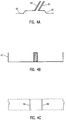
- Figures 4B and 4C are longitudinal views of the back and front tension members respectively.
- Figure 4B illustrates the face of tension member 43 that is in contact with the piezoelectric polymer thin film element.
- Figure 4C illustrates front tension members 44 with the metallized piezoelectric polymer thin film element partially shown in dashed lines. It is important to note that since the front and rear tension members also serve as electrical connections, each must be in contact with a metallized surface of the piezoelectric polymer thin film element. Additionally the location of the support members should be symmetrical or otherwise compensate for electrical equivalencies of their respective sensing circuit.
- FIG. 4D illustrates an alternate embodiment of shock sensor 24.
- Subassembly 25, tension members 43, 44 and electrical leads 45, 49 are each of similar composition and general manufacture as earlier described.
- Encapsulation device 33 (as shown having three elements), is comprised of an injection molded thermoplastic base member 35 for receiving the tension members 43, 44 and electrical leads 45, 49.
- Base member 35 may provide electrical shielding by including sufficient carbon or other similar functioning items in the thermoplastic composition.
- base shielding may be provided by the shielding capability of the PCB (22 in Fig 4) in which case base member 35 could be eliminated from the device with the tension members and leads directly affixed to the printed circuit board.
- a rectangular shaped, thermoplastic injected molded member 36 has dimensions complimentary to base member 35 and of height slightly in excess of mounted subassembly 25. Rectangular member 36 provides structural integrity to encapsulation device 33.
- a five sided metallic cover 37 is of slightly larger length and width dimensions than rectangular member 36 and provides a top for device 37 in addition to side and top electrical shielding.
- Protrusion 38, integral to electrical leads 49, extends away from base member 35 in an upward fashion contacting and thereby providing a ground connection for cover 37. Other grounding alternatives for cover 37 are also possible. It should also be noted that electrical leads 45, 49 and tension members 43, 44 serve as heat sinks during fabrication and mounting of the shock sensor.
- FIGs 5, 6, 7 and 8 illustrate the piezoelectric polymer film 42 contained in the shock sensor 24 in a variety of prospectives.
- Figures 7 and 8 specifically show the shock sensor deformed in response to a force, represented in the figures as an arrow or arrows.
- the shock sensor utilized in one embodiment contains a piezoelectric polymer material 42 manufactured in accordance with known prior art techniques.
- the piezoelectric polymer film used in the present invention was extruded, stretched, polarized and deposited upon a metallized substrate with segmented metallized top layers and was obtained from Atochem North America, Inc. of Valley Forge, PA.
- the piezoelectric polymer material may be comprised of polyvinylidene fluoride (PVDF) and may be manufactured of various compositions in a variety of manners as described in U.S. patents 4,946,913, 4,921,928 and 4,427,609.
- PVDF polyvinylidene fluoride
- Figure 10 depicts a block diagram of circuitry utilized for connecting the output response of shock sensor 24 to control circuitry which accordingly issues a write fault signal when signals above a predetermined threshold are detected.
- the generated signal V46 and V47 are individually amplified and compared to reference (threshold) voltages.
- the circuitry illustrated in Figure 10 is well known in the prior art and may be varied in numerous manners according to particular applications or desires.
- FIG. 6 shows the piezoelectric material 42 disposed between a metallized bottom layer 50 and metallized layers 46 and 47 on top of the piezoelectric material.
- a pair of cantilevered beams are formed, one being associated with metallized layer 46 and the other with metallized layer 47 Each beam has an associated voltage proportional to movement or stress exerted against it.
- Figure 7 illustrates deflection of the piezoelectric material upon application of force in the plane of the sensor.
- the resultant instantaneous electrical equivalent circuit for the deflection illustrated in Figure 7 is shown in Figure 11.
- Voltage along metallized layer 47 is defined as V47 and voltage along metallized layer 46 is correspondingly defined as V46.
- V47 equals V46 when no force is exerted upon the shock sensor. Accordingly, the following equations are known to be true.
- the shock sensor is oriented at a forty-five degree angle to the x, y, and z orthogonal axis of the printed circuit board and disk drive apparatus.
- the resulting device provides linear and torsional outputs for external forces applied in any direction.
- the electrical equivalent circuit of the device may be represented as a capacitor and does not have a DC content.
- the value of the capacitor is a function of piezoelectric film thickness and the metallized area. A value of 30 picofarads is typical for a device having dimensions of 0.35 inches length, 0.05 inches width and 0.028 inches thickness, similar to what has been utilized in the above described embodiment.
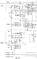
- circuitry depicted in Figure 13 may be manufactured by a variety of integrated circuit manufacturers skilled and tooled in the art of producing semi-custom or custom devices.
- SGS Thompson of Grenoble, France provided BiCMOS integrated circuit devices implementing the specific design of Figure 13 that were prepared under a proprietary agreement between SGS Thompson and Seagate Technology, Inc.
- Figure 13 depicts in dashed lines a block diagram of two input amplifiers 400 and 401, a voltage generator 240, summation amplifier 402, differencing amplifier 403, PES amplifier 404, gain setting amplifiers 405 and 406, comparator 407, set/reset flip-flop 408 and multivibrator 409.
- the component circuitry and functionality of the foregoing blocks will next be described.
- a first terminal of capacitor 100 is coupled to a common ground source.
- a second terminal of capacitor 100 is coupled to a first terminal of resistor 102 and the output of voltage to current converter 116.
- Resistor 102 has its second terminal coupled in common to a first terminal of resistor 104 and a first terminal of capacitor 106.
- Resistor 104 has a second terminal coupled to a first input of amplifier 112.
- the first input to amplifier 112 is also coupled to signal A IN .
- the output of amplifier 112 is coupled through node 300 which is coupled to resistor 114.
- Resistor 114 is coupled in turn to a second input to amplifier 112 and to node 304.
- Components 100, 102, 104, 106, 108, 110, 112, 114 and 116 comprise input amplifier 400.
- An input signal A IN is received by amplifier 112. This signal is then amplified by the closed loop gain portion of amplifier 112.
- the closed loop gain of amplifier 112 may be represented by the following equation: Equation 9)
- A112 CL A112 OL / [1 + (A112 OL ) (R114)/R110)] Where ,
- the signal at node 300 is compared to V REF by voltage to current convertor 116 and the difference converted to a current coupled to capacitor 100.
- the voltage developed on capacitor 100 is summed with the AC input signal at A IN thereby establishing the operating point for amplifier 112.
- the above described circuitry forms a self regulating amplifier having a known DC operating point.
- the AC input signal at A IN is shown in Figures 11 and 12 as comprising a voltage source coupled in series with a capacitor.
- the low frequency corner of the frequency response of the system is thereby determined by the time constant of the input impedance at A IN and the value of the shock sensor coupling capacitor. If a low frequency response of 100 Hertz is required, the resistance at A IN must be greater than 53 Megohms. This value is too large to economically be placed on a printed wiring board, therefore the signal at node 304 is fedback to the second terminal of resistor 104 through resistor 108 and capacitor 106. Since the voltage at node 304 is very close to the voltage at A IN there is very little current flow through resistor 104 thereby simulating a much larger resistance.
- Capacitor 106 is utilized for DC blocking. As the value of resistor 108 is varied the damping ratio of the closed loop low frequency response also is varied. Resistor 108 may therefore be utilized to compensate for stray impedances at A IN .
- Node 300 is also coupled through resistor 124 and into a first terminal of amplifier 134 and directly to a first input of amplifier 116.
- a second input to amplifier 116 is received from node 302.
- Capacitor 106 has a second terminal coupled through resistor 108 and to node 304.
- Node 304 is coupled through resistor 110 and 128 to a second input of amplifier 134.
- the output of amplifier 134 is coupled in common to a first terminal of resistors 136, 140 and 142.
- Resistor 136 has a second terminal coupled to the first input of amplifier 134.
- Resistor 140 has its second terminal coupled through capacitor 148 to node 306.
- Resistor 142 also has its second terminal coupled to node 306.
- Node 306 is coupled in common a first input to capacitor 152 and resistor 154 each having a second terminal coupled in common to node 307.
- Differencing amplifier 403 is comprised of resistors 124, 126, 128, 136 and amplifier 134 and measures the difference in the signals at node 300 and node 312 respectively.
- S REF signal is coupled through resistor 120 to a first input of amplifier 130.
- Node 302 is also coupled to the first input of amplifier 130 through resistor 122.
- PES signal is coupled through resistor 118 to a second input to amplifier 130.
- the output of amplifier 130 is coupled in common to a first terminal of resistor 132 and 138 respectively.
- Resistor 132 has a second terminal coupled to the second input of amplifier 130.
- Resistor 138 has a second terminal coupled to grounded capacitor 146 and through resistor 150 to a first input of comparator 158.
- a second input to comparator 158 is received from node 308.
- the output of comparator 158 is coupled to node 310.
- PES amplifier 404 is comprised of resistors 118, 120, 122, 132, 138, 150, amplifier 130 and capacitor 146. PES amplifier processes an input Signal PES received from the disk drive servo position error signal that is low passed at a frequency dependent upon the respective values of resistors 138, and 150 as well as the value of capacitor 146, thereby providing for a frequency response for external shocks that extend down to a DC signal.
- a first terminal of capacitor 200 is coupled to a common ground source.
- a second terminal of capacitor 200 is coupled to a first terminal of resistor 202 and the output of voltage to current convertor 216.
- Resistor 202 has its second terminal coupled in common to a first terminal of resistor 204 and a first terminal of capacitor 206.
- Resistor 204 has a second terminal coupled to a first input of amplifier 212.
- the first input of amplifier 212 is also coupled to signal B IN .
- the output of amplifier 212 is coupled in common to node 312 which is coupled to resistor 214 feeding back to amplifier 212 and coupled to node 314.
- input amplifier 401 The functionality of input amplifier 401 is the same as described for input amplifier 400 above and reference is herein made to the above description.
- Node 312 is also coupled through resistor 222 and into a first terminal of amplifier 224 and directly to a first input of voltage to current convertor 216.
- the first input of voltage to current convertor 216 is coupled through resistor 126 to the second input of amplifier 134.
- Resistor 220 is disposed between the first input amplifier 224 and 116 respectively.
- a second input to amplifier 216 is received from node 302.
- Capacitor 206 has a second terminal coupled through resistor 208 and to node 314.
- Node 314 is coupled through resistor 210 and 218 to a second input of amplifier 224.
- the output of amplifier 224 is coupled in common to a first terminal of resistors 226, 230 and capacitor 232.
- Resistor 226 has a second terminal coupled to the first input of amplifier 224.
- Summation amplifier 402 is comprised of resistors 220, 222, 226 and amplifier 224 and provides for the summation of the voltages at nodes 300 and 312. Resistor 218 is utilized for bias current compensation for amplifier 224.
- Resistor 230 has its second terminal coupled through node 316 to a first input of amplifier 234.
- Capacitor 232 has a second terminal coupled through resistor 233 and to node 316.
- Node 316 has a first terminal of capacitor 238 and resistor 236 coupled in common, each having a second terminal also coupled in common to node 318.
- Signal V REF is coupled from V GEN 240 to node 302.
- Signal V REF + 1 is coupled from V GEN 240 to node 320.
- Signal V REF - 1 is coupled from V GEN 240 to node 308.
- V GEN generates three DC voltages.
- the first of these voltages is V REF and is utilized as the reference voltage for the analog portions of the recorded signal thereby allowing operation with a single polarity voltage supply.
- the other two generated DC voltages are V REF + 1 and V REF - 1 , respectively representing signal V REF plus one volt and minus one volt, respectively.
- the one volt increment is arbitrary and some other voltage threshold could also be utilized.
- Node 318 is coupled to a first input of each of comparators 166 and 168.
- Node 320 is coupled to a first input of comparators 160 and 164 and to a second input of comparator 168.
- the outputs of comparators 160, 164 166 and 168 are each coupled directly to node 310.
- Comparators 158, 160, 162, 164, 166 and 168 detect when any of the input voltages differ from V REF by more than one volt. Each output of the comparators is connected in such a manner that if any one or more of these input voltage levels is outside of windows established by V REF+1 and V REF-1 a digital signal will be generated at node 310.
- Node 302 is coupled through resistor 144 to a first input of amplifier 156.
- a second input to amplifier 156 is received from node 306.
- the output of amplifier 156 is coupled through node 307 to a first input of comparator 162 and a second input of comparator 164.
- node 302 is coupled through resistor 228 to a first input of amplifier 234.
- a second input to amplifier 234 is received from node 316.
- the output of amplifier 234 is coupled to node 318.
- Gain setting amplifier 405 is comprised of resistors 140, 142, 144, 154, capacitors 148, 152 and amplifier 156. Gain setting amplifier 405 calibrates signal gains such that a known level of acceleration will result in a signal level at node 307 that is equal to one volt of displacement from signal V REF . Resistor 144 provides bias current compensation for amplifier 156, while components 140, 142, 148, and 152 each provides gain setting and frequency response shaping to match a particular application. Gain setting amplifier 406 is depicted below 405 and has similar construction and function.
- Clock signal CLK is coupled to one input of flip-flop 250.
- Flip-flop 250 has a second connection to node 324 and a third connection to a first input of OR gate 252 (a tri-stated OR gate).
- OR gate 252 has a second input coupled to signal DSPWR .
- the output of OR gate 252 is PREPWR signal and connects to control circuitry (not shown).
- Signal RFF is coupled to a first input of AND gate 244.
- the output of AND gate 244 is coupled to a first input to AND gate 246.
- a second input to AND gate 246 is received from node 310.
- Items 244 and 246 comprise a set/reset flip-flop device 408 that is active on negative going signals.
- the output of AND gate 246 is coupled in common to a first input of OR gate 248, a second input to AND gate 244 via node 326 and to control circuitry (not shown).
- Signal WRITE and signal DCFAIL provide a second and third input respectively, to OR gate 248.
- Signal WRITEG is coupled from OR gate 248 with control circuitry (not shown) for issuing a write fault signal.
- a signal 5 is coupled to a grounded capacitor 242, which is an external decoupling capacitor for the externally supplied power.
- Items 250, 252, 254 and 256 form a monostable multivibrator that is utilized for power management of the circuit as well as other portions of the disk drive circuit.
- disk drive units may be effectively operated in environments which routinely expose such drives to large external mechanical shocks.
- the present invention may be embodied in different forms without departing from the scope of the appended claims.
- the first and second members are preferably affixed to a surface of an item that the encapsulated piezoelectric device is to be mounted to thereby providing one side of the encapsulating device.
- the box shaped container is preferably metallic or metallic coated. Also in that claim, the box shaped container preferably utilizes a mounting surface to which the apparatus is to be affixed as one side of the box.
- the shock sensor preferably comprises a piezoelectric polymer film.
Landscapes
- Physics & Mathematics (AREA)
- General Physics & Mathematics (AREA)
- Supporting Of Heads In Record-Carrier Devices (AREA)
- Force Measurement Appropriate To Specific Purposes (AREA)
Abstract
Description
- This invention relates to the field of shock load detection devices. More specifically, the particular invention relates to a shock load detection device for mounting on a computer disk drive unit which senses mechanical shock imposed thereon or generated thereby and issues a signal to stop writing of the read/write heads.
- Magnetic head disk drive systems have been widely accepted in the computer industry as a cost effective form of data storage. In a magnetic disk drive system a magnetic disk rotates at high speed while a magnetic read/writes head "flies" slightly over the surface of the rotating disk. The magnetic disk is rotated by means of a spindle drive motor. The magnetic head is suspended over the disk on a spring loaded support arm known as the actuator arm. As the magnetic disk rotates at operating speed the moving air generated by the rotating disk in conjunction with the physical design of the magnetic head operate to lift the magnetic head allowing it to glide over the disk surface on a cushion of air. The flying height of the magnetic head over the disk surface is typically only a few microinches and is primarily a function of disk rotation, the aerodynamic properties of the magnetic head assembly and the force exerted by the spring-loaded actuator arm.
- Information is stored on concentric tracks of the magnetic disks. The information is transferred to or read from the disk by means of the flying magnetic head. In order to minimize destruction or distortion of the stored data on the disk, it is necessary that the flying head remain substantially centered on a given track during the write process. A mechanical shock introduced to the system can force the head away from the track center, sometimes into adjacent tracks. If this occurs during write not only is data on the current track corrupted, but data on adjacent tracks may be corrupted. With the introduction of disk drives into portable computers, resistance to shocks or compensation for its effects becomes increasingly important. Prior resistance measures include balancing rotary actuators so that X, Y or Z aligned orthogonal forces exerted on the balanced actuator in response to shock are minimized. However, even balanced actuators are susceptible to rotational (twisting) shock.
- Prior compensation methods include disabling write in response to the detection of an off-track condition. This method may be imperfect because indication of a shock may come too late to prevent a write error. Furthermore, the shock may cause a data head position error without any servo head position error detected.
- Other prior compensation techniques involve the incorporation of shock sensors in a drive. These sensors generally utilize piezoelectric crystal material as described and set forth in U.S. patent 4,862,298, incorporated herein by reference. Prior art shock sensors have two notable deficiencies. First, they do not adequately address rotational shock nor are they low cost.
- The need for a reliable shock sensor element in disk drives is particularly critical in lap-top and notebook computers. These computers are routinely subjected to operating shocks far in excess of desk top or mainframe applications. The technique set forth in U.S. patent 4,862,298 does not present a viable or feasible option for small drives associated with lap-top and notebook computers both because of insufficient sensitivity to rotational shock and because of its high cost.
- In recent years piezoelectric pressure sensitive elements have found utilization in many applications. Piezoelectric effect is a well known phenomenon which produces an electric impulse in response to pressure applied to piezoelectric sensitive material. Piezoelectric material, as known in the prior art, may utilize dielectric polarization along a known direction of the piezoelectric polymer. Connectors for electronic circuitry are affixed to the piezoelectric material. In response to an applied pressure, an electronic signal is generated and processed through control circuitry.
- Piezoelectric polymer materials may be polyvinylidene fluoride (PVDF), copolymers of vinylidene fluoride and trifluoroethylene (VDF/TrFE), copolymers of vinylidene fluoride and tetrafluoroethylene (VDF/TeFE) or copolymers of vinylidene cyanide and vinyl acetate (VDCN/VA). These materials have a variety of manufacturing processes described and well known in the prior art and specifically described in U.S. patents 4,946,913, 4,921,928, and 4,427,609 all incorporated herein by reference. The known prior art fails to teach use of piezoelectric polymers to provide torsional force measurement exerted upon a disk drive machine to issue a write signal.
- The present invention provides a shock load detection device to detect mechanical shock on a disk drive machine. The shock load detector device is designed to fit within the disk drive housing and is capable of monitoring shocks up to 1,000 G's. A "G" is a measurement of acceleration of gravity.
- The shock sensor of the present invention utilizes a piezoelectric polymer material mounted within an electrically shielded case which is then mounted at a forty-five degree angle to the read/write surface of the information storage disk of the disk drive. One embodiment of the current invention is to mechanically orient the transducer at a forty-five degree angle to each of the three mutually orthogonal axis (x, y and z) in the coordinate system. The resultant output of the shock sensor provides a signal that can be used for generating a write fault signal to the disk drive independent of the accelerating force direction.
- It is therefore an object of the present invention to provide an apparatus for issuing a stop write signal when excessive acceleration is detected.
- A feature of the present invention is utilization of a piezoelectric polymer or copolymer to sense external forces on the disk drive.
- An advantage of the present invention is an economical shock sensor comprised in part of a single piezoelectric polymer film that detects applied forces and issues a write fault signal that may be either torsional or linear in nature.
- These and other objects, advantages and features of the present invention will become apparent to those skilled in the art after having read the following disclosure of an embodiment and which is illustrated in the following figures, in which:-
- FIGURE 1 is an exploded isometric view of the base cover and printed circuit board of disk drive, as known in the prior art.
- FIGURE 2 is a plan view of a disk drive with the top cover removed, as known in the prior art.
- FIGURE 3 is an isometric view of a printed circuit board of a disk drive with a shock sensor of the present invention mounted thereon.
- FIGURE 4 is a partial isometric view of a printed circuit board having an embodiment of the present invention with its cover removed.
- FIGURE 4A is a cross-sectional view of the tension members and electrical leads of the present invention.
- FIGURES 4B and 4C are longitudinal views of the back and front tension members respectively.
- FIGURE 4D is an exploded isometric view of an alternate embodiment of the packaged present invention.
- FIGURE 5 is a top view of the piezoelectric polymer of the present invention removed from its package.
- FIGURE 6 is a side view of the piezoelectric polymer of the present invention removed from its package.
- FIGURE 7 is a side view of the piezoelectric polymer of the present invention removed from its package and distorted by an exerted force.
- FIGURE 8 is a side view of the piezoelectric polymer of the present invention removed from its package and distorted in a torsional fashion.
- FIGURE 9 is a view of the piezoelectric polymer of the present invention depicted in a forty-five degree angle to the x, y, and z axis of the orthogonal coordinate system.
- FIGURE 10 is a block diagram of bootstrapping electrical circuitry for connecting the shock sensor of the present invention to control circuitry.
- FIGURE 11 is a block diagram of illustrating the electrical equivalent of the shock sensor of Figure 7.
- FIGURE 12 is a block diagram illustrating the electrical equivalent of the shock sensor of Figure 8.
- FIGURE 13 is a schematic circuity diagram for connecting the transducer of the present invention to control circuitry.
- With reference to Figure 1, a
disk drive 10 is illustrated and exploded in isometric format. The components particularly noted are atop cover 12, anactuator 14, amagnetic head 16,spindle motor 18,bottom cover 20 and a printedcircuit board 22. The printedcircuit board 22 is depicted in a fashion populated with integrated circuit devices for controlling disk drive operations. - Figure 2 is a top plan view of a typical disk drive machine and may be considered the disk drive of Figure 1. The top casing has been removed and provides a better view of
actuator 14,magnetic head 16, andinformation storage disk 26. Although only one information storage disk is illustrated it should be noted that disk drive machines may be comprised of a plurality of such disks and this illustration is not to be considered a limitation with respect to disk drive machines on which the present invention may operate. - As shown in Figure 2, the
actuator 14 is a voice coil motor (VCM) and is connected to themagnetic head 16 byactuator arm 28,pivotally mounted toshaft 30.Control circuitry 32 is connected to the actuator arm and VCM for generating enabling signals and thereby controlling movement of themagnetic head 16 across the magneticinformation storage disk 26 in an arcuate fashion. - Figure 3 illustrates a printed circuit board of a disk drive embodying a piezoelectric shock sensor of the
present invention 24.Device 24 on printedcircuit board 22 represents an electrically shielded piezoelectric polymer film having electrical connections for sensing shock loads generated by or applied todisk drive 10. The shock sensor may be mounted in such a manner that the plane of the sensor intersects the x, y and z axis of the printed circuit/drive board 22 (Figure 3) at an angle of forty-five degrees. Orientation ofshock sensor 24 in this manner allows for maximum sensitivity of the planar sensor to both torsional and linear forces applied to the disk drive device. - Additional
control circuitry devices 34 and 34' populate the depicted board and may consist of a variety of memory, analog/digital or digital/analog functions. -
Device 24 may be applied to printedcircuit board 22 by any of a variety of methods such as soldering or gluing. Care must be used when mountingdevice 24 to board 22 so that the device is not exposed to temperatures in excess of those recommended by the piezoelectric polymer manufacturer. Piezoelectric polymers that are more tolerant of higher temperatures may be utilized to compensate for specific packaging, mounting or other manufacturing techniques. - Figure 4 is a partial isometric view of the printed
circuit board 22 depicted and described in Figure 3.Shock sensor 24 is shown in an electrically shieldedcase 41, having its top 40 removed, thereby exposingsubassembly 25 comprised of apiezoelectric polymer film 42 disposed between topmetallized layers Metallized layers film 42 by a variety of manufacturing processes and in one embodiment each layer was comprised of aluminum that was sputtered onfilm 42.Layer 50 may be any common substrate and in one embodiment was comprised of beryllium copper.Subassembly 25 is rigidly mounted by way of tension members 44 (andtension members 43, shown in Figures 4A and 4B) havingelectrical leads 45 extending therefrom (Electrical leads 49 extend from tension members 43).Tension members - Figure 4 further illustrates that the relatively planar shock sensor is mounted in such a manner that the plane of the sensor intersects the x, y and z axis of the printed circuit/drive board 22 (Figure 3) at an angle of forty-five degrees. Orientation of
shock sensor 24 in this manner allows for maximum sensitivity of the planar sensor to both torsional and linear forces applied to the disk drive device. - Figure 4A is a cross-sectional view of front and
rear tension members electrical leads tension members Electrical lead 45 is an integral part oftension member 43, extending away from the adjacent surface of the piezoelectric polymer thin film element. In like fashion,electrical lead 49 is integral to and extends away fromtension member 44. - Figures 4B and 4C are longitudinal views of the back and front tension members respectively. Figure 4B illustrates the face of
tension member 43 that is in contact with the piezoelectric polymer thin film element. Similarly, Figure 4C illustratesfront tension members 44 with the metallized piezoelectric polymer thin film element partially shown in dashed lines. It is important to note that since the front and rear tension members also serve as electrical connections, each must be in contact with a metallized surface of the piezoelectric polymer thin film element. Additionally the location of the support members should be symmetrical or otherwise compensate for electrical equivalencies of their respective sensing circuit. - Figure 4D illustrates an alternate embodiment of
shock sensor 24.Subassembly 25,tension members electrical leads thermoplastic base member 35 for receiving thetension members electrical leads Base member 35 may provide electrical shielding by including sufficient carbon or other similar functioning items in the thermoplastic composition. Alternatively, base shielding may be provided by the shielding capability of the PCB (22 in Fig 4) in whichcase base member 35 could be eliminated from the device with the tension members and leads directly affixed to the printed circuit board. A rectangular shaped, thermoplastic injected moldedmember 36 has dimensions complimentary tobase member 35 and of height slightly in excess of mountedsubassembly 25.Rectangular member 36 provides structural integrity toencapsulation device 33. A five sidedmetallic cover 37 is of slightly larger length and width dimensions thanrectangular member 36 and provides a top fordevice 37 in addition to side and top electrical shielding.Protrusion 38, integral toelectrical leads 49, extends away frombase member 35 in an upward fashion contacting and thereby providing a ground connection forcover 37. Other grounding alternatives forcover 37 are also possible. It should also be noted that electrical leads 45, 49 andtension members - Figures 5, 6, 7 and 8 illustrate the
piezoelectric polymer film 42 contained in theshock sensor 24 in a variety of prospectives. Figures 7 and 8 specifically show the shock sensor deformed in response to a force, represented in the figures as an arrow or arrows. The shock sensor utilized in one embodiment contains apiezoelectric polymer material 42 manufactured in accordance with known prior art techniques. The piezoelectric polymer film used in the present invention was extruded, stretched, polarized and deposited upon a metallized substrate with segmented metallized top layers and was obtained from Atochem North America, Inc. of Valley Forge, PA. The piezoelectric polymer material may be comprised of polyvinylidene fluoride (PVDF) and may be manufactured of various compositions in a variety of manners as described in U.S. patents 4,946,913, 4,921,928 and 4,427,609. - Figure 10 depicts a block diagram of circuitry utilized for connecting the output response of
shock sensor 24 to control circuitry which accordingly issues a write fault signal when signals above a predetermined threshold are detected. The generated signal V₄₆ and V₄₇ are individually amplified and compared to reference (threshold) voltages. The circuitry illustrated in Figure 10 is well known in the prior art and may be varied in numerous manners according to particular applications or desires. - Up until now the physical construction of the disk drive incorporating the piezoelectric shock sensor of the present invention has been described in detail. The functionality of the device will now be described. One embodiment of the shock sensor is illustrated in Figure 6 and shows the
piezoelectric material 42 disposed between a metallizedbottom layer 50 and metallizedlayers layer 46 and the other with metallizedlayer 47 Each beam has an associated voltage proportional to movement or stress exerted against it. - Figure 7 illustrates deflection of the piezoelectric material upon application of force in the plane of the sensor. The resultant instantaneous electrical equivalent circuit for the deflection illustrated in Figure 7 is shown in Figure 11. Voltage along metallized
layer 47 is defined as V₄₇ and voltage along metallizedlayer 46 is correspondingly defined as V₄₆. V₄₇ equals V₄₆ when no force is exerted upon the shock sensor. Accordingly, the following equations are known to be true. - LINEAR SHOCK
-


- TORSIONAL SHOCK
-


- In one embodiment of the present invention, such as Figures 4 and 9, the shock sensor is oriented at a forty-five degree angle to the x, y, and z orthogonal axis of the printed circuit board and disk drive apparatus. The resulting device provides linear and torsional outputs for external forces applied in any direction.
- The electrical equivalent circuit of the device may be represented as a capacitor and does not have a DC content. The value of the capacitor is a function of piezoelectric film thickness and the metallized area. A value of 30 picofarads is typical for a device having dimensions of 0.35 inches length, 0.05 inches width and 0.028 inches thickness, similar to what has been utilized in the above described embodiment.
- External forces proportional to the dimensions of the shock sensor for small disk drive units generate low frequency signals. For low frequency response, a load impedance must be very high in order for the sensor device to be functional. An
amplification circuit


Where - S =
- the LaPlacian operator
- VA=
- the voltage at A
- VB=
- the voltage at B
- The circuitry depicted in Figure 13 may be manufactured by a variety of integrated circuit manufacturers skilled and tooled in the art of producing semi-custom or custom devices. For purposes of the present invention SGS Thompson of Grenoble, France provided BiCMOS integrated circuit devices implementing the specific design of Figure 13 that were prepared under a proprietary agreement between SGS Thompson and Seagate Technology, Inc.
- Figure 13 depicts in dashed lines a block diagram of two
input amplifiers voltage generator 240,summation amplifier 402, differencingamplifier 403,PES amplifier 404, gain settingamplifiers comparator 407, set/reset flip-flop 408 andmultivibrator 409. The component circuitry and functionality of the foregoing blocks will next be described. - A first terminal of
capacitor 100 is coupled to a common ground source. A second terminal ofcapacitor 100 is coupled to a first terminal ofresistor 102 and the output of voltage tocurrent converter 116.Resistor 102 has its second terminal coupled in common to a first terminal ofresistor 104 and a first terminal ofcapacitor 106.Resistor 104 has a second terminal coupled to a first input ofamplifier 112. The first input toamplifier 112 is also coupled to signal AIN. The output ofamplifier 112 is coupled throughnode 300 which is coupled toresistor 114.Resistor 114 is coupled in turn to a second input toamplifier 112 and tonode 304. -
Components input amplifier 400. An input signal AIN is received byamplifier 112. This signal is then amplified by the closed loop gain portion ofamplifier 112. The closed loop gain ofamplifier 112 may be represented by the following equation:

Where , - A112CL =
- value of the closed loop gain of
amplifier 112 - A112OL =
- value of the open loop gain of
amplifier 112 - R114 =
- the value of
resistor 114 - R110 =
- the value of
resistor 110. - The signal at
node 300 is compared to VREF by voltage tocurrent convertor 116 and the difference converted to a current coupled tocapacitor 100. The voltage developed oncapacitor 100 is summed with the AC input signal at AIN thereby establishing the operating point foramplifier 112. The above described circuitry forms a self regulating amplifier having a known DC operating point. - The AC input signal at AIN is shown in Figures 11 and 12 as comprising a voltage source coupled in series with a capacitor. The low frequency corner of the frequency response of the system is thereby determined by the time constant of the input impedance at AIN and the value of the shock sensor coupling capacitor. If a low frequency response of 100 Hertz is required, the resistance at AIN must be greater than 53 Megohms. This value is too large to economically be placed on a printed wiring board, therefore the signal at
node 304 is fedback to the second terminal ofresistor 104 throughresistor 108 andcapacitor 106. Since the voltage atnode 304 is very close to the voltage at AIN there is very little current flow throughresistor 104 thereby simulating a much larger resistance. The effective resistance value ofresistor 104 may be expressed as follows:

Where, - R104EFF =
- effective value of
resistor 104 - R104ACT =
- actual value of
resistor 104 - A112OL =
- value of the open loop gain of
amplifier 112 - R114 =
- the value of
resistor 114 - R110 =
- the value of
resistor 110. -
Capacitor 106 is utilized for DC blocking. As the value ofresistor 108 is varied the damping ratio of the closed loop low frequency response also is varied.Resistor 108 may therefore be utilized to compensate for stray impedances at AIN. -
Node 300 is also coupled throughresistor 124 and into a first terminal ofamplifier 134 and directly to a first input ofamplifier 116. A second input toamplifier 116 is received fromnode 302.Capacitor 106 has a second terminal coupled throughresistor 108 and tonode 304.Node 304 is coupled throughresistor amplifier 134. The output ofamplifier 134 is coupled in common to a first terminal ofresistors Resistor 136 has a second terminal coupled to the first input ofamplifier 134.Resistor 140 has its second terminal coupled throughcapacitor 148 tonode 306.Resistor 142 also has its second terminal coupled tonode 306.Node 306 is coupled in common a first input tocapacitor 152 andresistor 154 each having a second terminal coupled in common tonode 307. -
Differencing amplifier 403, is comprised ofresistors amplifier 134 and measures the difference in the signals atnode 300 and node 312 respectively. - S REF signal is coupled through
resistor 120 to a first input ofamplifier 130.Node 302 is also coupled to the first input ofamplifier 130 throughresistor 122. PES signal is coupled throughresistor 118 to a second input toamplifier 130. The output ofamplifier 130 is coupled in common to a first terminal ofresistor Resistor 132 has a second terminal coupled to the second input ofamplifier 130.Resistor 138 has a second terminal coupled to groundedcapacitor 146 and throughresistor 150 to a first input ofcomparator 158. A second input tocomparator 158 is received fromnode 308. The output ofcomparator 158 is coupled tonode 310. -
PES amplifier 404, is comprised ofresistors amplifier 130 andcapacitor 146. PES amplifier processes an input Signal PES received from the disk drive servo position error signal that is low passed at a frequency dependent upon the respective values ofresistors capacitor 146, thereby providing for a frequency response for external shocks that extend down to a DC signal. - A first terminal of
capacitor 200 is coupled to a common ground source. A second terminal ofcapacitor 200 is coupled to a first terminal ofresistor 202 and the output of voltage tocurrent convertor 216.Resistor 202 has its second terminal coupled in common to a first terminal ofresistor 204 and a first terminal ofcapacitor 206.Resistor 204 has a second terminal coupled to a first input ofamplifier 212. The first input ofamplifier 212 is also coupled to signal BIN. The output ofamplifier 212 is coupled in common to node 312 which is coupled to resistor 214 feeding back toamplifier 212 and coupled tonode 314. - The functionality of
input amplifier 401 is the same as described forinput amplifier 400 above and reference is herein made to the above description. - Node 312 is also coupled through resistor 222 and into a first terminal of
amplifier 224 and directly to a first input of voltage tocurrent convertor 216. The first input of voltage tocurrent convertor 216 is coupled throughresistor 126 to the second input ofamplifier 134.Resistor 220 is disposed between thefirst input amplifier amplifier 216 is received fromnode 302.Capacitor 206 has a second terminal coupled throughresistor 208 and tonode 314.Node 314 is coupled throughresistor amplifier 224. The output ofamplifier 224 is coupled in common to a first terminal ofresistors capacitor 232.Resistor 226 has a second terminal coupled to the first input ofamplifier 224. -
Summation amplifier 402 is comprised ofresistors amplifier 224 and provides for the summation of the voltages atnodes 300 and 312.Resistor 218 is utilized for bias current compensation foramplifier 224. -
Resistor 230 has its second terminal coupled throughnode 316 to a first input ofamplifier 234.Capacitor 232 has a second terminal coupled throughresistor 233 and tonode 316.Node 316 has a first terminal ofcapacitor 238 andresistor 236 coupled in common, each having a second terminal also coupled in common tonode 318. Signal VREF is coupled fromV GEN 240 tonode 302. Signal VREF + 1 is coupled fromV GEN 240 tonode 320. Signal VREF - 1 is coupled fromV GEN 240 tonode 308. VGEN generates three DC voltages. The first of these voltages is VREF and is utilized as the reference voltage for the analog portions of the recorded signal thereby allowing operation with a single polarity voltage supply. The other two generated DC voltages are VREF + 1 and VREF - 1, respectively representing signal VREF plus one volt and minus one volt, respectively. The one volt increment is arbitrary and some other voltage threshold could also be utilized. -
Node 318 is coupled to a first input of each ofcomparators Node 320 is coupled to a first input ofcomparators comparator 168. The outputs ofcomparators node 310. -
Comparators node 310. -
Node 302 is coupled throughresistor 144 to a first input ofamplifier 156. A second input toamplifier 156 is received fromnode 306. The output ofamplifier 156 is coupled throughnode 307 to a first input ofcomparator 162 and a second input ofcomparator 164. Additionally,node 302 is coupled throughresistor 228 to a first input ofamplifier 234. A second input toamplifier 234 is received fromnode 316. The output ofamplifier 234 is coupled tonode 318. - Gain setting
amplifier 405 is comprised ofresistors capacitors amplifier 156. Gain settingamplifier 405 calibrates signal gains such that a known level of acceleration will result in a signal level atnode 307 that is equal to one volt of displacement from signal VREF. Resistor 144 provides bias current compensation foramplifier 156, whilecomponents amplifier 406 is depicted below 405 and has similar construction and function. - Clock signal CLK is coupled to one input of flip-
flop 250. Flip-flop 250 has a second connection tonode 324 and a third connection to a first input of OR gate 252 (a tri-stated OR gate). ORgate 252 has a second input coupled to signal DSPWR. The output of ORgate 252 is PREPWR signal and connects to control circuitry (not shown). - Signal RFF is coupled to a first input of AND
gate 244. The output of ANDgate 244 is coupled to a first input to ANDgate 246. A second input to ANDgate 246 is received fromnode 310.Items flop device 408 that is active on negative going signals. The output of ANDgate 246 is coupled in common to a first input of OR gate 248, a second input to ANDgate 244 vianode 326 and to control circuitry (not shown). Signal WRITE and signal DCFAIL provide a second and third input respectively, to OR gate 248. Signal WRITEG is coupled from OR gate 248 with control circuitry (not shown) for issuing a write fault signal. - A
signal 5 is coupled to a groundedcapacitor 242, which is an external decoupling capacitor for the externally supplied power. -
Items - By utilizing the teachings of the present invention, disk drive units may be effectively operated in environments which routinely expose such drives to large external mechanical shocks. The present invention may be embodied in different forms without departing from the scope of the appended claims.
- In claim 8 of the following claims, the first and second members are preferably affixed to a surface of an item that the encapsulated piezoelectric device is to be mounted to thereby providing one side of the encapsulating device.
- In claim 9 of the following claims, the box shaped container is preferably metallic or metallic coated. Also in that claim, the box shaped container preferably utilizes a mounting surface to which the apparatus is to be affixed as one side of the box.
- In
claim 10 of the following claims, the shock sensor preferably comprises a piezoelectric polymer film.
When an external force is applied in such a manner to produce torque, deflection of the piezoelectric sensor may be as shown in Figure 8. The resulting instantaneous electrical circuit for torque deflection of the shock sensor is depicted in Figure 12. By utilizing the assumptions set forth in the above equations, the shock sensor may serve as a device in which simple addition or subtraction of output voltages or signals can provide information regarding the magnitude, direction and torsional information of any applied force. By varying the mechanical orientation of the transducer, forces of a variety of planes and torsions may be monitored or sensed.
Claims (9)
- A shock load detection device mounted on a disk drive unit comprising:
a relatively planar shock sensor (24) mounted on a relatively rectangular disk drive (10) such that the plane of the sensor (24) intersects the planes aligned with the sides of the disk drive (10) at oblique angles. - The apparatus of claim 1, wherein the sensor (24) comprises a piezoelectric polymer film (42).
- The apparatus of claim 2, further comprised of:
amplifier means (52,54) connected to the sensor means (24) for producing a voltage signal proportional to the electrical charge received from the sensor means (24); and
comparator means connected to the amplifier means (52, 54) for evaluating the voltage signal to a predetermined threshold voltage, corresponding to a known acceleration level, and issuing a write-fault signal to suspend magnetic recording, when the voltage signal received by the comparator means exceeds the predetermined threshold voltage. - The apparatus of claim 2, further comprising a metallic case (41) encapsulating the piezoelectric polymer film (42) for electrical shielding purposes.
- The apparatus of claim 2, further comprising a case (41) having a metallized coating encapsulating the piezoelectric polymer film (42) for electrical shielding purposes.
- The apparatus of claim 2 mounted on the drive (10) in such a manner so that the piezoelectric polymer film (42) rests approximately 45° to the x, y and z axis of the orthogonal co-ordinate system.
- The apparatus of claim 2 wherein the piezoelectric polymer film (42) is mounted within a metallic case (41) at a 45° angle longitudinally.
- An apparatus for protecting a disk drive from the effects of shock comprising:
a relatively planar shock sensor; and
means for mounting the sensor of the disk drive in a manner so that the sensor is relatively sensitive to shocks in all three dimensions and to rotational shock. - An apparatus as claimed in claim 8, wherein the sensor comprises a piezoelectric film within an encapsulating device; and wherein the means for mounting the sensor comprises a first and a second member each having a first end affixed to said encapsulating devices; and a second end having a plurality of projections extending away from the first end of the respective member and arranged such that the projections of one member are all within a single geometrical plane, the planes within which the projections lie being approximately parallel to each other and spaced apart a distance slightly less than the piezoelectric film assembly thickness.
Applications Claiming Priority (2)
| Application Number | Priority Date | Filing Date | Title |
|---|---|---|---|
| US07/779,214 US5235472A (en) | 1991-10-18 | 1991-10-18 | Apparatus for sensing operating shock on a disk drive |
| US779214 | 1991-10-18 |
Publications (2)
| Publication Number | Publication Date |
|---|---|
| EP0538976A1 true EP0538976A1 (en) | 1993-04-28 |
| EP0538976B1 EP0538976B1 (en) | 1998-09-30 |
Family
ID=25115692
Family Applications (1)
| Application Number | Title | Priority Date | Filing Date |
|---|---|---|---|
| EP92302495A Expired - Lifetime EP0538976B1 (en) | 1991-10-18 | 1992-03-24 | Apparatus for sensing operating shock on a disk drive |
Country Status (6)
| Country | Link |
|---|---|
| US (2) | US5235472A (en) |
| EP (1) | EP0538976B1 (en) |
| JP (1) | JP3153860B2 (en) |
| DE (2) | DE69227167T2 (en) |
| HK (1) | HK1013726A1 (en) |
| SG (1) | SG48085A1 (en) |
Cited By (7)
| Publication number | Priority date | Publication date | Assignee | Title |
|---|---|---|---|---|
| EP0655736A2 (en) * | 1993-11-30 | 1995-05-31 | International Business Machines Corporation | Disk drive with acceleration rate sensing |
| EP0658894A1 (en) * | 1993-12-15 | 1995-06-21 | Hewlett-Packard Company | Disk drive and method for minimizing shock-induced damage |
| EP0735522A1 (en) * | 1995-03-27 | 1996-10-02 | Hewlett-Packard Company | Disk data recording and reproducing device |
| WO1997009622A1 (en) * | 1995-09-07 | 1997-03-13 | The Whitaker Corporation | Polyaxial acceleration sensor beam |
| EP0768533A1 (en) * | 1995-10-11 | 1997-04-16 | SOCIETE NATIONALE D'ETUDE ET DE CONSTRUCTION DE MOTEURS D'AVIATION -Snecma | Differential charge amplifier for piezoelectric sensor |
| WO1999014602A1 (en) * | 1997-09-17 | 1999-03-25 | Aeptec Microsystems, Inc. | Piezoelectric shock sensor |
| GB2380047A (en) * | 2001-09-21 | 2003-03-26 | Hewlett Packard Co | Data storage cartridge with sensor |
Families Citing this family (62)
| Publication number | Priority date | Publication date | Assignee | Title |
|---|---|---|---|---|
| US5227929A (en) * | 1990-11-26 | 1993-07-13 | International Business Machines Corporation | Portable computer hard disk protective reflex system |
| DE69226519T2 (en) * | 1991-12-23 | 1999-02-04 | Atochem North America Elf | ACCELEROMETER WITH SEVERAL VIBRATION TYPES |
| US5327303A (en) * | 1992-12-18 | 1994-07-05 | Seagate Technology, Inc. | MR preamplifier having feedback loops for minimizing differential low frequency components and regulating common mode low frequency components of the preamplifier output signal |
| US5729397A (en) * | 1992-12-31 | 1998-03-17 | International Business Machines Corporation | System and method for recording direct access storage device operating statistics |
| WO1994022135A1 (en) * | 1993-03-23 | 1994-09-29 | Ministor Peripheral International Limited | Ultra-small form factor disk drive apparatus |
| US5495137A (en) * | 1993-09-14 | 1996-02-27 | The Whitaker Corporation | Proximity sensor utilizing polymer piezoelectric film with protective metal layer |
| US5696645A (en) * | 1993-10-22 | 1997-12-09 | Maxtor Corporation | Apparatus for protecting memory devices from external shock forces by using an integrating band pass filter |
| US5539270A (en) * | 1993-11-19 | 1996-07-23 | Matsushita Electric Works, Ltd. | Acceleration detector |
| US5835298A (en) * | 1996-08-16 | 1998-11-10 | Telxon Corporation | Hard drive protection system and method |
| US5426542A (en) * | 1994-01-21 | 1995-06-20 | Seagate Technology, Inc. | Electronically coupled high-impedance magnetoresistive preamplifier |
| US5654840A (en) * | 1994-06-30 | 1997-08-05 | Western Digital Corporation | Hard disk drive which uses the back EMF of the actuator to detect shocks |
| US6046877A (en) * | 1995-02-16 | 2000-04-04 | Mobile Storage Technology, Inc. | Protection apparatus and method for hard disk drive unit of a portable computer |
| US5721457A (en) * | 1995-04-28 | 1998-02-24 | International Business Machines Corporation | Shock isolation system with write inhibit |
| US5596461A (en) * | 1995-05-25 | 1997-01-21 | Seagate Technology, Inc. | Space efficient housing configuration for a disk drive #7 |
| US5828514A (en) * | 1996-02-16 | 1998-10-27 | International Business Machines Corporation | Servo error detection in a noisy environment |
| US5914630A (en) * | 1996-05-10 | 1999-06-22 | Vtc Inc. | MR head preamplifier with output signal amplitude which is independent of head resistance |
| WO1998008102A2 (en) * | 1996-08-23 | 1998-02-26 | Bang & Olufsen Technology A/S | An accelerometer |
| US5915271A (en) * | 1997-03-14 | 1999-06-22 | Seagate Techology, Inc. | Head/disc force transducer |
| US5923487A (en) * | 1997-06-05 | 1999-07-13 | Maxtor Corporation | Integrated shock sensing device |
| JPH10340522A (en) * | 1997-06-09 | 1998-12-22 | Sony Corp | Data recording device and camera device |
| US6008731A (en) * | 1997-07-30 | 1999-12-28 | Union Switch & Signal, Inc. | Detector for sensing motion and direction of a railway vehicle |
| US6285522B1 (en) | 1998-06-05 | 2001-09-04 | Seagate Technology Llc | Rotational vibration compensation using a dedicated surface with a constant frequency pattern |
| US6304406B1 (en) | 1998-06-05 | 2001-10-16 | Seagate Technology Llc | Rotational vibration compensation using a fixed head and a constant frequency pattern |
| US6088185A (en) * | 1998-06-05 | 2000-07-11 | Seagate Technology, Inc. | Rotational vibration detection using a velocity sense coil |
| US6222336B1 (en) | 1998-06-05 | 2001-04-24 | Seagate Technology Llc | Rotational vibration detection using spindle motor velocity sense coils |
| US6417979B1 (en) | 1998-10-23 | 2002-07-09 | Western Digital Technologies, Inc. | Disk drive including strain transducer for detecting mechanical shock |
| DE19857061C2 (en) * | 1998-12-10 | 2000-11-02 | Hilti Ag | Method and device for avoiding accidents in hand-held machine tools due to tool blocking |
| US6959384B1 (en) * | 1999-12-14 | 2005-10-25 | Intertrust Technologies Corporation | Systems and methods for authenticating and protecting the integrity of data streams and other data |
| US6310746B1 (en) | 1999-06-23 | 2001-10-30 | Read-Rite Corporation | Piezoelectric vibration damping for disk drives |
| US6501625B1 (en) * | 1999-06-29 | 2002-12-31 | Hutchinson Technology Incorporated | Disk drive suspension with multi-layered piezoelectric actuator controlled gram load |
| DE10084860T1 (en) | 1999-07-23 | 2002-08-01 | Seagate Technology Llc | Fault rejection for disk drives using an adaptive feedforward servo with accelerometer |
| US6496320B1 (en) | 2000-02-09 | 2002-12-17 | Seagate Technology Llc | Adaptive attenuation of multi-axis vibrational disturbance |
| JP2002048812A (en) | 2000-06-29 | 2002-02-15 | Internatl Business Mach Corp <Ibm> | Apparatus and method for measurement of shock |
| US7253982B1 (en) | 2000-08-15 | 2007-08-07 | Maxtor Corporation | Dynamic shock detection in disk drive using hair trigger timer |
| US6882489B1 (en) * | 2000-08-15 | 2005-04-19 | Maxtor Corporation | Dynamic off-track detector |
| JP2002100180A (en) * | 2000-09-22 | 2002-04-05 | Toshiba Corp | Magnetic disk unit |
| CN1470056A (en) | 2000-10-13 | 2004-01-21 | 西加特技术有限责任公司 | Suspension sense capability for windage control |
| US6807332B1 (en) | 2000-11-06 | 2004-10-19 | Western Digital (Fremont), Inc. | Piezoelectric actuated optical switch |
| KR100392635B1 (en) * | 2000-12-12 | 2003-07-23 | 삼성전자주식회사 | Actuator having shock damping device for disc drive |
| US7349174B2 (en) * | 2001-11-15 | 2008-03-25 | Seagate Technology Llc | Soft sensor for operating shock in a disc drive |
| JP3756109B2 (en) * | 2001-11-28 | 2006-03-15 | 富士通メディアデバイス株式会社 | Magnetic head support mechanism and magnetic head positioning control mechanism |
| US20040032687A1 (en) * | 2002-08-13 | 2004-02-19 | Ng Hwa Liang | Head-slap detection for a data storage device |
| US20050222801A1 (en) * | 2004-04-06 | 2005-10-06 | Thomas Wulff | System and method for monitoring a mobile computing product/arrangement |
| ITTO20040436A1 (en) | 2004-06-28 | 2004-09-28 | St Microelectronics Srl | FREE FALL DETECTION DEVICE FOR THE PROTECTION OF PORTABLE APPLIANCES. |
| KR100665840B1 (en) * | 2004-12-10 | 2007-01-09 | 삼성전자주식회사 | Memory module of daisy-chain structure and method for fabricating the same |
| JP2006172586A (en) | 2004-12-15 | 2006-06-29 | Hitachi Global Storage Technologies Netherlands Bv | Magnetic disk device |
| US7417823B2 (en) * | 2005-03-07 | 2008-08-26 | Seagate Technology Llc | Data storage device with shock sensor mounted on circuit board and provided adjacent shield and disc assembly protrusions |
| US7822513B2 (en) * | 2005-07-27 | 2010-10-26 | Symbol Technologies, Inc. | System and method for monitoring a mobile computing product/arrangement |
| US7319570B2 (en) | 2005-09-19 | 2008-01-15 | Seagate Technology Llc | Random vibration and shock compensator using a disturbance observer |
| US7751142B2 (en) * | 2006-03-22 | 2010-07-06 | Nvidia Corporation | Portable device with freefall detection or audio processing subsystem and freefall detection or audio processing method |
| US8594742B2 (en) * | 2006-06-21 | 2013-11-26 | Symbol Technologies, Inc. | System and method for monitoring a mobile device |
| US20070297028A1 (en) * | 2006-06-21 | 2007-12-27 | Thomas Wulff | System and device for monitoring a computing device |
| CN101211566B (en) * | 2006-12-30 | 2010-09-29 | 联想(北京)有限公司 | Mobile terminal and hard disk protection method |
| US7872827B2 (en) * | 2007-07-27 | 2011-01-18 | Seagate Technology Llc | Impact protection for a retractable control object |
| US7650439B2 (en) | 2007-09-10 | 2010-01-19 | Getac Technology Corporation | Falling protective device for hard disk of a portable computer |
| US20090070509A1 (en) | 2007-09-10 | 2009-03-12 | Chai-Chang Chlu | Method of detecting and protecting falling portable computer hard disk through software monitoring driver |
| US7768738B2 (en) * | 2007-11-13 | 2010-08-03 | Sensor Platforms, Inc. | Mitigating the effects of disturbances of a disk drive |
| US20100079906A1 (en) * | 2008-09-29 | 2010-04-01 | Wile Donald T | Adaptive Feed Forward Rotational Vibration Compensation During a SEEK Operation |
| JP5556210B2 (en) | 2010-02-05 | 2014-07-23 | ソニー株式会社 | Sensors and electronics |
| JPWO2011101899A1 (en) * | 2010-02-17 | 2013-06-17 | 富士通株式会社 | Information processing apparatus, protection method thereof, and protection program |
| US8537485B2 (en) | 2011-06-30 | 2013-09-17 | Seagate Technology Llc | Compensation for vibration in a data storage system |
| US10109322B1 (en) * | 2017-06-12 | 2018-10-23 | Seagate Technology Llc | Anti-shock system for a data storage device |
Citations (2)
| Publication number | Priority date | Publication date | Assignee | Title |
|---|---|---|---|---|
| EP0164642A2 (en) * | 1984-06-15 | 1985-12-18 | Matsushita Electric Industrial Co., Ltd. | Recording and reproduction apparatus |
| EP0332317A2 (en) * | 1988-03-11 | 1989-09-13 | Seagate Technology International | Shock load detection device |
Family Cites Families (26)
| Publication number | Priority date | Publication date | Assignee | Title |
|---|---|---|---|---|
| US1949149A (en) * | 1925-07-14 | 1934-02-27 | Gen Electric | Vacuum mounted oscillator |
| DE757570C (en) * | 1937-04-15 | 1953-09-14 | Siemens & Halske A G | Holder for oscillating crystals |
| GB538002A (en) * | 1940-04-05 | 1941-07-16 | Automatic Telephone & Elect | Improvements in or relating to piezo electric crystals |
| US2326923A (en) * | 1941-09-30 | 1943-08-17 | Rca Corp | Art of mounting piezoelectric crystals |
| US2392690A (en) * | 1942-10-01 | 1946-01-08 | Simmonds Aerocessories Ltd | Piezoelectric crystal holder |
| US2380592A (en) * | 1944-07-08 | 1945-07-31 | Herman L Gordon | Piezoelectric crystal holder |
| US2383262A (en) * | 1944-09-16 | 1945-08-21 | Walter E Kuenstler | Crystal |
| US2384757A (en) * | 1944-11-15 | 1945-09-11 | Walter E Kuenstler | Crystal holder |
| FR939044A (en) * | 1946-03-29 | 1948-11-02 | Int Standard Electric Corp | Piezoelectric crystal mounts |
| US2464046A (en) * | 1947-10-18 | 1949-03-08 | Walter E Kuenstler | Crystal holder |
| US2814741A (en) * | 1955-02-10 | 1957-11-26 | Standard Electronics Corp | Crystal mounting means |
| US3304787A (en) * | 1962-12-29 | 1967-02-21 | Toyoda Chuo Kenkyusho Kk | Three-dimensional accelerometer device |
| US3363471A (en) * | 1964-06-25 | 1968-01-16 | Endevco Corp | Accelerometer |
| JPS5027869Y1 (en) * | 1970-05-13 | 1975-08-18 | ||
| US3622816A (en) * | 1970-06-12 | 1971-11-23 | Electro Dynamics | Piezoelectric crystal assembly |
| AT375466B (en) * | 1977-07-27 | 1984-08-10 | List Hans | MEASURING VALUE WITH A PIEZOELECTRIC MEASURING ELEMENT |
| JPS5525278A (en) * | 1978-08-12 | 1980-02-22 | Noto Denshi Kogyo Kk | 3-terminal type piezoelectric filter |
| JPS5718114A (en) * | 1980-07-09 | 1982-01-29 | Hitachi Ltd | Mounting method of elastic surface wave element |
| JPS5850816A (en) * | 1981-09-21 | 1983-03-25 | Tokyo Denpa Kk | Crystal oscillator |
| US4431938A (en) * | 1981-12-09 | 1984-02-14 | Murata Manufacturing Co., Ltd. | Grooved piezoelectric resonating element and a mounting therefore |
| DE3202394A1 (en) * | 1982-01-26 | 1983-08-04 | Standard Elektrik Lorenz Ag, 7000 Stuttgart | Holder for plate-shaped or rod-shaped piezoelectric resonators |
| US4430895A (en) * | 1982-02-02 | 1984-02-14 | Rockwell International Corporation | Piezoresistive accelerometer |
| CA1214835A (en) * | 1982-12-28 | 1986-12-02 | Murata Manufacturing Co., Ltd. | Piezoelectric resonator |
| GB2146839B (en) * | 1983-07-27 | 1987-04-01 | Nihon Dempa Kogyo Co | Piezoelectric resonator |
| KR940006950B1 (en) * | 1989-05-02 | 1994-07-30 | 후지꾸라 가부시끼가이샤 | Piezoelectric acceleration sensor and Piezoelectric acceleration sensor device |
| US5003824A (en) * | 1989-12-26 | 1991-04-02 | Matsushita Electric Industrial Co., Ltd. | Vibration/acceleration sensor |
-
1991
- 1991-10-18 US US07/779,214 patent/US5235472A/en not_active Expired - Lifetime
-
1992
- 1992-03-24 DE DE69227167T patent/DE69227167T2/en not_active Expired - Fee Related
- 1992-03-24 DE DE92302495T patent/DE538976T1/en active Pending
- 1992-03-24 EP EP92302495A patent/EP0538976B1/en not_active Expired - Lifetime
- 1992-03-24 SG SG1996006927A patent/SG48085A1/en unknown
- 1992-04-14 JP JP09453992A patent/JP3153860B2/en not_active Expired - Fee Related
-
1993
- 1993-01-27 US US08/009,508 patent/US5373213A/en not_active Expired - Lifetime
-
1998
- 1998-12-23 HK HK98115058A patent/HK1013726A1/en not_active IP Right Cessation
Patent Citations (2)
| Publication number | Priority date | Publication date | Assignee | Title |
|---|---|---|---|---|
| EP0164642A2 (en) * | 1984-06-15 | 1985-12-18 | Matsushita Electric Industrial Co., Ltd. | Recording and reproduction apparatus |
| EP0332317A2 (en) * | 1988-03-11 | 1989-09-13 | Seagate Technology International | Shock load detection device |
Non-Patent Citations (1)
| Title |
|---|
| PATENT ABSTRACTS OF JAPAN, unexamined applications, P field, vol. 10, no. 225, August 6, 1986 THE PATENT OFFICE JAPANESE GOVERNMENT page 122 P 484 * |
Cited By (11)
| Publication number | Priority date | Publication date | Assignee | Title |
|---|---|---|---|---|
| EP0655736A2 (en) * | 1993-11-30 | 1995-05-31 | International Business Machines Corporation | Disk drive with acceleration rate sensing |
| EP0655736A3 (en) * | 1993-11-30 | 1997-02-26 | Ibm | Disk drive with acceleration rate sensing. |
| EP0658894A1 (en) * | 1993-12-15 | 1995-06-21 | Hewlett-Packard Company | Disk drive and method for minimizing shock-induced damage |
| EP0735522A1 (en) * | 1995-03-27 | 1996-10-02 | Hewlett-Packard Company | Disk data recording and reproducing device |
| WO1997009622A1 (en) * | 1995-09-07 | 1997-03-13 | The Whitaker Corporation | Polyaxial acceleration sensor beam |
| EP0768533A1 (en) * | 1995-10-11 | 1997-04-16 | SOCIETE NATIONALE D'ETUDE ET DE CONSTRUCTION DE MOTEURS D'AVIATION -Snecma | Differential charge amplifier for piezoelectric sensor |
| FR2739936A1 (en) * | 1995-10-11 | 1997-04-18 | Snecma | DIFFERENTIAL LOAD AMPLIFIER FOR PIEZOELECTRIC SENSOR |
| US5859561A (en) * | 1995-10-11 | 1999-01-12 | Societe Nationale D'etude Et De Construction De Moteurs D'aviation "Snecma" | Differential load amplifier for piezoelectric sensors |
| WO1999014602A1 (en) * | 1997-09-17 | 1999-03-25 | Aeptec Microsystems, Inc. | Piezoelectric shock sensor |
| US6031317A (en) * | 1997-09-17 | 2000-02-29 | Aeptec Microsystems, Inc. | Piezoelecric shock sensor |
| GB2380047A (en) * | 2001-09-21 | 2003-03-26 | Hewlett Packard Co | Data storage cartridge with sensor |
Also Published As
| Publication number | Publication date |
|---|---|
| JPH05133974A (en) | 1993-05-28 |
| DE69227167T2 (en) | 1999-02-18 |
| EP0538976B1 (en) | 1998-09-30 |
| JP3153860B2 (en) | 2001-04-09 |
| US5235472A (en) | 1993-08-10 |
| DE69227167D1 (en) | 1998-11-05 |
| US5373213A (en) | 1994-12-13 |
| SG48085A1 (en) | 1998-04-17 |
| HK1013726A1 (en) | 1999-09-03 |
| DE538976T1 (en) | 1994-03-03 |
Similar Documents
| Publication | Publication Date | Title |
|---|---|---|
| EP0538976B1 (en) | Apparatus for sensing operating shock on a disk drive | |
| US6417979B1 (en) | Disk drive including strain transducer for detecting mechanical shock | |
| US4862298A (en) | Shock load detection device | |
| EP0813187B1 (en) | Disk drive with shock detection based on thermoresistive signal from magnetoresistive head | |
| JP2702418B2 (en) | Data recording disk drive | |
| US5757580A (en) | Constrain layer damping of a disc drive printed wiring assembly | |
| EP0572657B1 (en) | Multi-mode accelerometer | |
| US8611035B1 (en) | Capacitance sensor for determining a distance between a head and a magnetic storage medium | |
| US8531799B2 (en) | Head gimbal assembly with contact detection | |
| US8443672B2 (en) | Low-power shock and vibration sensors and methods of making sensors | |
| US5721457A (en) | Shock isolation system with write inhibit | |
| US7952829B2 (en) | Detecting contact between a slider and a data storage medium without a separate contact-detection voltage source | |
| KR20010052596A (en) | Rotational vibration detection using a velocity sense coil | |
| US3632900A (en) | Magnetic transducer displacement control system | |
| US4479090A (en) | Circuitry for measuring magnetic head flying characteristics | |
| JP4261468B2 (en) | Acceleration sensor | |
| CN1531728A (en) | Low amplitude skip write detector | |
| US5389850A (en) | Rotational shock sensor | |
| KR100616385B1 (en) | Acceleration sensor | |
| US8964328B1 (en) | Shock sensor on an external surface of a disk drive base adjacent a disk drive printed circuit board | |
| US20010036026A1 (en) | Efficient sensorless rotational vibration and shock compensator for hard disk drives with higher TPI | |
| US20060092543A1 (en) | System, method, and apparatus for in-situ stray magnetic field measurement | |
| JPH0680557B2 (en) | Abnormal head contact detection device for magnetic disk device | |
| JPH0191384A (en) | Thin film magnetic head assembling body | |
| WO2009157055A1 (en) | Magnetic head, head assembly, and magnetic recording device |
Legal Events
| Date | Code | Title | Description |
|---|---|---|---|
| PUAI | Public reference made under article 153(3) epc to a published international application that has entered the european phase |
Free format text: ORIGINAL CODE: 0009012 |
|
| AK | Designated contracting states |
Kind code of ref document: A1 Designated state(s): DE FR GB IT |
|
| ITCL | It: translation for ep claims filed |
Representative=s name: JACOBACCI CASETTA & PERANI S.P.A. |
|
| EL | Fr: translation of claims filed | ||
| 17P | Request for examination filed |
Effective date: 19931007 |
|
| DET | De: translation of patent claims | ||
| 17Q | First examination report despatched |
Effective date: 19951110 |
|
| GRAG | Despatch of communication of intention to grant |
Free format text: ORIGINAL CODE: EPIDOS AGRA |
|
| GRAG | Despatch of communication of intention to grant |
Free format text: ORIGINAL CODE: EPIDOS AGRA |
|
| GRAG | Despatch of communication of intention to grant |
Free format text: ORIGINAL CODE: EPIDOS AGRA |
|
| GRAH | Despatch of communication of intention to grant a patent |
Free format text: ORIGINAL CODE: EPIDOS IGRA |
|
| GRAH | Despatch of communication of intention to grant a patent |
Free format text: ORIGINAL CODE: EPIDOS IGRA |
|
| GRAH | Despatch of communication of intention to grant a patent |
Free format text: ORIGINAL CODE: EPIDOS IGRA |
|
| GRAA | (expected) grant |
Free format text: ORIGINAL CODE: 0009210 |
|
| STAA | Information on the status of an ep patent application or granted ep patent |
Free format text: STATUS: THE PATENT HAS BEEN GRANTED |
|
| AK | Designated contracting states |
Kind code of ref document: B1 Designated state(s): DE FR GB IT |
|
| PG25 | Lapsed in a contracting state [announced via postgrant information from national office to epo] |
Ref country code: IT Free format text: LAPSE BECAUSE OF FAILURE TO SUBMIT A TRANSLATION OF THE DESCRIPTION OR TO PAY THE FEE WITHIN THE PRE;WARNING: LAPSES OF ITALIAN PATENTS WITH EFFECTIVE DATE BEFORE 2007 MAY HAVE OCCURRED AT ANY TIME BEFORE 2007. THE CORRECT EFFECTIVE DATE MAY BE DIFFERENT FROM THE ONE RECORDED.SCRIBED TIME-LIMIT Effective date: 19980930 Ref country code: FR Free format text: LAPSE BECAUSE OF FAILURE TO SUBMIT A TRANSLATION OF THE DESCRIPTION OR TO PAY THE FEE WITHIN THE PRESCRIBED TIME-LIMIT Effective date: 19980930 |
|
| REF | Corresponds to: |
Ref document number: 69227167 Country of ref document: DE Date of ref document: 19981105 |
|
| EN | Fr: translation not filed | ||
| PLBE | No opposition filed within time limit |
Free format text: ORIGINAL CODE: 0009261 |
|
| 26N | No opposition filed | ||
| REG | Reference to a national code |
Ref country code: GB Ref legal event code: 732E |
|
| PGFP | Annual fee paid to national office [announced via postgrant information from national office to epo] |
Ref country code: GB Payment date: 20010219 Year of fee payment: 10 |
|
| REG | Reference to a national code |
Ref country code: GB Ref legal event code: IF02 |
|
| PG25 | Lapsed in a contracting state [announced via postgrant information from national office to epo] |
Ref country code: GB Free format text: LAPSE BECAUSE OF NON-PAYMENT OF DUE FEES Effective date: 20020324 |
|
| GBPC | Gb: european patent ceased through non-payment of renewal fee |
Effective date: 20020324 |
|
| PGFP | Annual fee paid to national office [announced via postgrant information from national office to epo] |
Ref country code: DE Payment date: 20030929 Year of fee payment: 12 |
|
| PG25 | Lapsed in a contracting state [announced via postgrant information from national office to epo] |
Ref country code: DE Free format text: LAPSE BECAUSE OF NON-PAYMENT OF DUE FEES Effective date: 20041001 |