EP0537747A2 - Oscillator circuit and proximity switch using it - Google Patents
Oscillator circuit and proximity switch using it Download PDFInfo
- Publication number
- EP0537747A2 EP0537747A2 EP92117642A EP92117642A EP0537747A2 EP 0537747 A2 EP0537747 A2 EP 0537747A2 EP 92117642 A EP92117642 A EP 92117642A EP 92117642 A EP92117642 A EP 92117642A EP 0537747 A2 EP0537747 A2 EP 0537747A2
- Authority
- EP
- European Patent Office
- Prior art keywords
- circuit
- frequency
- capacitor
- oscillator
- resistor
- Prior art date
- Legal status (The legal status is an assumption and is not a legal conclusion. Google has not performed a legal analysis and makes no representation as to the accuracy of the status listed.)
- Withdrawn
Links
Images


Classifications
-
- H—ELECTRICITY
- H03—ELECTRONIC CIRCUITRY
- H03K—PULSE TECHNIQUE
- H03K17/00—Electronic switching or gating, i.e. not by contact-making and –breaking
- H03K17/94—Electronic switching or gating, i.e. not by contact-making and –breaking characterised by the way in which the control signals are generated
- H03K17/945—Proximity switches
- H03K17/95—Proximity switches using a magnetic detector
- H03K17/952—Proximity switches using a magnetic detector using inductive coils
- H03K17/9537—Proximity switches using a magnetic detector using inductive coils in a resonant circuit
- H03K17/9542—Proximity switches using a magnetic detector using inductive coils in a resonant circuit forming part of an oscillator
- H03K17/9545—Proximity switches using a magnetic detector using inductive coils in a resonant circuit forming part of an oscillator with variable frequency
Definitions
- This invention concerns a proximity switch using high frequency oscillation to detect an object which may consist of any type of metal, and the oscillator circuit employed in this switch.
- a proximity switch which can detect any metal is described in Japanese Patent Kokai-Koho 55-72329.
- the oscillator circuit has a feedback circuit which is tuned to a frequency higher than that of the resonant circuit, producing a high impedance.
- a magnetic metal is detected using eddy current loss according to the commonly applied principle.
- a non-magnetic metal is detected via a change in oscillating frequency, which is obtained by detecting the decrease in feedback signal strength with a filter.
- proximity switches which are capable of detecting any type of metal, all require a number of coils, so it is difficult to downsize them.
- the characteristics of these coils do not allow them to remain in a fixed relationship with each other, it becomes impossible to achieve stable output characteristics.
- the necessity of using more than one coil complicates the design and makes the switch more difficult to adjust. It also makes it more difficult to lower the cost.
- an object of this invention is to provide a switch which can detect both magnetic and non-magnetic metals with the same sensitivity using a single coil.
- an oscillator circuit has a switching circuit which switches the output when the input crosses a threshold value, a series circuit with a resistor R1 and a capacitor C1, on the output side of the switching circuit, connected between the output and the ground terminal, and a series circuit with a detector coil L and a capacitor C2, which is connected in parallel to the aforementioned capacitor C1.
- the capacitance of capacitors C1 and C2 and the resistance of resistor R1 are chosen so that the change in oscillating frequency is fixed regardless of what type of metal object is approaching.
- a second embodiment of the invention has an oscillator circuit of the type described in the first embodiment, as well as a signal processing circuit which detects the distance of an object by means of the change in oscillating frequency of the oscillator circuit.
- the oscillating frequency will vary with the distance to an object regardless of what metal in contains by setting values of resistor R1 and capacitors C1 and C2 during oscillation.
- the proximity switch described in the second embodiment will detect how far away an object is by measuring a change in the oscillating frequency.
- FIG. 2 (a) shows an equivalent circuit for oscillator coil L in the oscillator circuit.
- Oscillator coil L has inductance L 1 and DC resistance r i .
- the effect of its proximity is a response equivalent to what would occur in the presence of coil L 2 and DC resistor r 2 .
- the impedance Z as seen from both terminals of the oscillator coil is given by:
- Equation 1 is divided into a real number portion and an imaginary number portion using the symbols R x and L x , the two terminals of the coil are indicated equivalently as shown in Figure 2 (b).
- the invention uses this characteristic in its design so that the change in oscillating frequency of the oscillator circuit is the same regardless of whether the approaching object is made of a magnetic or non-magnetic metal.
- Figure 1 (a) is a schematic diagram illustrating the basic structure of this invention.
- Figure 1 (a) shows a comparator or switching circuit 1.
- Reference power supply 2 which supplies voltage V th , is connected to the non-inverting input terminal of the comparator 1.
- the output of comparator 1 returns to ground through the series connection of resistor R 1 and capacitor C 1 .
- the midpoint of this network returns to ground through the series connection of oscillator coil L and capacitor C 2 .
- the midpoint between oscillator coil L and capacitor C 2 is connected to the inverting input terminal of comparator 1.
- Figure 1 (b) when object 3 approaches, oscillator coil L functions just as in Figure 2 (a).
- the effects on Li, ri of object 3 are represented by inductance L 2 and resistance r 2 . This being the case, the effect of object 3 is represented as shown in Figure 1 (c), as was discussed above with respect to Figures 2a and 2b.
- Comparator 1 is a switching circuit which outputs a high or low level signal. This can be represented by switch 4 in the equivalent circuit in Figure 3.
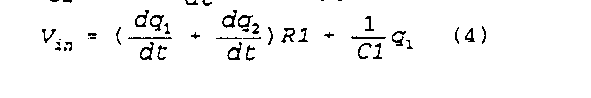
- V in can then be expressed as follows.
- V in 0
- the oscillating frequency ⁇ ose can be expressed by the following formula.
- L x is in the denominator in Formula (9), and R x is in the numerator.
- R x is in the numerator.
- the oscillating frequency will increase because of the increase in R x ; when a non-magnetic metal approaches, the frequency will increase because of the decrease in L x .
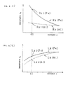
- FIGs 4 (a) and (b) graphically illustrate how resistance R x and inductance L x vary with the distance, d, for a magnetic metal (iron) and a non-magnetic metal (aluminum). As can be seen in the graphs, the resistance and inductance both vary as exponential functions, differing only in their coefficients for the different materials.
- the values of capacitors C 1 and C 2 and resistor R 1 are determined as follows. Capacitors C 1 and C 2 and corresponding oscillator coil L form the oscillator circuit of the proximity switch. They are selected so as to provide a suitable oscillating frequency. Call the resistance value for iron at a specified distance, di, R x1 (Fe), and that for aluminum R x1 (Al). Then call the inductance for iron at the same distance L x1 (Fe) and that for aluminum L x1 (Al). A frequency equivalent to the oscillating frequency at this time can be obtained by employing Formula 10.
- the equation can be solved in the same fashion as Formula (10) for distances other than di, say d 2 and d 3 , and the values for capacitors C 1 and C 2 and resistor R 1 can be determined by simultaneous equations. In this way the characteristics can be made to coincide perfectly.
- this scheme does not allow the user to freely choose an oscillating frequency, which suggests that it would not be appropriate for a proximity switch. For this reason, we have chosen an example in which Formula (10) is established for one specified distance d 1 . Appropriate values for C 1 and C 2 are selected, and an oscillating frequency is chosen. The characteristic rates of change of oscillating frequency corresponding to different types of metals are made to be very similar.
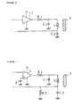
- Figure 6 is a second circuit diagram of an oscillator circuit which might be used in the first embodiment.
- inverter 11 is used in place of the comparator 1 in the first example described above.
- resistor R 1 , capacitor C 1 , output coil L and capacitor C 2 are connected on the output side of inverter 11 replacing comparator 1, are identical with those described in the first example.
- Figure 7 is a third circuit diagram of another oscillator circuit which can be used in the first embodiment.
- resistor R 2 is connected in parallel with capacitor C 2 .
- the oscillating frequency can be obtained from Formula (11) given below.
- the third term of the square root is unrelated to L x and R x .
- the oscillating frequency f can be adjusted to the desired frequency by choosing an appropriate resistance value for resistor R 2 .
- resistor R 2 it would be possible to substitute an inverter or inverting amplifier with a high amplification factor for comparator 1.
- Figure 8 is a first block diagram illustrating the structure of one possible proximity switch according to a second embodiment, based on, for example, high frequency oscillation which employs the oscillator circuit described in the first embodiment.
- the frequency of the oscillator circuit described as the first embodiment herein can be monitored at any convenient point in the circuit.
- the output of comparator 1 is supplied to resistor R 1 and connected to frequency to voltage (F/V) converter circuit 21.
- Circuit 21 converts the frequency of its input signal to voltage. Its output is transmitted to signal processing circuit 22, which determines the distance of the object according to the graph in Figure 5, which was discussed above. This determination is based on a comparison of the voltage signal when no object is proximate to the voltage when an object is proximate.
- the output of signal processing circuit 22 is monitored and transmitted for use to an exterior circuit by way of output circuit 23.
- output circuit 23 a non-linear output circuit could be used; or the distance signals could be stored in a memory, e.g. a ROM table, and then output.
- a proximity switch using an oscillator circuit will not have intermittent oscillation, but will produce a signal whose frequency varies continuously in correspondence with the distance at which the object is detected.
- Figure 9 is a block diagram illustrating another example of a proximity switch based on high frequency oscillation which employs the oscillator circuit described in the first example.
- the output terminal of comparator 1 is added to resistor R 1 and connected to calculation circuit 31.
- Circuit 31 calculates the number of pulses associated with the oscillating frequency. Its output is transmitted to computation circuit 32, which outputs the distance of the object based on a comparison of the ordinary oscillating frequency with that when an object is proximate. The resulting signal is output for use by an exterior circuit by way of output circuit 33.
- this invention features an extremely simple configuration which enables it to detect, with identical changing rate of oscillating frequency, both magnetic and non-magnetic metals. Furthermore, the fact that it employs only a single oscillator coil insures that it can be adjusted easily and is capable of achieving a high level of stability.
- This invention does not employ the switching on and off of oscillation at a threshold, as in conventional oscillator circuits. Rather, the frequency varies continuously with the distance of the object to be detected. Thus, one could easily incorporate in the output circuit or add on a self-diagnosing feature to limit the detection zone of the oscillator circuit.
Landscapes
- Electronic Switches (AREA)
Abstract
Description
- This invention concerns a proximity switch using high frequency oscillation to detect an object which may consist of any type of metal, and the oscillator circuit employed in this switch.
- In the conventional proximity switch using high frequency oscillation, oscillation of a fixed frequency is produced by an oscillator circuit which contains an oscillator coil. When a metallic object approaches, eddy current loss causes a change in the conductance of a detector coil. The signal level in the oscillator circuit will decrease, or oscillation will cease entirely. By detecting this change in the signal level, one can detect the proximity of an object. The sensitivity of this detection scheme is good with respect to magnetic metals such as iron, which generate a substantial eddy current loss; but it is lower for non-magnetic metals such as aluminum, which cause only a slight eddy current loss. There has thus been a demand for a proximity switch capable of detecting any metal. Such a switch would have a fixed sensitivity regardless of the composition of the object to be detected, that is to say, regardless of what type of metal the object was composed of.
- A proximity switch which can detect any metal is described in Japanese Patent Kokai-Koho 55-72329. The oscillator circuit has a feedback circuit which is tuned to a frequency higher than that of the resonant circuit, producing a high impedance. A magnetic metal is detected using eddy current loss according to the commonly applied principle. A non-magnetic metal is detected via a change in oscillating frequency, which is obtained by detecting the decrease in feedback signal strength with a filter.
- Another example is given in Japanese Utility Model Koukoko-Koho 53-30672. Two coils are used, one functioning in a detector circuit and the other in a reference circuit. A magnetic object is detected when oscillation ceases as a result of the drop in the Q of the detector circuit. A non-magnetic object is detected when oscillation ceases because the change in impedance causes there to be a large difference between the oscillating frequency of the detector circuit and the resonant frequency of the reference circuit.
- Yet another type of proximity switch is described in Japanese Patent Koukoku-Koho 50-14749. This switch features a parallel resonant circuit with a series resonant circuit magnetically coupled to it. When viewed from the parallel circuit side, the impedance characteristics are double-humped, and the attenuation characteristics of the output are consequently fixed regardless of the type of metal being detected.
- These proximity switches, which are capable of detecting any type of metal, all require a number of coils, so it is difficult to downsize them. In addition, if the characteristics of these coils do not allow them to remain in a fixed relationship with each other, it becomes impossible to achieve stable output characteristics. In the real world, there are great variations in the characteristics of components, and inductance and other parameters vary with temperature, resulting in poor stability. The necessity of using more than one coil complicates the design and makes the switch more difficult to adjust. It also makes it more difficult to lower the cost.
- In view of the problems of the proximity switches described above, an object of this invention is to provide a switch which can detect both magnetic and non-magnetic metals with the same sensitivity using a single coil.
- In a first embodiment an oscillator circuit has a switching circuit which switches the output when the input crosses a threshold value, a series circuit with a resistor R1 and a capacitor C1, on the output side of the switching circuit, connected between the output and the ground terminal, and a series circuit with a detector coil L and a capacitor C2, which is connected in parallel to the aforementioned capacitor C1. The capacitance of capacitors C1 and C2 and the resistance of resistor R1 are chosen so that the change in oscillating frequency is fixed regardless of what type of metal object is approaching.
- A second embodiment of the invention has an oscillator circuit of the type described in the first embodiment, as well as a signal processing circuit which detects the distance of an object by means of the change in oscillating frequency of the oscillator circuit.
- According to the oscillator circuit described in the first embodiment, the oscillating frequency will vary with the distance to an object regardless of what metal in contains by setting values of resistor R1 and capacitors C1 and C2 during oscillation.
- The proximity switch described in the second embodiment will detect how far away an object is by measuring a change in the oscillating frequency.
- The invention will be described in detail with reference to the drawings in which:
- Figures 1 (a), (b) and (c) are circuit diagrams illustrating the basic configuration of an oscillator circuit of the first embodiment; Figure 1 (b) is a diagram of an equivalent circuit for the object which is approaching. Figure 1 (c) is a diagram of an equivalent circuit for the oscillator circuit which contains the equivalent circuit shown in Figure 1 (b).
- Figure 2 (a) is an equivalent circuit for the oscillator coil and the object to be detected; Figure 2(b) is an equivalent circuit containing these to explain the principle of this invention.
- Figure 3 is a circuit diagram showing the basic configuration of an oscillator circuit to be used in this first embodiment.
- Figure 4 (a) is a graph showing the value of Rx vs. distance. Figure 4(b) shows how Lx varies with distance.
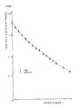
- Figure 5 is a graph showing the rate of change of oscillating frequency with respect to distance in this example.
- Figure 6 is a second circuit diagram of the oscillator circuit in this first embodiment.
- Figure 7 is a third circuit diagram of the oscillator circuit in this first embodiment.
- Figure 8 is a first block diagram of a proximity switch according to the second embodiment based on high frequency oscillation which uses the oscillator circuit described in the first embodiment.
- Figure 9 is a second block diagram showing another high frequency oscillation-type proximity switch of the second embodiment using the oscillator circuit described in the first embodiment.
- A principle which underlies this invention is illustrated in Figure 2 (a) which shows an equivalent circuit for oscillator coil L in the oscillator circuit. Oscillator coil L has inductance L1 and DC resistance ri. When an object approaches the vicinity of the oscillator coil L, the effect of its proximity is a response equivalent to what would occur in the presence of coil L2 and DC resistor r2. Calling the mutual inductance M, the impedance Z as seen from both terminals of the oscillator coil is given by:

- If, for the sake of convenience,
Equation 1 is divided into a real number portion and an imaginary number portion using the symbols Rx and Lx, the two terminals of the coil are indicated equivalently as shown in Figure 2 (b). The invention uses this characteristic in its design so that the change in oscillating frequency of the oscillator circuit is the same regardless of whether the approaching object is made of a magnetic or non-magnetic metal. - Figure 1 (a) is a schematic diagram illustrating the basic structure of this invention. Figure 1 (a) shows a comparator or switching
circuit 1.Reference power supply 2, which supplies voltage Vth, is connected to the non-inverting input terminal of thecomparator 1. The output ofcomparator 1 returns to ground through the series connection of resistor R1 and capacitor C1. The midpoint of this network returns to ground through the series connection of oscillator coil L and capacitor C2. The midpoint between oscillator coil L and capacitor C2 is connected to the inverting input terminal ofcomparator 1. As can be seen in Figure 1 (b), whenobject 3 approaches, oscillator coil L functions just as in Figure 2 (a). The effects on Li, ri ofobject 3 are represented by inductance L2 and resistance r2. This being the case, the effect ofobject 3 is represented as shown in Figure 1 (c), as was discussed above with respect to Figures 2a and 2b. -
Comparator 1 is a switching circuit which outputs a high or low level signal. This can be represented byswitch 4 in the equivalent circuit in Figure 3. - Assume that the terminal of resistor R1 can be connected at the user's discretion to either the ground or a power supply with voltage E, and call the output voltage Vx from what becomes the common connection terminal of resistor Rx and capacitor C2. Vin can then be expressed as follows.
- Calling the charges of capacitors C1 and C2, q1 and q2 respectively, then the following formula will obtained.


- Expressing, this using a Laplace transform element 5, obtains the following: When Vin = E,

WhenV in = 0,
- Using these formulas, the characteristic equation F (S) can be expressed as follows.

- Using this characteristic equation, the oscillating frequency ωose can be expressed by the following formula.

- Thus the oscillating frequency f can be expressed as Formula (9).

- Lx is in the denominator in Formula (9), and Rx is in the numerator. When a magnetic metal approaches, the oscillating frequency will increase because of the increase in Rx; when a non-magnetic metal approaches, the frequency will increase because of the decrease in Lx. By choosing the values of resistor R1 and capacitors C1and C2, or adjusting said values by known adjustment means, we can adjust the ratio of the first and second terms in Formula (6) so that the changing rate of the oscillating frequency is identical for the approach of magnetic and non-magnetic metals.
- Figures 4 (a) and (b) graphically illustrate how resistance Rx and inductance Lx vary with the distance, d, for a magnetic metal (iron) and a non-magnetic metal (aluminum). As can be seen in the graphs, the resistance and inductance both vary as exponential functions, differing only in their coefficients for the different materials. The values of capacitors C1 and C2 and resistor R1 are determined as follows. Capacitors C1 and C2 and corresponding oscillator coil L form the oscillator circuit of the proximity switch. They are selected so as to provide a suitable oscillating frequency. Call the resistance value for iron at a specified distance, di, Rx1 (Fe), and that for aluminum Rx1 (Al). Then call the inductance for iron at the same distance Lx1 (Fe) and that for aluminum Lx1 (Al). A frequency equivalent to the oscillating frequency at this time can be obtained by employing
Formula 10.
- When C1, C2 and R1 are selected so as to satisfy this formula, it can be seen that the oscillating frequencies are equal. When C1 and C2 are determined by the oscillating frequency, the equation can be solved for Ri. This value can then be used as the value of resistor R1. The inductance and resistance in the presence of magnetic and non-magnetic metals are equal at an infinite distance, which will cause the oscillating frequencies associated with them to coincide. The oscillating frequencies at a distance, di, are made to coincide. There are thus two points at which the rates of change of the oscillating frequency corresponding to a change in the distance of the object will coincide. As can be seen in Figure 4, the dependencies of resistance Rx and inductance Lx on distance for the different materials differ only in their coefficients. This is illustrated by the rates of change of the very similarly shaped exponential curves shown in Figures 4a and 4b. Thus the rats of change of the oscillating frequency would virtually coincide for the different materials for any distance beyond d1. This has been confirmed experimentally, and the characteristics shown in Figure 5 have been obtained. In this graph, the rate of change of oscillating frequency is plotted with respect to the distance of a magnetic object (iron), represented by O, and a non-magnetic object (aluminum), represented by X.
- The equation can be solved in the same fashion as Formula (10) for distances other than di, say d2 and d3, and the values for capacitors C1 and C2 and resistor R1 can be determined by simultaneous equations. In this way the characteristics can be made to coincide perfectly. However, this scheme does not allow the user to freely choose an oscillating frequency, which suggests that it would not be appropriate for a proximity switch. For this reason, we have chosen an example in which Formula (10) is established for one specified distance d1. Appropriate values for C1 and C2 are selected, and an oscillating frequency is chosen. The characteristic rates of change of oscillating frequency corresponding to different types of metals are made to be very similar.
- Figure 6 is a second circuit diagram of an oscillator circuit which might be used in the first embodiment. In this example, inverter 11 is used in place of the
comparator 1 in the first example described above. As previously explained resistor R1, capacitor C1, output coil L and capacitor C2, are connected on the output side of inverter 11 replacingcomparator 1, are identical with those described in the first example. It would also be possible in this example to use an inverting amplifier with a high amplification factor in place of inverter 11. The input signal would be discriminated at a specified threshold and the output inverted. Thus the switching signals would be the outputs of the respective switching circuits. - Figure 7 is a third circuit diagram of another oscillator circuit which can be used in the first embodiment. In this example, as can be seen in the diagram, resistor R2 is connected in parallel with capacitor C2. In this case, the oscillating frequency can be obtained from Formula (11) given below.
-

- In Formula (11), the third term of the square root is unrelated to Lx and Rx. As a result, the oscillating frequency f can be adjusted to the desired frequency by choosing an appropriate resistance value for resistor R2. In this case, too, it would be possible to substitute an inverter or inverting amplifier with a high amplification factor for
comparator 1. - Figure 8 is a first block diagram illustrating the structure of one possible proximity switch according to a second embodiment, based on, for example, high frequency oscillation which employs the oscillator circuit described in the first embodiment. The frequency of the oscillator circuit described as the first embodiment herein can be monitored at any convenient point in the circuit. In this switch, the output of
comparator 1 is supplied to resistor R1 and connected to frequency to voltage (F/V)converter circuit 21.Circuit 21 converts the frequency of its input signal to voltage. Its output is transmitted to signal processing circuit 22, which determines the distance of the object according to the graph in Figure 5, which was discussed above. This determination is based on a comparison of the voltage signal when no object is proximate to the voltage when an object is proximate. The output of signal processing circuit 22 is monitored and transmitted for use to an exterior circuit by way ofoutput circuit 23. For circuit 22, a non-linear output circuit could be used; or the distance signals could be stored in a memory, e.g. a ROM table, and then output. - A proximity switch using an oscillator circuit will not have intermittent oscillation, but will produce a signal whose frequency varies continuously in correspondence with the distance at which the object is detected. One could establish the optimal detection range for the distance from the proximity switch to the object and add on a self-diagnostic feature, which would output a warning signal when the object was outside this range.
- Figure 9 is a block diagram illustrating another example of a proximity switch based on high frequency oscillation which employs the oscillator circuit described in the first example. In this switch, the output terminal of
comparator 1 is added to resistor R1 and connected to calculation circuit 31. Circuit 31 calculates the number of pulses associated with the oscillating frequency. Its output is transmitted tocomputation circuit 32, which outputs the distance of the object based on a comparison of the ordinary oscillating frequency with that when an object is proximate. The resulting signal is output for use by an exterior circuit by way of output circuit 33. - As has been explained in detail in the preceding discussion, this invention features an extremely simple configuration which enables it to detect, with identical changing rate of oscillating frequency, both magnetic and non-magnetic metals. Furthermore, the fact that it employs only a single oscillator coil insures that it can be adjusted easily and is capable of achieving a high level of stability.
- This invention does not employ the switching on and off of oscillation at a threshold, as in conventional oscillator circuits. Rather, the frequency varies continuously with the distance of the object to be detected. Thus, one could easily incorporate in the output circuit or add on a self-diagnosing feature to limit the detection zone of the oscillator circuit.
- While several embodiments of the invention have been described, it will be understood that it is capable of further modifications, and this application is intended to cover any variations, uses, or adaptations of the invention, following in general the principles of the invention and including such departures from the present disclosure as to come within knowledge or customary practice in the art to which the invention pertains, and as may be applied to the essential features hereinbefore set forth and falling within the scope of the invention or the limits of the appended claims.
Claims (19)
Applications Claiming Priority (2)
| Application Number | Priority Date | Filing Date | Title |
|---|---|---|---|
| JP3296202A JPH05110412A (en) | 1991-10-15 | 1991-10-15 | Oscillator circuit and high frequency oscillation type proximity switch |
| JP296202/91 | 1991-10-15 |
Publications (2)
| Publication Number | Publication Date |
|---|---|
| EP0537747A2 true EP0537747A2 (en) | 1993-04-21 |
| EP0537747A3 EP0537747A3 (en) | 1993-06-02 |
Family
ID=17830496
Family Applications (1)
| Application Number | Title | Priority Date | Filing Date |
|---|---|---|---|
| EP19920117642 Withdrawn EP0537747A3 (en) | 1991-10-15 | 1992-10-15 | Oscillator circuit and proximity switch using it |
Country Status (3)
| Country | Link |
|---|---|
| US (1) | US5264809A (en) |
| EP (1) | EP0537747A3 (en) |
| JP (1) | JPH05110412A (en) |
Cited By (8)
| Publication number | Priority date | Publication date | Assignee | Title |
|---|---|---|---|---|
| DE19611810A1 (en) * | 1996-03-26 | 1997-10-02 | Balluff Gebhard Gmbh & Co | Non contact inductive proximity switch |
| WO1999014559A1 (en) * | 1997-09-16 | 1999-03-25 | Caterpillar Inc. | An apparatus for determining the position of a work implement |
| DE4427990C2 (en) * | 1994-08-08 | 2000-11-23 | Becker Wolf Juergen | Inductive proximity sensor for material-independent distance measurement |
| WO2004027994A1 (en) * | 2002-09-12 | 2004-04-01 | Cherry Gmbh | Inductive switch |
| DE10004718B4 (en) * | 2000-02-03 | 2006-04-20 | Balluff Gmbh | Inductive proximity sensor |
| US7701201B2 (en) | 2003-09-11 | 2010-04-20 | Cherry Gmbh | Inductive switch |
| US7719263B2 (en) | 2006-11-22 | 2010-05-18 | Zf Friedrichshafen Ag | Inductive position measuring device or goniometer |
| EP2911299A1 (en) * | 2014-02-20 | 2015-08-26 | Pepperl + Fuchs GmbH | Method and circuit for evaluating a physical measurement value measured by a sensor |
Families Citing this family (5)
| Publication number | Priority date | Publication date | Assignee | Title |
|---|---|---|---|---|
| US6446012B1 (en) * | 1999-06-23 | 2002-09-03 | Bfcs Technology, Inc. | Proximity detector for hard-to-detect materials |
| US7667547B2 (en) * | 2007-08-22 | 2010-02-23 | Cardiomems, Inc. | Loosely-coupled oscillator |
| CN103427764B (en) * | 2013-08-29 | 2015-10-14 | 高玉琴 | A kind of oscillator of metal detector |
| DE202020105904U1 (en) | 2020-10-15 | 2021-10-18 | Cherry Europe Gmbh | Device for detecting a key press of a key module and keyboard |
| JP7765962B2 (en) | 2021-12-23 | 2025-11-07 | 東洋エンジニアリング株式会社 | Design support device, design support method and program |
Family Cites Families (4)
| Publication number | Priority date | Publication date | Assignee | Title |
|---|---|---|---|---|
| DE3912946C3 (en) * | 1989-04-20 | 1996-06-20 | Turck Werner Kg | Inductive proximity switch |
| JPH02312316A (en) * | 1989-05-26 | 1990-12-27 | Omron Corp | High frequency oscillation type proximity switch |
| JPH0514749A (en) * | 1991-07-02 | 1993-01-22 | Toshiba Corp | Color copy controller |
| JPH05330672A (en) * | 1992-06-01 | 1993-12-14 | Fuji Electric Co Ltd | Bill delivery device |
-
1991
- 1991-10-15 JP JP3296202A patent/JPH05110412A/en active Pending
-
1992
- 1992-10-14 US US07/959,926 patent/US5264809A/en not_active Expired - Fee Related
- 1992-10-15 EP EP19920117642 patent/EP0537747A3/en not_active Withdrawn
Cited By (12)
| Publication number | Priority date | Publication date | Assignee | Title |
|---|---|---|---|---|
| DE4427990C2 (en) * | 1994-08-08 | 2000-11-23 | Becker Wolf Juergen | Inductive proximity sensor for material-independent distance measurement |
| DE19611810A1 (en) * | 1996-03-26 | 1997-10-02 | Balluff Gebhard Gmbh & Co | Non contact inductive proximity switch |
| DE19611810C2 (en) * | 1996-03-26 | 2000-12-28 | Balluff Gebhard Gmbh & Co | Non-contact proximity switch |
| WO1999014559A1 (en) * | 1997-09-16 | 1999-03-25 | Caterpillar Inc. | An apparatus for determining the position of a work implement |
| DE10004718B4 (en) * | 2000-02-03 | 2006-04-20 | Balluff Gmbh | Inductive proximity sensor |
| DE10004718C5 (en) * | 2000-02-03 | 2008-06-19 | Balluff Gmbh | Inductive proximity sensor |
| WO2004027994A1 (en) * | 2002-09-12 | 2004-04-01 | Cherry Gmbh | Inductive switch |
| US7633026B2 (en) | 2002-09-12 | 2009-12-15 | Zf Friedrichshafen Ag | Inductive switch |
| US7701201B2 (en) | 2003-09-11 | 2010-04-20 | Cherry Gmbh | Inductive switch |
| US7719263B2 (en) | 2006-11-22 | 2010-05-18 | Zf Friedrichshafen Ag | Inductive position measuring device or goniometer |
| EP2911299A1 (en) * | 2014-02-20 | 2015-08-26 | Pepperl + Fuchs GmbH | Method and circuit for evaluating a physical measurement value measured by a sensor |
| US9638651B2 (en) | 2014-02-20 | 2017-05-02 | Pepperl + Fuchs Gmbh | Method and circuit for evaluating a physical quantity detected by a sensor |
Also Published As
| Publication number | Publication date |
|---|---|
| US5264809A (en) | 1993-11-23 |
| EP0537747A3 (en) | 1993-06-02 |
| JPH05110412A (en) | 1993-04-30 |
Similar Documents
| Publication | Publication Date | Title |
|---|---|---|
| US5264809A (en) | Oscillator circuit and proximity switch using | |
| US4678992A (en) | Electronic metal detector | |
| US3973191A (en) | Inductive displacement sensor apparatus | |
| US5012206A (en) | Inductive proximity switch | |
| US6031430A (en) | Temperature stabilized oscillator and proximity switch containing the oscillator | |
| EP0336615B1 (en) | Electromagnetic flowmeter capable of simultaneous measurement of flow rate and conductivity of fluid | |
| US4068189A (en) | Linear oscillator for proximity sensor | |
| EP0237171B1 (en) | Inductance divider sensor | |
| AU662739B2 (en) | Vehicle detector with series resonant oscillator drive | |
| US4509023A (en) | Oscillator with a temperature compensated oscillating coil | |
| EP0305013A2 (en) | Inductive proximity sensor | |
| EP0608966A2 (en) | Adjustable reactance device and method | |
| US9479165B2 (en) | Inductive proximity switch and method for its operation | |
| US6335619B1 (en) | Inductive proximity sensor comprising a resonant oscillatory circuit responding to changes in inductive reaction | |
| JPH02312316A (en) | High frequency oscillation type proximity switch | |
| DE19538575C2 (en) | Inductive proximity sensor | |
| DE19817722C2 (en) | Method and arrangement for evaluating the admittance of a variable measuring capacity | |
| US4075551A (en) | Inductive displacement sensor | |
| US6078172A (en) | Current-compensated current sensor for hysteresis-independent and temperature-independent current measurement | |
| US2918666A (en) | Condition responsive electrical system | |
| EP1671159B1 (en) | Method and apparatus for metal target proximity detection at long distances | |
| GB2137360A (en) | Electromagnetic flowmeter | |
| US2755446A (en) | Variable inductance control method and apparatus | |
| US3444738A (en) | Self-oscillating impedance measuring loop | |
| WO2008022231A2 (en) | Magnetic toroid self resonant current sensor |
Legal Events
| Date | Code | Title | Description |
|---|---|---|---|
| PUAI | Public reference made under article 153(3) epc to a published international application that has entered the european phase |
Free format text: ORIGINAL CODE: 0009012 |
|
| PUAL | Search report despatched |
Free format text: ORIGINAL CODE: 0009013 |
|
| 17P | Request for examination filed |
Effective date: 19921112 |
|
| AK | Designated contracting states |
Kind code of ref document: A2 Designated state(s): DE ES FR GB IT |
|
| AK | Designated contracting states |
Kind code of ref document: A3 Designated state(s): DE ES FR GB IT |
|
| 17Q | First examination report despatched |
Effective date: 19951215 |
|
| STAA | Information on the status of an ep patent application or granted ep patent |
Free format text: STATUS: THE APPLICATION IS DEEMED TO BE WITHDRAWN |
|
| 18D | Application deemed to be withdrawn |
Effective date: 19960626 |