EP0537337B1 - Mikrowellenkamera - Google Patents
Mikrowellenkamera Download PDFInfo
- Publication number
- EP0537337B1 EP0537337B1 EP92913281A EP92913281A EP0537337B1 EP 0537337 B1 EP0537337 B1 EP 0537337B1 EP 92913281 A EP92913281 A EP 92913281A EP 92913281 A EP92913281 A EP 92913281A EP 0537337 B1 EP0537337 B1 EP 0537337B1
- Authority
- EP
- European Patent Office
- Prior art keywords
- antenna
- frequency
- laser
- view
- field
- Prior art date
- Legal status (The legal status is an assumption and is not a legal conclusion. Google has not performed a legal analysis and makes no representation as to the accuracy of the status listed.)
- Expired - Lifetime
Links
- 230000005855 radiation Effects 0.000 claims description 51
- 238000001228 spectrum Methods 0.000 claims description 14
- 238000003384 imaging method Methods 0.000 claims description 12
- 230000005540 biological transmission Effects 0.000 claims description 11
- 238000001514 detection method Methods 0.000 claims description 10
- 238000004458 analytical method Methods 0.000 claims description 7
- 238000006243 chemical reaction Methods 0.000 claims description 7
- 230000001419 dependent effect Effects 0.000 claims description 4
- 239000003086 colorant Substances 0.000 claims description 2
- 229910052782 aluminium Inorganic materials 0.000 description 7
- XAGFODPZIPBFFR-UHFFFAOYSA-N aluminium Chemical compound [Al] XAGFODPZIPBFFR-UHFFFAOYSA-N 0.000 description 7
- 239000011120 plywood Substances 0.000 description 7
- 239000011888 foil Substances 0.000 description 6
- 229910005540 GaP Inorganic materials 0.000 description 4
- 239000005030 aluminium foil Substances 0.000 description 3
- 238000010586 diagram Methods 0.000 description 3
- HZXMRANICFIONG-UHFFFAOYSA-N gallium phosphide Chemical compound [Ga]#P HZXMRANICFIONG-UHFFFAOYSA-N 0.000 description 3
- 230000005457 Black-body radiation Effects 0.000 description 1
- 230000005670 electromagnetic radiation Effects 0.000 description 1
- 238000000034 method Methods 0.000 description 1
- 238000012544 monitoring process Methods 0.000 description 1
- 230000010363 phase shift Effects 0.000 description 1
- 238000002310 reflectometry Methods 0.000 description 1
- 230000001105 regulatory effect Effects 0.000 description 1
- XLYOFNOQVPJJNP-UHFFFAOYSA-N water Substances O XLYOFNOQVPJJNP-UHFFFAOYSA-N 0.000 description 1
Images


Classifications
-
- H—ELECTRICITY
- H01—ELECTRIC ELEMENTS
- H01Q—ANTENNAS, i.e. RADIO AERIALS
- H01Q19/00—Combinations of primary active antenna elements and units with secondary devices, e.g. with quasi-optical devices, for giving the antenna a desired directional characteristic
- H01Q19/10—Combinations of primary active antenna elements and units with secondary devices, e.g. with quasi-optical devices, for giving the antenna a desired directional characteristic using reflecting surfaces
- H01Q19/12—Combinations of primary active antenna elements and units with secondary devices, e.g. with quasi-optical devices, for giving the antenna a desired directional characteristic using reflecting surfaces wherein the surfaces are concave
- H01Q19/17—Combinations of primary active antenna elements and units with secondary devices, e.g. with quasi-optical devices, for giving the antenna a desired directional characteristic using reflecting surfaces wherein the surfaces are concave the primary radiating source comprising two or more radiating elements
- H01Q19/175—Combinations of primary active antenna elements and units with secondary devices, e.g. with quasi-optical devices, for giving the antenna a desired directional characteristic using reflecting surfaces wherein the surfaces are concave the primary radiating source comprising two or more radiating elements arrayed along the focal line of a cylindrical focusing surface
-
- G—PHYSICS
- G01—MEASURING; TESTING
- G01R—MEASURING ELECTRIC VARIABLES; MEASURING MAGNETIC VARIABLES
- G01R29/00—Arrangements for measuring or indicating electric quantities not covered by groups G01R19/00 - G01R27/00
- G01R29/08—Measuring electromagnetic field characteristics
- G01R29/0864—Measuring electromagnetic field characteristics characterised by constructional or functional features
- G01R29/0892—Details related to signal analysis or treatment; presenting results, e.g. displays; measuring specific signal features other than field strength, e.g. polarisation, field modes, phase, envelope, maximum value
-
- G—PHYSICS
- G01—MEASURING; TESTING
- G01S—RADIO DIRECTION-FINDING; RADIO NAVIGATION; DETERMINING DISTANCE OR VELOCITY BY USE OF RADIO WAVES; LOCATING OR PRESENCE-DETECTING BY USE OF THE REFLECTION OR RERADIATION OF RADIO WAVES; ANALOGOUS ARRANGEMENTS USING OTHER WAVES
- G01S17/00—Systems using the reflection or reradiation of electromagnetic waves other than radio waves, e.g. lidar systems
- G01S17/02—Systems using the reflection of electromagnetic waves other than radio waves
- G01S17/50—Systems of measurement based on relative movement of target
- G01S17/58—Velocity or trajectory determination systems; Sense-of-movement determination systems
-
- G—PHYSICS
- G01—MEASURING; TESTING
- G01S—RADIO DIRECTION-FINDING; RADIO NAVIGATION; DETERMINING DISTANCE OR VELOCITY BY USE OF RADIO WAVES; LOCATING OR PRESENCE-DETECTING BY USE OF THE REFLECTION OR RERADIATION OF RADIO WAVES; ANALOGOUS ARRANGEMENTS USING OTHER WAVES
- G01S17/00—Systems using the reflection or reradiation of electromagnetic waves other than radio waves, e.g. lidar systems
- G01S17/88—Lidar systems specially adapted for specific applications
- G01S17/95—Lidar systems specially adapted for specific applications for meteorological use
-
- G—PHYSICS
- G01—MEASURING; TESTING
- G01S—RADIO DIRECTION-FINDING; RADIO NAVIGATION; DETERMINING DISTANCE OR VELOCITY BY USE OF RADIO WAVES; LOCATING OR PRESENCE-DETECTING BY USE OF THE REFLECTION OR RERADIATION OF RADIO WAVES; ANALOGOUS ARRANGEMENTS USING OTHER WAVES
- G01S7/00—Details of systems according to groups G01S13/00, G01S15/00, G01S17/00
- G01S7/48—Details of systems according to groups G01S13/00, G01S15/00, G01S17/00 of systems according to group G01S17/00
- G01S7/483—Details of pulse systems
- G01S7/486—Receivers
-
- G—PHYSICS
- G02—OPTICS
- G02F—OPTICAL DEVICES OR ARRANGEMENTS FOR THE CONTROL OF LIGHT BY MODIFICATION OF THE OPTICAL PROPERTIES OF THE MEDIA OF THE ELEMENTS INVOLVED THEREIN; NON-LINEAR OPTICS; FREQUENCY-CHANGING OF LIGHT; OPTICAL LOGIC ELEMENTS; OPTICAL ANALOGUE/DIGITAL CONVERTERS
- G02F1/00—Devices or arrangements for the control of the intensity, colour, phase, polarisation or direction of light arriving from an independent light source, e.g. switching, gating or modulating; Non-linear optics
- G02F1/01—Devices or arrangements for the control of the intensity, colour, phase, polarisation or direction of light arriving from an independent light source, e.g. switching, gating or modulating; Non-linear optics for the control of the intensity, phase, polarisation or colour
- G02F1/09—Devices or arrangements for the control of the intensity, colour, phase, polarisation or direction of light arriving from an independent light source, e.g. switching, gating or modulating; Non-linear optics for the control of the intensity, phase, polarisation or colour based on magneto-optical elements, e.g. exhibiting Faraday effect
-
- Y—GENERAL TAGGING OF NEW TECHNOLOGICAL DEVELOPMENTS; GENERAL TAGGING OF CROSS-SECTIONAL TECHNOLOGIES SPANNING OVER SEVERAL SECTIONS OF THE IPC; TECHNICAL SUBJECTS COVERED BY FORMER USPC CROSS-REFERENCE ART COLLECTIONS [XRACs] AND DIGESTS
- Y02—TECHNOLOGIES OR APPLICATIONS FOR MITIGATION OR ADAPTATION AGAINST CLIMATE CHANGE
- Y02A—TECHNOLOGIES FOR ADAPTATION TO CLIMATE CHANGE
- Y02A90/00—Technologies having an indirect contribution to adaptation to climate change
- Y02A90/10—Information and communication technologies [ICT] supporting adaptation to climate change, e.g. for weather forecasting or climate simulation
Definitions
- This invention is related to cameras and in particular to microwave cameras.
- the emitted power is proportional to ⁇ T for the body and is typically not a function of frequency.
- most bodies to some extent reflect microwave radiation from the surroundings and some bodies which are transparent will transmit energy from objects behind it.
- the radiometric temperature of a body is defined as being equal to the thermometric temperatures of an ideal black body that would give the same radiation as that emanating from the body.
- T (1-r-t) T 1 + r T 2 + ⁇ T 3
- T 1 For water ⁇ is close to 1, for metallic objects r is close to 1, and for many natural objects t is close to one.
- T 2 representing the temperature of the sky will be in the range of a few degrees K (say 10°K).
- T B T A ⁇ 300 10 ⁇ 30
- microwave radiation emanating from the non-reflecting background should be about a factor of up to about 30 greater than the emanating from aluminium foil reflecting the sky.
- a microwave camera system for imaging objects within a field-of-view comprising:
- a camera system comprising:
- microwave radiation is intended to cover electromagnetic radiation within a frequency range of about 10 9 Hz to about 10 12 Hz.
- FIGS. 1A, 1B, 2A, 2B and 3 A prototype demonstration unit is described in FIGS. 1A, 1B, 2A, 2B and 3.
- a one meter long microwave antenna 2 is mounted at the focus of a parabolic reflector 4 which is mounted on a table 5 rotatable around the focus of reflector 4.
- Parabolic reflector 4 limits the horizontal field-of-view of microwave antenna 2 to about 1 degree.
- Cut in the face (side 6) of antenna 2 are 112 slots for collecting microwave radiation. The spacing of these slots are chosen to permit the antenna to detect microwave radiation in the range of approximately 17-21 GHz.
- the slots are described in Table 1.
- FIG. 3 is a block diagram showing in detail the equipment used to construct this preferred embodiment of the present invention.
- the waveguide antenna used was constructed of type WR51 waveguide and supplied by Vantage Corporation of San Diego, California. Output from the antenna goes to coax adapter 22 which is connected by coax cable to low noise amplifier 8 made by MITEQ Corporation which provides a 15 dB gain for frequencies within the 17-21 GHz range.
- the output from amplifier 8 goes to mixer 24 where it is mixed with the output of variable frequency generator 26.
- Frequency generator 26 is controlled by D/A converter 28 which is regulated by computer 30.
- Computer 30 is programmed to cause frequency generator 26 to produce frequencies varying from 13 to 17 GHz.
- the output of mixer 24 goes to bandpass filter 32 (supplied by Trilithic Corporation) which is designed to pass only approximately 4 GHz signals. (Frequencies passed are between 3.75, and 4.25 GHz.)
- the Bragg cell used in this prototype is a Gallium Phosphide (GaP) cell supplied by Brimrose Corporation, Baltimore MD.
- the cell has a center frequency of 1.2 GHz and a bandwidth of 500 MHz. (i.e., an operation range of 1.2 ⁇ 0.25 GHz.)
- the Bragg angle is 3.8 degrees for 700 nm and the defraction efficiency at .8 Watt is 60%.
- the 1.2 ⁇ 0.25 GHz signal sets up an interference pattern in Bragg cell 34 which diffracts laser beam 10 from laser 12.
- Pixel array 16 of video camera 18 is appropriately positioned to detect the diffracted portion of beam 10 (at 700 nm). (The undiffracted portion of the beam passes and does not illuminate pixel array 16.)
- the spacing between the slots on antenna 2 are .344 inches (.874 cm). This corresponds to 1/2 wavelength of 20.7 GHz microwave radiation within antenna 2.
- the signal from the antenna is mixed with mixing signal at about 16.7 GHz which produces a difference signal of about 4 GHz which is filtered through filter 32 which blocks all frequencies not in the range of about 4 ⁇ 0.25 GHz.
- the signal passing through filter 32 is amplified convened and mixed again to 1.2 ⁇ 0.25 GHz.
- T his 1.2 ⁇ 0.25 GHz signal is amplified and the amplified signal drives Bragg cell 34.
- frequency generator 26 is producing approximately 16.7 GHz
- the only microwave energy producing modulation in Bragg cell 34 is microwave energy in the range of about 20.7 GHz.
- Antenna 4 will collect 20.7 GHz microwave energy only if it is entering the antenna broadside (i.e at approximately 0 degrees [horizontal] as shown in FIG. 4).
- a mixing signal of 14 GHz is provided by frequency generator 26 to produce a difference signal in the range of about 4 ⁇ 0.25 GHz which passes bandpass filter 32, is amplified and modulates Bragg cell 34.
- Bragg cell 32 is now being modulated by approximately 18 GHz microwave radiation source located about 10.81 degrees below the horizon.
- microwave frequencies between 17 GHz, and 21 GHz can be made to modulate Bragg cell 34 by providing mixing frequencies of 13 to 17 GHz provided the signals originate at the appropriate elevation on the vertical axis as shown in FIG. 4.
- this device as a microwave camera is based on the assumption that objects of interest will produce microwave radiation more or less uniformly as a function of frequency over its surface area of interest in the range of 17 GHz to 21 GHz.
- the antenna can be made to "look" in any vertical direction between -16.09 degrees and +1 degrees by merely varying the mixing frequency produced by generator 26 between 13 GHz and 17 GHz.
- the bandpass of filter 32 is 4 ⁇ 0.25 GHz as stated above. This ⁇ 0.25 GHz range corresponds to a vertical angle of about 2 degrees.
- the frequency generator controls to produce eight equally spaced frequencies between 13 GHz and 17 GHz, which meant that our vertical field-of-view was described by eight 2.125 degrees vertical slices between -16 degrees and + 1 degrees.
- Parabolic mirror 4 limited the horizontal field-of-view to 1 degree. Therefore our instantaneous field-of-view was about 1 degree wide. We were able to scan in the horizontal direction by rotating mirror 4 about its center of focus. For our demonstration, to take a microwave picture of the target shown in FIG. 5, we provided 30 equally spaced horizontal settings of 1 degree each for a total horizontal field-of-view of 30 degrees. Thus, we were able to create a total field-of-view of 30 degrees horizontal and 17 degrees vertical. To produce a "television" picture of our target area we scanned vertically for each horizontal setting and displayed the output incrementally on computer display 44.
- FIG. 6 of the view shown in the photograph reproduced as FIG. 5.
- the TE in FIG. 5 was made of one foot wide strips of aluminum foil mounted on plywood and the plywood was tilted so the aluminum foil reflected the cold sky.
- the TE shows up as dark spots on FIG. 6.
- the microwave radiation emanating from the aluminum is very low since the emissions are low, since it is largely opaque to microwave radiation and since it is reflecting microwave radiation from the cold sky.
- the microwaves radiation from the plywood is high since its emissions are higher and since it is also fairly transparent to microwave radiation from the landscape behind it.
- FIGS. 1A, 1B, 2A and 2B can be used to provide acousto-optic imaging in one dimension.
- the antenna system shown in FIG. 1A, 1B, 2A and 2B has a beam direction-frequency relation shown in FIG. 7A.
- the Brimrose Corporation gallium phosphide Bragg cell 34 depicted in FIG. 1B and described above has a laser beam diffraction-Bragg cell frequency relationship as shown in FIG. 7B.
- a frequency of 14 GHz is output from VCO 26 and mixed with the antenna output, handpass filtered 32, and then downconverted to 1.2 GHz by C-band low noise block downconverter 36, and the net result fed to Bragg Cell 34.
- the direction of laser beam 10 from laser 12 will be diffracted by microwave radiation from sources which are located within the vertical field-of-view between about 9° and 11° below the antenna broadside as shown on FIG. 7.
- a point (or horizontal line) broad band microwave source located at 11° would cause a diffraction pattern in Bragg cell 34 to be set up which would diffract laser beam 10 about 5.5°.
- a point (or horizontal line) broad band source located at 9° would cause a separate pattern to be set up which would diffract the beam about 8.2°. Both (in fact many) diffraction patterns can exist in the Bragg cell at the same time.
- FIG. 11 shows up as two horizontal lines on monitor 44 corresponding to a 5.5° and an 8.2° diffraction of laser beam 10.
- This system thus produces a real time one dimensional image of the two point (or line) microwave scene.
- Figure 8 combines the information in FIGS. 7A and 7B. The results of a demonstration proving this principal is shown in FIG. 11.
- the lower part of FIG. 9 shows 7 targets located about 50 feet from antenna 2.
- the targets consisted of 1 foot wide strips of aluminum foil placed horizontally on a plywood background. The target was tilted so that the sky would be reflected from the foil to the antenna.
- the strip positions were low, center and top.
- the one dimensional real time images of center portions of these 7 targets are shown directly above each of the targets at the top of FIG. 11.
- the aluminum foil strips appear as dark thick strips on a white background.
- the prototype produces a one dimensional real time image of a field-of-view which is about 1° in the horizontal and 2° in the vertical.
- a two dimensional essentially real time image could be provided by rotating the antenna or monitoring the antenna on a moving vehicle and displaying sequential vertical images side-by-side on the monitor.
- the antenna is rotated at 1° per second and a new image is displayed and stored each second respectively on a 4 inch by 1 inch adjacent sections of the monitor, at the end of 10 seconds, we would have a 4 inch by 10 inch image of a 2° vertical by 10° horizontal field-of-view.
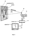
- any microwave antenna system 50 providing a beam which can be frequency scanned can be utilized in the practice of this invention.
- any of many available spectrum analyzers 54 capable of analyzing the spectrum of the radiation being received by antenna 54 can be used.
- Frequency scannable antenna types which are available include the following:
- antenna 50 which could be any of the antenna listed above, collects microwaves from target 52 which in this example is made of aluminum foil letters TE on a plywood background. The target is tilted backward so that the TE will reflect the cold sky. Output from the antenna is analyzed by spectrum analyzer 54. The output of analyzer 54 is utilized by computer 56 to create an image which may be displayed on monitor 58. In this case the figure shows a vertical instantaneous field-of-view of a section of an E in target 52. The output analysis of spectrum analyzer, for the single vertical strips is depicted in FIG. 12. As indicated on FIG. 12 the radiation from the aluminum portions of the target are substantially lower than from the plywood and show up as three negative blips. As indicated in FIG.
- 11 computer 56 correlates the negative blips with the frequency being detected and plots an appropriate output on monitor 58 at the appropriate vertical and horizontal direction.
- a one dimensional image is produced by creating on monitor 58 spots of varying brightness based on the amplitude of the spectrum analyses and vertical positioning of such spots is determined by the frequency. Horizontal positioning is based on the direction of the antenna beam. Spots can also be created of various colors instead of brightness in order to demonstrate intensity.
- Scanning can also be accomplished by moving antenna 50 in a direction parallel to the area being imaged or by moving target 52 across the narrow vertical beam of antenna 50.
- FIG. 10 An embodiment of the present invention providing a real time two dimensional image is shown in FIG. 10.
- an array of 32 antennae are utilized.
- the signal from each of these antennae are processed as described above with respect to the single antenna system and the resulting signals are fed into a multi-channel (i.e., 32 channels) Bragg cell such as a 32 channel model M GPD-80-50 gallium phosphide cell supplied by Brimrose Corp. of Baltimore Maryland.
- Horizontal spatial resolution is produced as described above under the section entitled acousto-optic one-dimensional imaging. Horizontal spatial resolution is produced as qualitatively described in FIGS. 13A, 13B and 13C.
- Microwave source S is located 100 meters from, and on the right side of the field-of-view of antenna array 60 which is 10 meters wide. Radiation from source S has to travel 0.5 m further to reach the left side of array 60 as compared to the right side. This means that a wavefront from source S arrives on the left side of antenna array 60 about 0.17 x 10 -8 seconds after the arrival on the right side of the same wavefront.
- This 0.17 x 10 -8 second delay results in a phase shift in the Bragg cell of1.2 x 10 9 cyc/sec acoustic waves or about two wavelengths between the left and right sides of the aperture of the cell.
Landscapes
- Physics & Mathematics (AREA)
- Engineering & Computer Science (AREA)
- General Physics & Mathematics (AREA)
- Electromagnetism (AREA)
- Remote Sensing (AREA)
- Radar, Positioning & Navigation (AREA)
- Computer Networks & Wireless Communication (AREA)
- Nonlinear Science (AREA)
- Power Engineering (AREA)
- Optics & Photonics (AREA)
- Radar Systems Or Details Thereof (AREA)
- Variable-Direction Aerials And Aerial Arrays (AREA)
- Ultra Sonic Daignosis Equipment (AREA)
Claims (23)
- Ein Mikrowellenkamera-System zur Abbildung von Objekten innerhalb eines Sichtfeldes, wobei das Kamerasystem besteht aus:einem Antennenelement (2) mit einer frequenzabhängigen Strahlrichtung zur Erfassung von Mikrowellenstrahlung;einem Spektrumanalysator (54) zur Erstellung einer Analyse des Spektrums von zumindest einem Teil der besagten erfassten Strahlung;einem Abbildungselement (44) zur Erstellung eines Abbildes besagter Objekte auf der Grundlage der besagten Analyse; undeinem Frequenzabtastgerät; gekennzeichnet durch:den Spektrumanalysator (54), bestehend aus einer Braggschen Zelle (34) und einem Laser (12); unddem Frequenzabtastgerät, das Frequenzen erzeugt und auswählt, die ein Sichtfeld parallel zu einer ersten Richtung darstellen, wobei die Antenne so angeordnet ist, dass die Strahlrichtung in einer zweiten Richtung orthogonal zur ersten Richtung abgetastet werden kann.
- Das System nach Anspruch 1, in dem die vom besagten Spektrumanalysator (34) erstellte Analyse-ein Signal ist, das die Amplitude eines Teils der besagten erfassten Mikrowellenstrahlung in Abhängigkeit von der Frequenz der besagten Mikrowellenstrahlung darstellt.
- Das System nach Anspruch 2, in dem das besagte Abbildungselement (44) einen Rechner und einen Monitor umfasst und in dem der besagte Rechner ein Abbild auf dem besagten Monitor erzeugt, indem er Punkte auf der Grundlage besagter Amplitude auf besagtem Monitor erscheinen lässt, wobei die Position besagter Punkte auf der besagten Frequenz basiert.
- Das System nach Anspruch 3, in dem besagte Punkte von unterschiedlicher Helligkeit sind.
- Ein System nach Anspruch 3, in dem besagte Punkte von unterschiedlicher Farbe sind.
- Das System nach Anspruch 1, in dem das besagte Abbildungselement (44) eine Fernsehkamera beinhaltet.
- Das System nach Anspruch 1, in dem das besagte Antennenelement (2) eine Vielzahl von Antennen und in dem die besagte Braggsche Zelle (34) eine Vielzahl von Kanälen umfasst.
- Das System nach Anspruch 7, in dem jede der besagten Vielzahl von Antennen an einen separaten Kanal der besagten Vielzahl von Kanälen angeschlossen ist.
- Das System nach Anspruch 8, in dem das besagte Abbildungselement (44) zweidimensionale Abbilder erzeugt.
- Ein Kamerasystem, bestehend aus:einem Antennenelement (2) zur Erkennung von Mikrowellenstrahlungen aus Quellen innerhalb eines Sichtfeldes;einem Frequenzabtastgerät zur Erzeugung und Auswahl von Frequenzen;einem Laser (12) zur Hervorbringung eines Laserstrahls;einem akusto-optischen Laserbeugungselement, bestehend aus einer Braggschen Zelle (34), zur Beugung eines Laserstrahls, welcher von dem besagten Laser hervorgebracht wird;einem Abbildungselement mit einem ersten Umsetzungselement zur Erzeugung eines elektronischen Signals, das zumindest einem Teil der besagten Strahlung, die vom besagten Erkennungselement erkannt wird, entspricht;einem zweiten Umsetzungselement zur Umsetzung des besagten elektronischen Signals in ein akustisches Signal, das sich zur Ansteuerung des besagten akusto-optischen Laserbeugungselementes eignet; undeinem Lichterkennungselement (30) zur Erkennung eines Teils des besagten Laserstrahls, der durch das besagte akusto-optische Beugungselement (34) gebeugt wird;wobei besagte Antenne (2), besagter Laser (12), besagtes Beugungselement (34), besagtes erstes und zweites Umsetzungselement und besagtes Lichterkennungselement (30) so angeordnet sind, dass das von besagtem Lichterkennungselement (30) erkannte Laserlicht der Mikrowellenstrahlung entspricht, die von Objekten, welche innerhalb des besagten Sichtfeldes positioniert sind, ausgeht; gekennzeichnet durch:das Frequenzabtastgerät, welches Frequenzen erzeugt und auswählt, die ein zu einer ersten Richtung paralleles Sichtfeld darstellen; unddie Antenne (2), die eine solche frequenzabhängige Strahlrichtung aufweist, dass die Strahlrichtung in einer zweiten Richtung orthogonal zur ersten Richtung abgetastet werden kann.
- Das System nach Anspruch 10, in dem das besagte Frequenzabtastgerät einen variablen Frequenzgenerator zur Erzeugung variabler Frequenzen beinhaltet, welche mit dem Ausgang des besagten ersten Umsetzungselementes gemischt werden.
- Das System nach Anspruch 10, in dem die Antenne (2) eine Wellenleiterantenne mit Schlitzen ist.
- Das System nach Anspruch 1 oder Anspruch 10, in dem die Antenne (2) eine oder mehrere der folgenden Einrichtungen beinhaltet:eine spiralförmige Übertragungsleitung mit Abgriffen;eine dielektrische Stabübertragungsleitung mit Abgriffen;eine koaxiale Übertragungsleitung mit Abgriffen;ein Übertragungsgitter;ein Reflexionsgitter;ein Dispersionsprisma;eine Parallelplatten-Übertragungsleitung mit Schlitzen;eine dielektrische Schlitzübertragungsleitung mit Abgriffen;eine Streifenleitung mit Abgriffen;einen Mikrostreifenleiter mit Abgriffen; undeine mit Koaxialverzögerungsleitungen verbundene Einzelantenne.
- Das System nach Anspruch 10, in dem die besagte Antenne (2) eine Vielzahl einzelner Erkennungselemente ist, die in einer Matrix angeordnet und so zusammengeschaltet sind, dass sie eine Abbilddefinition in der nicht abgetasteten Richtung liefern.
- Das System nach Anspruch 14, in dem die besagte Matrix eine einheitliche Matrix ist.
- Das System nach Anspruch 14, in dem die besagte Matrix eine dünne Matrix ist.
- Das System nach Anspruch 14, das weiterhin ein elektronisches Steuerungsmittel wie z. B. Phasenschieber oder Dioden beinhaltet, um eine Abbilddefinition in der nicht abgetasteten Richtung zu liefern.
- Das System nach Anspruch 10, das weiterhin eine Mikrowellen-Strahlungsquelle zur Beleuchtung des besagten Sichtfeldes beinhaltet.
- Das System nach Anspruch 10, in dem das besagte Antennenelement (2) eine Vielzahl von Antennen und in dem das akusto-optische Laserbeugungselement (34) eine Vielzahl von Kanälen beinhaltet.
- Das System nach Anspruch 19, in dem jede der besagten Vielzahl von Antennen mit einem separaten Kanal des besagten Beugungselementes verbunden ist.
- Das System nach Anspruch 20, in dem das besagte Lichterkennungselement (30) eine zweidimensionale Matrix aus Lichtdetektoren beinhaltet, um die Erzeugung eines zweidimensionalen Abbildes der Mikrowellenquellen innerhalb des besagten Sichtfeldes auf der Grundlage des Beugungsgrades des besagten Laserstrahls durch das besagte Beugungselement (34) zu ermöglichen.
- Das System nach Anspruch 1, in dem das besagte Frequenzabtastelement einen Frequenzgenerator und einen Mischer beinhaltet, derart, dass besagter Frequenzgenerator und besagter Mischer die Frequenzen im Sichtfeld der ersten Dimension herabsetzen.
- Das System nach Anspruch 1, in dem das besagte Antennenelement einen Spiegel beinhaltet, derart, dass die Strahlrichtung für das besagte Antennenelement im Sichtfeld der zweiten Dimension durch Drehen des besagten Spiegels um seinen Brennpunkt herum abgetastet werden kann.
Applications Claiming Priority (3)
| Application Number | Priority Date | Filing Date | Title |
|---|---|---|---|
| US694098 | 1991-05-01 | ||
| US07/694,098 US5121124A (en) | 1991-05-01 | 1991-05-01 | Microwave camera |
| PCT/US1992/003488 WO1992019986A1 (en) | 1991-05-01 | 1992-04-27 | Microwave camera |
Publications (3)
| Publication Number | Publication Date |
|---|---|
| EP0537337A1 EP0537337A1 (de) | 1993-04-21 |
| EP0537337A4 EP0537337A4 (en) | 1995-06-07 |
| EP0537337B1 true EP0537337B1 (de) | 2002-01-02 |
Family
ID=24787391
Family Applications (1)
| Application Number | Title | Priority Date | Filing Date |
|---|---|---|---|
| EP92913281A Expired - Lifetime EP0537337B1 (de) | 1991-05-01 | 1992-04-27 | Mikrowellenkamera |
Country Status (5)
| Country | Link |
|---|---|
| US (1) | US5121124A (de) |
| EP (1) | EP0537337B1 (de) |
| JP (2) | JP3090685B2 (de) |
| DE (1) | DE69232325T2 (de) |
| WO (1) | WO1992019986A1 (de) |
Families Citing this family (40)
| Publication number | Priority date | Publication date | Assignee | Title |
|---|---|---|---|---|
| US5751243A (en) * | 1990-10-29 | 1998-05-12 | Essex Corporation | Image synthesis using time sequential holography |
| US5248977A (en) * | 1992-05-26 | 1993-09-28 | Trw Inc. | One-dimensional electronic image scanner |
| US5465142A (en) * | 1993-04-30 | 1995-11-07 | Northrop Grumman Corporation | Obstacle avoidance system for helicopters and other aircraft |
| US5365237A (en) * | 1993-05-13 | 1994-11-15 | Thermo Trex Corporation | Microwave camera |
| US5481183A (en) * | 1993-05-13 | 1996-01-02 | Johnson; Paul A. | Electro-optic spectrum analyzer |
| US5815113A (en) * | 1996-08-13 | 1998-09-29 | Trw Inc. | Monolithic, low-noise, synchronous direct detection receiver for passive microwave/millimeter-wave radiometric imaging systems |
| US6037908A (en) * | 1996-11-26 | 2000-03-14 | Thermotrex Corporation | Microwave antenna |
| US5886664A (en) * | 1997-04-16 | 1999-03-23 | Trw Inc. | Method and apparatus for detecting mines using radiometry |
| US7019682B1 (en) * | 2005-04-12 | 2006-03-28 | Trex Enterprises Corp. | Imaging millimeter wave radar system |
| IL172803A0 (en) * | 2005-12-25 | 2007-03-08 | Rafael Advanced Defense Sys | Millimeter wave imaging system |
| GB0617586D0 (en) * | 2006-09-07 | 2006-10-18 | Mbda Uk Ltd | Improvements in or relating to scanners |
| DE102008011350A1 (de) * | 2008-02-27 | 2009-09-03 | Loeffler Technology Gmbh | Vorrichtung und Verfahren zur Echtzeiterfassung von elektromagnetischer THz-Strahlung |
| JP5222092B2 (ja) * | 2008-10-27 | 2013-06-26 | スタンレー電気株式会社 | 人体検知装置 |
| US8237604B2 (en) * | 2009-03-06 | 2012-08-07 | Tialinx, Inc. | Virtual beam forming in ultra wideband systems |
| US8263939B2 (en) * | 2009-04-21 | 2012-09-11 | The Boeing Company | Compressive millimeter wave imaging |
| US8912944B2 (en) * | 2011-03-11 | 2014-12-16 | Thomas W. Gow | Human presence detector suitable for concealment and using a shaped microwave beam |
| EP2847823A2 (de) * | 2012-05-09 | 2015-03-18 | Duke University | Kopplungsvorrichtungen und verfahren zur verwendung davon |
| US9411042B2 (en) | 2012-05-09 | 2016-08-09 | Duke University | Multi-sensor compressive imaging |
| US9575560B2 (en) | 2014-06-03 | 2017-02-21 | Google Inc. | Radar-based gesture-recognition through a wearable device |
| US9811164B2 (en) | 2014-08-07 | 2017-11-07 | Google Inc. | Radar-based gesture sensing and data transmission |
| US9778749B2 (en) | 2014-08-22 | 2017-10-03 | Google Inc. | Occluded gesture recognition |
| US11169988B2 (en) | 2014-08-22 | 2021-11-09 | Google Llc | Radar recognition-aided search |
| US9600080B2 (en) | 2014-10-02 | 2017-03-21 | Google Inc. | Non-line-of-sight radar-based gesture recognition |
| US10016162B1 (en) | 2015-03-23 | 2018-07-10 | Google Llc | In-ear health monitoring |
| US9848780B1 (en) | 2015-04-08 | 2017-12-26 | Google Inc. | Assessing cardiovascular function using an optical sensor |
| CN107430443B (zh) | 2015-04-30 | 2020-07-10 | 谷歌有限责任公司 | 基于宽场雷达的手势识别 |
| EP3885882A1 (de) | 2015-04-30 | 2021-09-29 | Google LLC | Hf-basierte mikrobewegungsverfolgung für gestenverfolgung und -erkennung |
| JP6517356B2 (ja) | 2015-04-30 | 2019-05-22 | グーグル エルエルシー | タイプに依存しないrf信号表現 |
| US10080528B2 (en) | 2015-05-19 | 2018-09-25 | Google Llc | Optical central venous pressure measurement |
| US9693592B2 (en) | 2015-05-27 | 2017-07-04 | Google Inc. | Attaching electronic components to interactive textiles |
| US10088908B1 (en) | 2015-05-27 | 2018-10-02 | Google Llc | Gesture detection and interactions |
| US10376195B1 (en) | 2015-06-04 | 2019-08-13 | Google Llc | Automated nursing assessment |
| CN105068087B (zh) * | 2015-09-17 | 2018-04-10 | 中国科学技术大学 | 相干光路的分子散射多普勒激光雷达 |
| US10817065B1 (en) | 2015-10-06 | 2020-10-27 | Google Llc | Gesture recognition using multiple antenna |
| WO2017192167A1 (en) | 2016-05-03 | 2017-11-09 | Google Llc | Connecting an electronic component to an interactive textile |
| US10845477B2 (en) | 2017-05-10 | 2020-11-24 | Google Llc | Power management using a low-power radar |
| US10754005B2 (en) | 2017-05-31 | 2020-08-25 | Google Llc | Radar modulation for radar sensing using a wireless communication chipset |
| US10782390B2 (en) | 2017-05-31 | 2020-09-22 | Google Llc | Full-duplex operation for radar sensing using wireless communication chipset |
| CN113632046A (zh) | 2019-06-17 | 2021-11-09 | 谷歌有限责任公司 | 用于将不同功率模式应用于多模式界面的基于移动设备的雷达系统 |
| CN111257871B (zh) * | 2020-03-09 | 2023-06-16 | 中国科学技术大学 | 可用于微波凝视关联成像的单天线辐射源设计方法 |
Family Cites Families (5)
| Publication number | Priority date | Publication date | Assignee | Title |
|---|---|---|---|---|
| US4521861A (en) * | 1982-04-30 | 1985-06-04 | Texas Instruments Incorporated | Method and apparatus for enhancing radiometric imaging |
| US4633170A (en) * | 1984-06-05 | 1986-12-30 | The United States Of America As Represented By The Secretary Of The Navy | Bragg cell spectrum analyzer |
| US4654666A (en) * | 1984-09-17 | 1987-03-31 | Hughes Aircraft Company | Passive frequency scanning radiometer |
| US4910523A (en) * | 1987-11-06 | 1990-03-20 | Millitech Corporation | Micrometer wave imaging device |
| CA1234911A (en) * | 1987-07-16 | 1988-04-05 | Anthony R. Raab | Frequency-scanning radiometer |
-
1991
- 1991-05-01 US US07/694,098 patent/US5121124A/en not_active Expired - Lifetime
-
1992
- 1992-04-27 EP EP92913281A patent/EP0537337B1/de not_active Expired - Lifetime
- 1992-04-27 JP JP04511936A patent/JP3090685B2/ja not_active Expired - Fee Related
- 1992-04-27 WO PCT/US1992/003488 patent/WO1992019986A1/en not_active Ceased
- 1992-04-27 DE DE69232325T patent/DE69232325T2/de not_active Expired - Fee Related
- 1992-05-29 JP JP93501152A patent/JPH05508934A/ja active Pending
Also Published As
| Publication number | Publication date |
|---|---|
| DE69232325D1 (de) | 2002-02-07 |
| JP3090685B2 (ja) | 2000-09-25 |
| EP0537337A1 (de) | 1993-04-21 |
| EP0537337A4 (en) | 1995-06-07 |
| WO1992019986A1 (en) | 1992-11-12 |
| DE69232325T2 (de) | 2002-09-19 |
| US5121124A (en) | 1992-06-09 |
| JPH05508934A (ja) | 1993-12-09 |
| JPH05508232A (ja) | 1993-11-18 |
Similar Documents
| Publication | Publication Date | Title |
|---|---|---|
| EP0537337B1 (de) | Mikrowellenkamera | |
| US5365237A (en) | Microwave camera | |
| JP3945826B2 (ja) | マイクロ波アンテナ | |
| US7194236B2 (en) | Millimeter wave imaging system | |
| US7019682B1 (en) | Imaging millimeter wave radar system | |
| US5047783A (en) | Millimeter-wave imaging system | |
| US4794395A (en) | Passive interferometric imaging receiver system | |
| US7965435B2 (en) | Method for controlling the phase of optical carriers in millimeter wave imaging systems using optical upconversion | |
| AU2003245108B2 (en) | Real-time, cross-correlating millimetre-wave imaging system | |
| US3746454A (en) | Infrared receiver for optical radar | |
| US20250155369A1 (en) | High frequency detection method and apparatus | |
| US4802149A (en) | Acousto-optic two-dimensional coherent optical modulator | |
| US4654666A (en) | Passive frequency scanning radiometer | |
| US5248977A (en) | One-dimensional electronic image scanner | |
| US3944948A (en) | Cascaded data modulation system | |
| Appleby | The history of passive millimetre-wave imaging at QinetiQ | |
| US4282525A (en) | Microwave limb sounder | |
| US20230129086A1 (en) | A hologram element for broadband shaping of electromagnetic waves and a related system | |
| Keil et al. | 300 GHz imaging with 8 meter stand-off distance and one-dimensional synthetic image reconstruction | |
| AU632321B2 (en) | Method and means for near field antenna monitoring | |
| Jakab et al. | Five-channel acousto-optic DOA processor for rf applications | |
| Bernacki et al. | Passive fully polarimetric W-band millimeter-wave imaging | |
| HK40071219A (en) | High frequency detection method and apparatus | |
| Canavero et al. | Radiometric Active Indoor Imaging in the W-Band | |
| Riza et al. | Photonic signal processing for inverse synthetic aperture radar imaging |
Legal Events
| Date | Code | Title | Description |
|---|---|---|---|
| PUAI | Public reference made under article 153(3) epc to a published international application that has entered the european phase |
Free format text: ORIGINAL CODE: 0009012 |
|
| 17P | Request for examination filed |
Effective date: 19930121 |
|
| AK | Designated contracting states |
Kind code of ref document: A1 Designated state(s): DE FR GB |
|
| A4 | Supplementary search report drawn up and despatched | ||
| AK | Designated contracting states |
Kind code of ref document: A4 Designated state(s): DE FR GB |
|
| 17Q | First examination report despatched |
Effective date: 19971205 |
|
| GRAG | Despatch of communication of intention to grant |
Free format text: ORIGINAL CODE: EPIDOS AGRA |
|
| GRAG | Despatch of communication of intention to grant |
Free format text: ORIGINAL CODE: EPIDOS AGRA |
|
| GRAH | Despatch of communication of intention to grant a patent |
Free format text: ORIGINAL CODE: EPIDOS IGRA |
|
| GRAH | Despatch of communication of intention to grant a patent |
Free format text: ORIGINAL CODE: EPIDOS IGRA |
|
| GRAA | (expected) grant |
Free format text: ORIGINAL CODE: 0009210 |
|
| REG | Reference to a national code |
Ref country code: GB Ref legal event code: IF02 |
|
| AK | Designated contracting states |
Kind code of ref document: B1 Designated state(s): DE FR GB |
|
| REF | Corresponds to: |
Ref document number: 69232325 Country of ref document: DE Date of ref document: 20020207 |
|
| PG25 | Lapsed in a contracting state [announced via postgrant information from national office to epo] |
Ref country code: GB Free format text: LAPSE BECAUSE OF NON-PAYMENT OF DUE FEES Effective date: 20020427 |
|
| PGFP | Annual fee paid to national office [announced via postgrant information from national office to epo] |
Ref country code: FR Payment date: 20020521 Year of fee payment: 11 |
|
| ET | Fr: translation filed | ||
| PG25 | Lapsed in a contracting state [announced via postgrant information from national office to epo] |
Ref country code: DE Free format text: LAPSE BECAUSE OF NON-PAYMENT OF DUE FEES Effective date: 20021101 |
|
| PLBE | No opposition filed within time limit |
Free format text: ORIGINAL CODE: 0009261 |
|
| STAA | Information on the status of an ep patent application or granted ep patent |
Free format text: STATUS: NO OPPOSITION FILED WITHIN TIME LIMIT |
|
| GBPC | Gb: european patent ceased through non-payment of renewal fee |
Effective date: 20020427 |
|
| 26N | No opposition filed | ||
| PG25 | Lapsed in a contracting state [announced via postgrant information from national office to epo] |
Ref country code: FR Free format text: LAPSE BECAUSE OF NON-PAYMENT OF DUE FEES Effective date: 20031231 |
|
| REG | Reference to a national code |
Ref country code: FR Ref legal event code: ST |