EP0536513B1 - Valve operating system for internal combustion engine - Google Patents
Valve operating system for internal combustion engine Download PDFInfo
- Publication number
- EP0536513B1 EP0536513B1 EP92114249A EP92114249A EP0536513B1 EP 0536513 B1 EP0536513 B1 EP 0536513B1 EP 92114249 A EP92114249 A EP 92114249A EP 92114249 A EP92114249 A EP 92114249A EP 0536513 B1 EP0536513 B1 EP 0536513B1
- Authority
- EP
- European Patent Office
- Prior art keywords
- valve
- relief
- operating system
- air pressure
- air
- Prior art date
- Legal status (The legal status is an assumption and is not a legal conclusion. Google has not performed a legal analysis and makes no representation as to the accuracy of the status listed.)
- Expired - Lifetime
Links
Images





Classifications
-
- F—MECHANICAL ENGINEERING; LIGHTING; HEATING; WEAPONS; BLASTING
- F01—MACHINES OR ENGINES IN GENERAL; ENGINE PLANTS IN GENERAL; STEAM ENGINES
- F01L—CYCLICALLY OPERATING VALVES FOR MACHINES OR ENGINES
- F01L1/00—Valve-gear or valve arrangements, e.g. lift-valve gear
- F01L1/46—Component parts, details, or accessories, not provided for in preceding subgroups
- F01L1/462—Valve return spring arrangements
- F01L1/465—Pneumatic arrangements
-
- F—MECHANICAL ENGINEERING; LIGHTING; HEATING; WEAPONS; BLASTING
- F02—COMBUSTION ENGINES; HOT-GAS OR COMBUSTION-PRODUCT ENGINE PLANTS
- F02B—INTERNAL-COMBUSTION PISTON ENGINES; COMBUSTION ENGINES IN GENERAL
- F02B75/00—Other engines
- F02B75/16—Engines characterised by number of cylinders, e.g. single-cylinder engines
- F02B75/18—Multi-cylinder engines
- F02B75/20—Multi-cylinder engines with cylinders all in one line
-
- F—MECHANICAL ENGINEERING; LIGHTING; HEATING; WEAPONS; BLASTING
- F02—COMBUSTION ENGINES; HOT-GAS OR COMBUSTION-PRODUCT ENGINE PLANTS
- F02B—INTERNAL-COMBUSTION PISTON ENGINES; COMBUSTION ENGINES IN GENERAL
- F02B75/00—Other engines
- F02B75/16—Engines characterised by number of cylinders, e.g. single-cylinder engines
- F02B75/18—Multi-cylinder engines
- F02B2075/1804—Number of cylinders
- F02B2075/1816—Number of cylinders four
-
- F—MECHANICAL ENGINEERING; LIGHTING; HEATING; WEAPONS; BLASTING
- F02—COMBUSTION ENGINES; HOT-GAS OR COMBUSTION-PRODUCT ENGINE PLANTS
- F02B—INTERNAL-COMBUSTION PISTON ENGINES; COMBUSTION ENGINES IN GENERAL
- F02B2275/00—Other engines, components or details, not provided for in other groups of this subclass
- F02B2275/18—DOHC [Double overhead camshaft]
Definitions
- the present invention relates to a valve operating system for an internal combustion engine of the type, having air pressure chambers for biasing the engine valves in the closed direction thereof and, in particular, the type having; an air supply passage connected to the air pressure chambers for supplying air thereto and a relief passage connected to the air pressure chambers for releasing air therefrom.
- the pressure in the air pressure chamber may not be changed swiftly and thus the followability of the valve with the cam may be poor.
- one pressure chamber defining member is secured to the cylinder head with respective to each cylinder and a piston which is operatively connected to the cam shaft common to all the cylinders and which is secured to an engine valve for each cylinder is slidably received in each pressure chamber defining member to define an air chamber between each pressure chamber defining member and the piston. Therefore, passages which should be connected to each of the air pressure chambers are connected to each of the pressure chamber defining members.
- the cam shaft is rotatbly supported by a can holder which is mounted to the cylinder head between each of the pressure chamber defining members and thus, the construction becomes more complicated.
- the present invention has been developed in view of the above problems, and it is an object of the invention to provide a valve operating system for an internal combustion engine which can precisely control the pressure in the pressure chamber and can improve the responsiveness of the system, during a transitional stage where the operation state of the engine is changing.
- a valve operating system comprises the features of claims 1 and 19.
- the pressure control valve for controlling the pressure in the air pressure chamber is connected to the relief valve, thereby controlling such pressure in the air pressure chamber by the pressure control valve which is closer to the relief valve. Accordingly, the accuracy of the operation of the relief valve is improved to precisely balance the pressure among the plurality of air pressure chambers and thus, the responsiveness for controlling the pressure in the air pressure chambers during changing the operational state of the engine can be improved.
- the engine has a plurality of cylinders and a pressure chamber defining member is secured to the cylinder head of the engine so as to correspond to all or some of the plurality of cylinders; a cam shaft common to all the cylinders is operatively connected with the pistons, each of which is secured to an engine valve for each of the cylinders; the pistons are each slidably received in the pressure chamber defining member, and each of the pressure chamber defining members being provided, commonly for all of the air pressure chambers, with a passage which forms portions of the air relief passage and the air supply passage, respectively, and with a bearing portion for rotatbly supporting the cam shaft.
- cylinders 12 are arranged in series in a cylinder block 11 of a four-cylinder internal combustion engine.
- a combustion chamber 15 is formed between a piston 13 slidably received in each cylinder 12 and a cylinder head 14 coupled to an upper surface of the cylinder block 11.
- a pair of intake valve openings 16 in the ceiling surface of the combustion chamber 15 an intake port 17 commonly leading to both the intake valve openings 16, a pair of exhaust valve openings 18 in the ceiling surface of the combustion chamber 15, and an exhaust port 19 commonly leading to both the exhaust valve openings 18.
- a plurality of intake valves V I are guided for vertical movement by guide cylinders 20 which are mounted in the cylinder head 14 for opening and closing the respective intake valve openings 16.
- a plurality of exhaust valves V E are guided for vertical movement by guide cylinders 21 which are mounted in the cylinder head 14 for opening and closing the respective exhaust valve openings 18.
- Each of the intake valves V I is comprised of a valve stem 22a which is slidably passed through the guide cylinder 20, and a valve body 22b mounted to a tip end of the valve stem 22a for opening and closing the intake valve opening 16.
- Each of the intake valves V I is opened and closed by an intake-side valve operating system 24 I
- each of the exhaust valves V E is opened and closed by an exhaust-side valve operating system 24 E . Since both the intake-side and exhaust-side valve operating systems 24 I and 24 E have basically the same structure, only the structure of the intake-side system 24 I , will be described in detail below.
- Each of component elements of the intake-side valve operating system 24 I will be indicated by a numeral reference with a subscript letter " I " added thereto.
- the exhaust-side valve operating system 24 E the corresponding component elements thereof are illustrated in the drawings with the same numerals as those of the system 24 I but with a subscript letter " E " added thereto and will not be described.
- the intake-side valve operating system 24 I comprises; a cam shaft 25 I having an axis perpendicular to that of the valve stem 22a of each of the intake valves V I is commonly disposed for all of the cylinders 12; a pressure chamber defining member 26 I which is fixed to the cylinder head 14; and a piston 271 which is operatively connected to the cam shaft 25 I and fixed to each intake valves V I .
- the pistons 27 I are slidably received in the pressure chamber defining member 26 I .
- the cam shaft 25 I is rotated by a crankshaft (not shown) at a reduction ratio of 1/2, and is disposed above the intake valves V I . Further, the cam shaft 25 I is integrally provided with cams 28 I at positions corresponding to each of the intake valves V I .
- the pressure chamber defining member 26 I is common for all the cylinders 12, and is formed in a rectangular block-like shape along the series of cylinders 12, and coupled to the cylinder head 14 at a position corresponding to the intake valves V I .
- the pressure chamber defining member 26 I is provided with a plurality of slide holes 29 I which correspond to each of the intake valves V I (in this embodiment, there are four pairs of slide holes 29 I , one pair for each cylinder 12).
- the slide holes 29 I are opened upwardly in the pressure chamber defining member 26 I and are coaxial with the valve stems 22a of the intake valves V I .
- a rear end, i.e., an upper end, of each of the valve stems 22a is oil-tightly and movably passed through a bottom portion of the pressure chamber defining member 26 I , and is coaxially projected into the slide hole 29 I .
- Semi-circular bearing portions 30 I for supporting the lower half of the cam shaft 25 I are provided on an upper portion of the pressure chamber defining member 26 I at positions between adjacent cylinders 12 as well as at longitudinally opposite ends of the member 26 I .
- Holders 31 I are coupled to upper portions of the respective bearing portions 30 I for rotatably supporting upper half of the cam shaft 25 I in cooperation with the respective bearing portions 30 I .
- a bottomed cylindrical lifter 32 I is slidably received in each of the slide holes 29 I with the closed end of the lifter 32 I facing up. Therefore, the outer surface of the closed end of the lifter 32 I comes into sliding contact with the cam 28 I and the inner surface of the closed end of the lifter 32 I abuts against the rear end, i. e., the upper end, of the valve stem 22a of the intake valve V I . In other words, the lifter 32 I is interposed between the cam 28 I and the valve stem 22a.
- the piston 27 I is secured to the upper end portion of the valve stem 22a.
- the piston 27 I is slidably received in the slide hole 29 I through an annular seal member 33 I made of resilient material, and is inserted in the lifter 32 I to define an air chamber 34 I between the piston 27 I itself and the closed end of the lifter 32 I .
- An air pressure chamber 35 I is defined between the piston 27 I and a bottom portion of the slide hole 29 I .
- the piston 27 I is formed into a double cylindrical shape whose upper end closer to the lifter 32 I is occluded.
- the piston 27 I is provided, around an outer surface thereof above the seal member 33 I , with an O-ring 36 I for sliding contact with an inner surface of the lifter 32 I .
- the valve stem 22a is provided at an upper end portion thereof with an annular engaging groove 37 I .
- the piston 27 I is fixed to the upper end portion of the valve stem 22a through a split cotter 38 I which engages the engaging groove 37 I .
- a seal member 39 I for the valve stem 22a is provided inside the piston 27 I below the cotter 38 I .
- a bottom portion of the slide hole 29 I i.e., a lower end portion of the pressure chamber defining member 26 I is coaxially provided with a cylindrical portion 40 I projecting into the air pressure chamber 35 I .
- the cylindrical portion 40 I is integrally provided at an upper end thereof with a radially inwardly extended flange 42 I .
- a hole 41 I is defined by an inner edge of the flange through which the valve stem 22a is movably passed.
- An upper portion of the guide cylinder 20 is inserted into the cylindrical portion 40,.
- An annular valve stem seal member 43 I is received in the cylindrical portion 40 I such that the valve stem seal member 43 I is clamped between the guide cylinder 20 and the flange 42 I .
- each of the air pressure chambers 35 I an individual relief passage 44 I leading from a lower portion of each air pressure chamber 35 I , and an individual supply passage 45 I leading from an intermediate portion of each air pressure chamber 35 I are provided in the pressure chamber defining member 26 I .
- the pressure chamber defining member 26 I is provided at one side thereof along the series of slide holes 29 I with an intake-side common relief passage 46 I which is common for all the air pressure chambers 35 I . One end of the relief passage 46 I is closed.
- the pressure chamber defining member 26 I is also provided at the other side along the series of slide holes 29 I of the pressure chamber defining member 26 I with an intake-side common supply passage 47 I which is common for all the air pressure chambers 35 I . One end of the supply passage 47 I is closed.
- a relief valve 48 I is interposed between the intake-side common relief passage 46 I and the two individual relief passages 44 I leading to the two slide holes 29 I , i.e., the two air pressure chambers 35 I .
- a check valve 49 I is interposed between the intake-side common supply passage 47 I and two individual supply passages 45 I leading to the two slide holes 29 I , i.e., two air pressure chambers 35 I .
- Each of the relief valves 48 I is disposed in the pressure chamber defining member 26 I at a position corresponding to the intake-side common relief passage 46 I , and between the two slide holes 29 I , i.e., the two air pressure chambers 35 I , which are paired for each of the cylinders 12.
- the relief valve 48 I comprises a valve bore 51 I commonly leading to the two individual relief passage 44 I , a spherical valve body 53 I biased by a spring 52 I in a closed direction of the valve bore 51 I , and a valve chest 54 I for containing therein the valve body 53 I and leading to the intake-side common relief passage 46 I .
- the spring 52 I is compressed between the valve body 53 I and a screw member 55 I which is threadedly engaged in the pressure chamber defining member 26 I .
- the relief valve 48 I is adapted to open to release air including oil from the air pressure chamber 35 I when oil in the air pressure chamber 35 I exceeds a predetermined amount and the pressure in the air pressure chamber 35 I becomes higher than that in the intake-side common relief passage 46 I by a predetermined value (e.g., 1kgf/cm 2 ) or more.
- Each of the check valves 49 I is disposed in the pressure chamber defining member 26 I at a position corresponding to the intake-side common supply passage 47 I and between the two slide holes 29 I , i.e., the two air pressure chambers 35 I which are paired for each of the cylinders 12.
- the check valve 49 I comprises a valve bore 65 I leading to the intake-side common supply passage 47 I , a spherical valve body 57 I biased by a spring 56 I in a closed direction of the valve body 57 I , and a valve chest 58 I for containing therein the valve body 57 I and commonly leading to the two individual supply passage 45 I .
- the spring 56 I is compressed between the valve body 57 I and a screw member 59 I which is threadedly engaged in the pressure chamber defining member 26 I .
- the check valve 49 I is adapted to open to supplement pressurized air to the air pressure chamber 35 I when air pressure in the air pressure chamber 35 I becomes lower than that in the intake-side common supply passage 47 I by a given value (e.g., 1kgf/cm 2 ) or more.
- the other end of the intake-side common relief passage 46 I i.e., the end which is not closed, is opened toward an end wall 14a of the cylinder head 14 at one end in the direction of the in-line series of cylinders 12, and is provided with a large-diameter portion 61 I .
- a mounting member 63 having a fitting hole 62 which has the same diameter as that of the large-diameter portion 61 I and is coaxial therewith is threaded into the end wall 14a.
- An annular seal member 64 is interposed between the mounting member 63 and the end wall 14a for surrounding the threaded portion therebetween.
- a cylindrical joint 65 is received at opposite ends thereof into the large-diameter portion 61 I and the fitting hole 62, respectively.
- the joint 65 is provided at one end outer surface thereof with a pair of annular seal members 66 for sealing contact with an inner surface of the large-diameter portion 61 I , and is provided at the other end outer surface of the joint 65 with a pair of annular seal members 67 for sealing contact with an inner surface of the fitting hole 62.
- a cylindrical projection 63a which is coaxial with the fitting hole 62 is projected outwardly from a step 63b of the mounting member 63, and a bolt 68 is threaded into a tip end of the projection 63a.
- a ring-like connect member 70 defines between this member 70 itself and the projection 63a an annular chamber 69 leading to the joint 65, and is clamped between the step 63b and the bolt 68.
- An annular seal member 98 is interposed between the step 63b and the connect member 70, and another annular seal member 99 is interposed between the bolt 68 and the connect member 70.
- the connect member 70 is integrally provided with connect tubes 70a and 70b leading to the annular chamber 69.
- the exhaust-side common relief passage 46 E in the exhaust-side valve operating system 24 E has the same structure as the intake-side common relief passage 46 I in the intake-side valve operating system 24 I , and is communicated to a connect member 71 which is mounted to the end wall 14a of the cylinder head 14.
- a connect tube 71a of the connect member 71 and the connect tube 70a of the connect member 70 are connected to each other through a connect passage 72.
- a single common relief passage 73 which is common for both the intake-side and exhaust-side valve operating systems 24 I and 24 E is connected to the connect tube 70b of the connect member 70.
- End portions of both the intake-side common supply passage 47 I of the intake-side valve operating system 24 I and the exhaust-side common supply passage 47 E of the exhaust-side valve operating system 24 E have the same structure as those of the intake-side and exhaust-side common relief passages 46 I and 46 E , and are connected to each other through the connect passage 74, and connected to a single common supply passage 75 which is common for both the intake-side and exhaust-side valve operating systems 24 I and 24 E .
- the common relief passage 73 is disposed so that an end thereof faces a valve operating chamber between the cylinder block 11 and the cylinder head 14.
- a pressure control valve 77 which is a very accurate solenoid valve is connected to the end of the common relief passage 73.
- the common relief passage 73 is provided at an intermediate portion thereof with relief pressure detecting means 78 for detecting a pressure in the common relief passage 73, i.e., a relief pressure.
- the common supply passage 75 is connected to an accumulator 80 through a regulator 81, and constantly pressurized air is supplied to the common supply passage 75 and thus, to both the intake-side and exhaust-side common supply passages 47 I and 47 E . Further, the accumulator 80 is provided with accumulator internal pressure detecting means 82 for detecting the internal pressure of the accumulator 80.
- the opening and closing operation of the pressure control valve 77 is controlled by a control unit 79.
- the value detected by the relief pressure detecting means 78, the value detected by the accumulator internal pressure detecting means 82 and a value detected by revolution number detecting means 95 for detecting the engine revolution number are inputted to this control unit 79.
- the control unit 79 is adapted to control the opening and closing operation of the pressure control valve 77 such that the pressure in the common relief passage 73, i.e., a value detected by the relief pressure detecting means 78 becomes equal to a set value.
- This set value is a value which is obtained by subtracting an opening valve set pressure of both the relief valves 48 I and 48 E from the air pressure target value of the air pressure chambers 35 I and 35 E .
- the air pressure target value is set in accordance with the engine revolution number representing the engine operational state. Thus, the air pressure in the air pressure chambers 35 I and 35 E is controlled into a target value in accordance with the operational state of the engine.
- the control unit 79 is adapted such that, when the internal pressure of the accumulator 80 becomes smaller than the set pressure P T , the target air pressure in the air pressure chambers 35 I and 35 E is changed to a value larger than the target value which was obtained when the internal pressure in the accumulator 80 was equal to or larger than the set pressure P T , as shown by graph (a) in Fig. 10.
- the pistons 27 I and 27 E which are secured to the upper end portions of the valve stems 22a and 23a are also pressed downwardly while reducing the volumes of the air pressure chambers 35 I and 35 E , thereby generating air pressure in the air pressure chambers 35 I and 35 E .
- This causes the intake valve V I and the exhaust valve V E to be biased upwardly, i.e., in their closed directions by the air pressure, and the cams 28 I and 28 E are driven to open the intake valve V I and the exhaust valve V E against the biasing forces toward their closed directions by the air pressure.
- air pressure in the air pressure chambers 35 I and 35 E are controlled at the air-relief side. Therefore, as compared with the conventional system in which such air pressure is controlled at the air-supply side, it is possible to maintain a difference between the internal pressure of the air pressure chambers 35 I , 35 E and the pressure at the air-relief side to a lower degree, thereby improving the operating accuracy of each of the relief valves 48 I and 48 E .
- the pressures in the plurality of air pressure chambers 35 I and 35 E can be balanced precisely, which makes it possible to improve the responsiveness of the valve operating system when the target value of the air pressure of each of the air pressure chambers 35 I and 35 E is varied in accordance with the operational condition of the engine.
- the pressure control valve 77 is connected to the single common relief passage 73 which is common for the plurality of the air pressure chambers 35 I and 35 E , it is possible to precisely control pressures in the plurality of air pressure chambers 35 I and 35 E by the single pressure control valve 77.
- the structure of the system can be simplified and the amount of consumption of the pressured air can be reduced as compared with the conventional system in which air released from each of the air pressure chambers 35 I and 35 E is individually released to outside.
- the control of the pressure control valve 77 by the control unit 79 is stopped when the revolution number of the engine becomes equal to or larger then the set revolution number N ET . Therefore, in such a case, the pressure in the air pressure chambers 35 I and 35 E can swiftly be increased and adapted to such variation in the engine revolution number and thus, an appropriate spring load in accordance with the engine revolution number can be obtained.
- the target air pressures of the air pressure chambers 35 I and 35 E are changed to higher values as shown in Fig. 10. Therefore, when the internal pressure of the accumulator 80 is decreased, the amount of relief air is decreased, thereby preventing an abrupt drop of the internal pressure of the accumulator 80 and thus, the necessary spring load can be maintained.
- the pressure chamber defining members 26 I and 26 E are provided for all the cylinders 12, and the intake-side and exhaust-side common relief passages 46 I and 46 E as well as the intake-side and exhaust-side common supply passages 47 I and 47 E which are common for each of the air pressure chambers 35 I and 35 E are provided in the pressure chamber defining members 26 I and 26 E , respectively. Therefore, it is possible to make the valve operating systems 24 I and 24 E compact and to reduce the number of parts thereof.
- end portions of the intake-side and exhaust-side common relief passages 46 I and 46 E as well as end portions of the intake-side and exhaust-side common supply passages 47 I and 47 E are provided in the pressure chamber defining members 26 I and 26 E , respectively, and are connected to the common relief passage 73 and the common supply passage 75, respectively, through the cylindrical joint 65 or the like which are fitted in the end wall 14a of the cylinder head 14 via the seal members 66 and 67. Therefore, any installation error which may be generated when mounting the cylinder head 14 can be accommodated, thereby to allow the relief and supply of the pressured air.
- the individual relief passages 44 I , 44 E which are connected to the intake-side and exhaust-side common relief passages 46 I , 46 E through the relief valves 48 I , 48 E , respectively, are opened into the lower portions of the air pressure chambers 35 I and 35 E , respectively.
- Fig. 11 shows a second embodiment of the present invention, and the similar reference numerals are given to components corresponding to components of the previous first embodiment.
- a volume chamber 76 having relief pressure detecting means 78 is mounted in an intermediate portion of the common relief passage 73.
- a pressure control valve 77 is connected to the common relief passage 73 at a portion downstream of the volume chamber 76.
- Fig. 12 shows a third embodiment of the present invention.
- a closed casing 83 defines therein the volume chamber 76 described with respect to the second embodiment.
- the casing 83 is provided at one side thereof with a connecting hole 84 leading to the common relief passage 73, and at the other side thereof with the relief pressure detecting means 78.
- the pressure control valve 77 is connected, through a filter 86, to a relief hole 85 which is opened into a bottom portion of the casing 83.
- a partition plate 87 which is upwardly obliqued toward the connecting hole 84 is secured to the bottom portion of the casing 83 along its entire width so as to cover the relief hole 85.
- Fig. 13 shows a fourth embodiment of the present invention.
- the pressure of the supplied air is controlled in two stages (or multi-stages) as shown by graph (b) in accordance with the engine revolution number exceeding a set engine revolution number N ET .
- the pressure in the air pressure chambers 35 I and 35 E is varied as shown by graph (c), and when the engine revolution number is varied substantially, the pressure in the air pressure chambers 35 I and 35 E can be controlled with better responsiveness in two stages (or multi-stages).
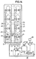
- Fig. 14 shows a fifth embodiment of the invention, in which the pressure control valve 77 leading to the volume chamber 76 is connected to the common supply passage 75 through a return passage 96 which is provided at an intermediate portion thereof with a check valve 88.
- the accumulator 80 is connected to the volume chamber 76 through a regulator 81.
- Fig. 15 shows a sixth embodiment of the invention, in which the pressure control valve 77 leading from the volume chamber 76 is connected to a volume chamber 89 through the return passage 96 which is provided at an intermediate portion thereof with the check valve 88.
- the volume chamber 89 is connected to the common supply passage 75, and also to the accumulator 80 through the regulator 81.
- the consumption of air can be reduced by circulating the relief air to the supply side as in the previous fourth embodiment, and it is possible to restrain, by the volume chamber 89, variations in the air pressure generated in the common supply passage 75 at the time of control by the pressure control valve 77.
- Fig. 16 shows a seventh embodiment of the present invention.
- the air including oil which is released from the air pressure chambers 35 I and 35 E is circulated to the supply side as in the fifth and sixth embodiments, it is possible to utilize the oil included in such circulated air for preventing seizure which may be generated on the sliding surfaces between the lifters 32 I , 32 E and cams 28 I , 28 E by an increase in the temperature of the air pressure chambers 35 I and 35 E .
- the slide holes 29 I and 29 E are provided with ejecting holes 90 I and 90 E , respectively, which are communicated at one end thereof to the intake-side and exhaust-side common supply passages 47 I and 47 E .
- the other ends of the ejecting hole 90 I , 90 E are opened into upper portions of the slide holes 29 I and 29 E , respectively, such that the ejecting holes 90 I , 90 E are opened when the lifters 32 I , 32 E which are pushed by the cams 28 I , 28 E are lowered to their lowermost positions as shown by dotted lines in Fig. 16.
- Fig. 17 shows an eighth embodiment of the invention, in which cylindrical sleeves 91 I , 91 E in which the pistons 27 I and 27 E and the lifters 32 I and 32 E are slidably fitted, are detachably fitted and secured in the pressure component members 26 I and 26 E respectively, by light-press-fitting, for example.
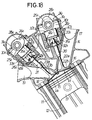
- Fig. 18 shows a ninth embodiment of the invention.
- springs 92 I , 92 E are compressed between the pressure chamber defining members 26 I and 26 E and the pistons 27 I and 27 E in the air pressure chambers 35 I , and 35 E , respectively.
- the spring load of each of the springs 92 I , 92 E is set to be extremely small value which is sufficient for preventing lowering movements of the pistons 27 I and 27 E by pressure drop in the air pressure chambers 35 I , and 35 E , respectively.
- Fig. 19 shows the tenth embodiment of the invention.
- the intake-side and exhaust-side common relief passages 46 I and 46 E are connected to the individual relief passages 44 I , 44 E through orifices 93 I , 93 E , respectively.
- the intake-side and exhaust-side common supply passages 47 I , 47 E are connected to the individual supply passages 45 I , 45 E through orifices 94 I , 94 E , respectively.
- the air pressure in each of the air pressure chambers 35 I and 35 E can be accurately controlled with a good followability with respect to the engine revolution number.
- each of the pressure chamber defining members 26 I and 26 E is integrally formed with all the cylinders, the pressure chamber defining members can be integrally formed with only some of the cylinders among the multi-cylinders.
Landscapes
- Engineering & Computer Science (AREA)
- Mechanical Engineering (AREA)
- General Engineering & Computer Science (AREA)
- Chemical & Material Sciences (AREA)
- Combustion & Propulsion (AREA)
- Valve Device For Special Equipments (AREA)
- Valve-Gear Or Valve Arrangements (AREA)
Description
- The present invention relates to a valve operating system for an internal combustion engine of the type, having air pressure chambers for biasing the engine valves in the closed direction thereof and, in particular, the type having; an air supply passage connected to the air pressure chambers for supplying air thereto and a relief passage connected to the air pressure chambers for releasing air therefrom.
- There is a conventionally known valve operating system in which the pressure in an air pressure chamber is varied in accordance with the operational state of the engine, thereby varyin the load of the air spring on the valve, as described in, e,g., Japanese Patent Application Laid-open No. 230910/90 corresponding to the preamble of
claims 1 and 19. - In such a conventional valve operating system, however, air pressure in the air pressure chamber is controlled at the air-supply side where air is supplied to the air pressure chamber. Therefore, due to a difference in the amount of air flowing into each of a plurality of air pressure chambers which are provided corresponding to respective engine valves of cylinders, as well as due to deviation in the amount of air leaking from each of the air pressure chambers, the actual air pressure in each of the air pressure chambers may be deviated from a target value, or a difference in pressure in the air pressure chambers may become large, which hinders the objective of increasing the maximum number of revolutions of the
- engine. Further, during a transitional stage where the operational state of the engine is changing, the pressure in the air pressure chamber may not be changed swiftly and thus the followability of the valve with the cam may be poor.
- Further, when the known conventional valve operating system is applied to a multi-cylinder type internal combustion engine, one pressure chamber defining member is secured to the cylinder head with respective to each cylinder and a piston which is operatively connected to the cam shaft common to all the cylinders and which is secured to an engine valve for each cylinder is slidably received in each pressure chamber defining member to define an air chamber between each pressure chamber defining member and the piston. Therefore, passages which should be connected to each of the air pressure chambers are connected to each of the pressure chamber defining members. Thus, the number of parts is increased, the structure becomes complicated, and sealability becomes poor. Moreover, the cam shaft is rotatbly supported by a can holder which is mounted to the cylinder head between each of the pressure chamber defining members and thus, the construction becomes more complicated.
- The present invention has been developed in view of the above problems, and it is an objet of the invention to provide a valve operating system for an internal combustion engine which can precisely control the pressure in the pressure chamber and can improve the responsiveness of the system, during a transitional stage where the operation state of the engine is changing.
- To achieve the above object, according to the present invention a valve operating system comprises the features of
claims 1 and 19. The pressure control valve for controlling the pressure in the air pressure chamber is connected to the relief valve, thereby controlling such pressure in the air pressure chamber by the pressure control valve which is closer to the relief valve. Accordingly, the accuracy of the operation of the relief valve is improved to precisely balance the pressure among the plurality of air pressure chambers and thus, the responsiveness for controlling the pressure in the air pressure chambers during changing the operational state of the engine can be improved. - It is an another object of the invention to provide a valve operating system of this type for an internal combustion engine which can reduce the number of parts and simplify the structure, and a high reliability in the sealability can be obtained. To achieve this object, the engine has a plurality of cylinders and a pressure chamber defining member is secured to the cylinder head of the engine so as to correspond to all or some of the plurality of cylinders; a cam shaft common to all the cylinders is operatively connected with the pistons, each of which is secured to an engine valve for each of the cylinders; the pistons are each slidably received in the pressure chamber defining member, and each of the pressure chamber defining members being provided, commonly for all of the air pressure chambers, with a passage which forms portions of the air relief passage and the air supply passage, respectively, and with a bearing portion for rotatbly supporting the cam shaft.
- The above and other objects, features and advantages of the invention will become apparent from the following description of the preferred embodiments, taken in conjunction with the accompanying drawings.
-
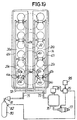
- Figs. 1 to 10 show a first embodiment of the present invention, wherein
- Fig. 1 is a schematic plan view of a valve operating system of the invention;
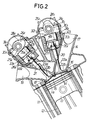
- Fig. 2 is a sectional view of the system taken along line 2-2 in Fig. 1;
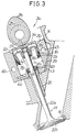
- Fig. 3 is an enlarged longitudinal sectional view of an essential portion of Fig. 2;
- Fig. 4 is a partial plan view of component members of a pressure chamber;
- Fig. 5 is a partial perspective view of the component members of the pressure chamber;
- Fig. 6 is a sectional view of the valve operating system taken along line 6-6 in Fig. 1;
- Fig. 7 is a side view of an internal combustion engine taken in the direction of
arrow 7 shown in Fig. 1; - Fig. 8 is an enlarged sectional view taken along line 8-8 in Fig. 7;
- Fig. 9 is a graph showing variations in the pressure in the air pressure chamber with respective to the engine revolution number;
- Fig. 10 is a graph showing variations in a target air pressure caused by variations in the pressure in an accumulator:
- Fig. 11 is similar to Fig. 1 but illustrates a schematic plan view of a valve operating system according to a second embodiment of this invention;
- Fig. 12 is a sectional view of a volume chamber according to a third embodiment;
- Fig. 13 is a graph showing variations in the pressure in the air pressure chamber with respective to the engine revolution number according to a fourth embodiment;
- Fig. 14 is similar to Fig. 1 but illustrates a schematic plan view of a valve operating system according to a fifth embodiment of this invention;
- Fig. 15 is similar to Fig. 1 but illustrates a schematic plan view of a valve operating system according to a sixth embodiment of this invention;
- Fig. 16 is similar to Fig. 2 but illustrates a longitudinal sectional view of a valve operating system according to a seventh embodiment of this invention;
- Fig. 17 is similar to Fig. 2 but illustrates a longitudinal sectional view of a valve operating system according to an eighth embodiment of this invention;
- Fig. 18 is similar to Fig. 2 but illustrates a longitudinal sectional view of a valve operating system according to a ninth embodiment of this invention; and
- Fig. 19 is similar to Fig. 1 but illustrates a schematic plan view of a valve operating system according to a tenth embodiment of this invention.
- A first embodiment of the present invention will now be described with reference to Figs. 1 to 10.
- In Figs. 1 and 2, four
cylinders 12 are arranged in series in acylinder block 11 of a four-cylinder internal combustion engine. In each of thecylinders 12, acombustion chamber 15 is formed between apiston 13 slidably received in eachcylinder 12 and acylinder head 14 coupled to an upper surface of thecylinder block 11. Further, with respect to each of thecylinders 12, provided in thecylinder head 14 are a pair ofintake valve openings 16 in the ceiling surface of thecombustion chamber 15, anintake port 17 commonly leading to both theintake valve openings 16, a pair ofexhaust valve openings 18 in the ceiling surface of thecombustion chamber 15, and anexhaust port 19 commonly leading to both theexhaust valve openings 18. A plurality of intake valves VI are guided for vertical movement byguide cylinders 20 which are mounted in thecylinder head 14 for opening and closing the respectiveintake valve openings 16. A plurality of exhaust valves VE are guided for vertical movement byguide cylinders 21 which are mounted in thecylinder head 14 for opening and closing the respectiveexhaust valve openings 18. - Each of the intake valves VI is comprised of a
valve stem 22a which is slidably passed through theguide cylinder 20, and avalve body 22b mounted to a tip end of thevalve stem 22a for opening and closing theintake valve opening 16. - Each of the intake valves VI is opened and closed by an intake-side valve operating system 24I, and each of the exhaust valves VE is opened and closed by an exhaust-side valve operating system 24E. Since both the intake-side and exhaust-side valve operating systems 24I and 24E have basically the same structure, only the structure of the intake-side system 24I, will be described in detail below. Each of component elements of the intake-side valve operating system 24I, will be indicated by a numeral reference with a subscript letter "I" added thereto. As to the exhaust-side valve operating system 24E, the corresponding component elements thereof are illustrated in the drawings with the same numerals as those of the system 24I but with a subscript letter "E" added thereto and will not be described.
- In Fig. 3, the intake-side valve operating system 24I comprises; a cam shaft 25I having an axis perpendicular to that of the
valve stem 22a of each of the intake valves VI is commonly disposed for all of thecylinders 12; a pressure chamber defining member 26I which is fixed to thecylinder head 14; and apiston 271 which is operatively connected to the cam shaft 25I and fixed to each intake valves VI. The pistons 27I are slidably received in the pressure chamber defining member 26I. - The cam shaft 25I is rotated by a crankshaft (not shown) at a reduction ratio of 1/2, and is disposed above the intake valves VI. Further, the cam shaft 25I is integrally provided with cams 28I at positions corresponding to each of the intake valves VI.
- Referring also to Figs. 4 and 5, the pressure chamber defining member 26I is common for all the
cylinders 12, and is formed in a rectangular block-like shape along the series ofcylinders 12, and coupled to thecylinder head 14 at a position corresponding to the intake valves VI. The pressure chamber defining member 26I is provided with a plurality of slide holes 29I which correspond to each of the intake valves VI (in this embodiment, there are four pairs of slide holes 29I, one pair for each cylinder 12). The slide holes 29I are opened upwardly in the pressure chamber defining member 26I and are coaxial with thevalve stems 22a of the intake valves VI. A rear end, i.e., an upper end, of each of thevalve stems 22a is oil-tightly and movably passed through a bottom portion of the pressure chamber defining member 26I, and is coaxially projected into the slide hole 29I. - Semi-circular bearing portions 30I for supporting the lower half of the cam shaft 25I are provided on an upper portion of the pressure chamber defining member 26I at positions between
adjacent cylinders 12 as well as at longitudinally opposite ends of the member 26I. Holders 31I are coupled to upper portions of the respective bearing portions 30I for rotatably supporting upper half of the cam shaft 25I in cooperation with the respective bearing portions 30I. - A bottomed cylindrical lifter 32I is slidably received in each of the slide holes 29I with the closed end of the lifter 32I facing up. Therefore, the outer surface of the closed end of the lifter 32I comes into sliding contact with the cam 28I and the inner surface of the closed end of the lifter 32I abuts against the rear end, i. e., the upper end, of the
valve stem 22a of the intake valve VI. In other words, the lifter 32I is interposed between the cam 28I and thevalve stem 22a. - The piston 27I is secured to the upper end portion of the
valve stem 22a. The piston 27I is slidably received in the slide hole 29I through an annular seal member 33I made of resilient material, and is inserted in the lifter 32I to define an air chamber 34I between the piston 27I itself and the closed end of the lifter 32I. An air pressure chamber 35I is defined between the piston 27I and a bottom portion of the slide hole 29I. The piston 27I is formed into a double cylindrical shape whose upper end closer to the lifter 32I is occluded. The piston 27I is provided, around an outer surface thereof above the seal member 33I, with an O-ring 36I for sliding contact with an inner surface of the lifter 32I. - The
valve stem 22a is provided at an upper end portion thereof with an annular engaging groove 37I. The piston 27I is fixed to the upper end portion of thevalve stem 22a through a split cotter 38I which engages the engaging groove 37I. Further, in order to prevent a leakage of pressurized air into the air chamber 34I from between the piston 27I and outer surfaces of the cotter 38I as well as between the piston 27I and thevalve stem 22a, a seal member 39I for thevalve stem 22a is provided inside the piston 27I below the cotter 38I. - A bottom portion of the slide hole 29I, i.e., a lower end portion of the pressure chamber defining member 26I is coaxially provided with a cylindrical portion 40I projecting into the air pressure chamber 35I. The cylindrical portion 40I is integrally provided at an upper end thereof with a radially inwardly extended flange 42I. A hole 41I is defined by an inner edge of the flange through which the
valve stem 22a is movably passed. An upper portion of theguide cylinder 20 is inserted into the cylindrical portion 40,. An annular valve stem seal member 43I is received in the cylindrical portion 40I such that the valve stem seal member 43I is clamped between theguide cylinder 20 and the flange 42I. - With respect to each of the air pressure chambers 35I, an individual relief passage 44I leading from a lower portion of each air pressure chamber 35I, and an individual supply passage 45I leading from an intermediate portion of each air pressure chamber 35I are provided in the pressure chamber defining member 26I. The pressure chamber defining member 26I is provided at one side thereof along the series of slide holes 29I with an intake-side common relief passage 46I which is common for all the air pressure chambers 35I. One end of the relief passage 46I is closed. The pressure chamber defining member 26I is also provided at the other side along the series of slide holes 29I of the pressure chamber defining member 26I with an intake-side
common supply passage 47I which is common for all the air pressure chambers 35I. One end of thesupply passage 47I is closed. - Referring also to Fig. 6, with respect to each of the
cylinders 12, a relief valve 48I is interposed between the intake-side common relief passage 46I and the two individual relief passages 44I leading to the two slide holes 29I, i.e., the two air pressure chambers 35I. Also, with respect to each of thecylinders 12, a check valve 49I is interposed between the intake-sidecommon supply passage 47I and two individual supply passages 45I leading to the two slide holes 29I, i.e., two air pressure chambers 35I. - Each of the relief valves 48I is disposed in the pressure chamber defining member 26I at a position corresponding to the intake-side common relief passage 46I, and between the two slide holes 29I, i.e., the two air pressure chambers 35I, which are paired for each of the
cylinders 12. The relief valve 48I comprises a valve bore 51I commonly leading to the two individual relief passage 44I, a spherical valve body 53I biased by a spring 52I in a closed direction of the valve bore 51I, and a valve chest 54I for containing therein the valve body 53I and leading to the intake-side common relief passage 46I. The spring 52I is compressed between the valve body 53I and a screw member 55I which is threadedly engaged in the pressure chamber defining member 26I. - The relief valve 48I is adapted to open to release air including oil from the air pressure chamber 35I when oil in the air pressure chamber 35I exceeds a predetermined amount and the pressure in the air pressure chamber 35I becomes higher than that in the intake-side common relief passage 46I by a predetermined value (e.g., 1kgf/cm2) or more.
- Each of the check valves 49I is disposed in the pressure chamber defining member 26I at a position corresponding to the intake-side
common supply passage 47I and between the two slide holes 29I, i.e., the two air pressure chambers 35I which are paired for each of thecylinders 12. The check valve 49I comprises a valve bore 65I leading to the intake-sidecommon supply passage 47I, a spherical valve body 57I biased by a spring 56I in a closed direction of the valve body 57I, and a valve chest 58I for containing therein the valve body 57I and commonly leading to the two individual supply passage 45I. The spring 56I is compressed between the valve body 57I and a screw member 59I which is threadedly engaged in the pressure chamber defining member 26I. - The check valve 49I is adapted to open to supplement pressurized air to the air pressure chamber 35I when air pressure in the air pressure chamber 35I becomes lower than that in the intake-side
common supply passage 47I by a given value (e.g., 1kgf/cm2) or more. - In Figs. 7 and 8, the other end of the intake-side common relief passage 46I, i.e., the end which is not closed, is opened toward an
end wall 14a of thecylinder head 14 at one end in the direction of the in-line series ofcylinders 12, and is provided with a large-diameter portion 61I. A mountingmember 63 having afitting hole 62 which has the same diameter as that of the large-diameter portion 61I and is coaxial therewith is threaded into theend wall 14a. Anannular seal member 64 is interposed between the mountingmember 63 and theend wall 14a for surrounding the threaded portion therebetween. - A cylindrical joint 65 is received at opposite ends thereof into the large-diameter portion 61I and the
fitting hole 62, respectively. The joint 65 is provided at one end outer surface thereof with a pair ofannular seal members 66 for sealing contact with an inner surface of the large-diameter portion 61I, and is provided at the other end outer surface of the joint 65 with a pair ofannular seal members 67 for sealing contact with an inner surface of thefitting hole 62. - A
cylindrical projection 63a which is coaxial with thefitting hole 62 is projected outwardly from astep 63b of the mountingmember 63, and abolt 68 is threaded into a tip end of theprojection 63a. A ring-like connect member 70 defines between thismember 70 itself and theprojection 63a an annular chamber 69 leading to the joint 65, and is clamped between thestep 63b and thebolt 68. Anannular seal member 98 is interposed between thestep 63b and theconnect member 70, and anotherannular seal member 99 is interposed between thebolt 68 and theconnect member 70. Further, theconnect member 70 is integrally provided withconnect tubes - The exhaust-side common relief passage 46E in the exhaust-side valve operating system 24E has the same structure as the intake-side common relief passage 46I in the intake-side valve operating system 24I, and is communicated to a connect member 71 which is mounted to the
end wall 14a of thecylinder head 14. A connect tube 71a of the connect member 71 and theconnect tube 70a of theconnect member 70 are connected to each other through aconnect passage 72. Further, a singlecommon relief passage 73 which is common for both the intake-side and exhaust-side valve operating systems 24I and 24E is connected to theconnect tube 70b of theconnect member 70. - End portions of both the intake-side
common supply passage 47I of the intake-side valve operating system 24I and the exhaust-sidecommon supply passage 47E of the exhaust-side valve operating system 24E have the same structure as those of the intake-side and exhaust-side common relief passages 46I and 46E, and are connected to each other through theconnect passage 74, and connected to a singlecommon supply passage 75 which is common for both the intake-side and exhaust-side valve operating systems 24I and 24E. - Referring again to Fig. 1, the
common relief passage 73 is disposed so that an end thereof faces a valve operating chamber between thecylinder block 11 and thecylinder head 14. Apressure control valve 77 which is a very accurate solenoid valve is connected to the end of thecommon relief passage 73. Further, thecommon relief passage 73 is provided at an intermediate portion thereof with relief pressure detecting means 78 for detecting a pressure in thecommon relief passage 73, i.e., a relief pressure. - The
common supply passage 75 is connected to anaccumulator 80 through aregulator 81, and constantly pressurized air is supplied to thecommon supply passage 75 and thus, to both the intake-side and exhaust-sidecommon supply passages accumulator 80 is provided with accumulator internal pressure detecting means 82 for detecting the internal pressure of theaccumulator 80. - The opening and closing operation of the
pressure control valve 77 is controlled by acontrol unit 79. The value detected by the reliefpressure detecting means 78, the value detected by the accumulator internalpressure detecting means 82 and a value detected by revolution number detecting means 95 for detecting the engine revolution number are inputted to thiscontrol unit 79. - The
control unit 79 is adapted to control the opening and closing operation of thepressure control valve 77 such that the pressure in thecommon relief passage 73, i.e., a value detected by the reliefpressure detecting means 78 becomes equal to a set value. This set value is a value which is obtained by subtracting an opening valve set pressure of both the relief valves 48I and 48E from the air pressure target value of the air pressure chambers 35I and 35E. The air pressure target value is set in accordance with the engine revolution number representing the engine operational state. Thus, the air pressure in the air pressure chambers 35I and 35E is controlled into a target value in accordance with the operational state of the engine. - Further, when the engine revolution number becomes equal to or larger than a preset revolution number NET as shown by graph (a) in Fig. 9, the
control unit 79 is turned off, i.e., assumes a state in which thepressure control valve 77 is kept closed and the pressure is not controlled, as shown by graph (b) in Fig. 9. By this arrangement, pressure in each of the air pressure chambers 35I and 35E is swiftly increased as shown by graph (c) in Fig. 9 when the engine revolution number is equal to or larger than the set revolutional number NET. - The
control unit 79 is adapted such that, when the internal pressure of theaccumulator 80 becomes smaller than the set pressure PT, the target air pressure in the air pressure chambers 35I and 35E is changed to a value larger than the target value which was obtained when the internal pressure in theaccumulator 80 was equal to or larger than the set pressure PT, as shown by graph (a) in Fig. 10. - The operation of the first embodiment will now be described. In the intake-side and exhaust-side valve operating systems 24I and 24E, when the cam shafts 25I and 25E are driven for rotation by the crankshaft, the lifters 32I and 32E are pressed downwardly as they come into sliding contact with lobe portions of the cams 28I and 28E, thereby to depress the valve stems 22a and 23a of the intake and exhaust valves VI and VE, respectively, to separately open both the intake and exhaust valves VI and VE.
- At this time, the pistons 27I and 27E which are secured to the upper end portions of the valve stems 22a and 23a are also pressed downwardly while reducing the volumes of the air pressure chambers 35I and 35E, thereby generating air pressure in the air pressure chambers 35I and 35E. This causes the intake valve VI and the exhaust valve VE to be biased upwardly, i.e., in their closed directions by the air pressure, and the cams 28I and 28E are driven to open the intake valve VI and the exhaust valve VE against the biasing forces toward their closed directions by the air pressure.
- By such structure in which the intake valve VI and the exhaust valve VE are biased in their closed directions by the air pressure as described above, it is possible to rotate the engine at higher speed as compared with an engine of a structure in which such intake and exhaust valves are closed by valve springs, because it is unnecessary to take into account a limit of resonance by natural vibration or oscillation.
- In the valve operation system of the present invention, air pressure in the air pressure chambers 35I and 35E are controlled at the air-relief side. Therefore, as compared with the conventional system in which such air pressure is controlled at the air-supply side, it is possible to maintain a difference between the internal pressure of the air pressure chambers 35I, 35E and the pressure at the air-relief side to a lower degree, thereby improving the operating accuracy of each of the relief valves 48I and 48E. Thus, the pressures in the plurality of air pressure chambers 35I and 35E can be balanced precisely, which makes it possible to improve the responsiveness of the valve operating system when the target value of the air pressure of each of the air pressure chambers 35I and 35E is varied in accordance with the operational condition of the engine.
- Furthermore, since the
pressure control valve 77 is connected to the singlecommon relief passage 73 which is common for the plurality of the air pressure chambers 35I and 35E, it is possible to precisely control pressures in the plurality of air pressure chambers 35I and 35E by the singlepressure control valve 77. Thus, the structure of the system can be simplified and the amount of consumption of the pressured air can be reduced as compared with the conventional system in which air released from each of the air pressure chambers 35I and 35E is individually released to outside. - As is shown in Fig. 9, the control of the
pressure control valve 77 by thecontrol unit 79 is stopped when the revolution number of the engine becomes equal to or larger then the set revolution number NET. Therefore, in such a case, the pressure in the air pressure chambers 35I and 35E can swiftly be increased and adapted to such variation in the engine revolution number and thus, an appropriate spring load in accordance with the engine revolution number can be obtained. - Further, when the internal pressure of the
accumulator 80 is decreased lower than the set pressure PT, the target air pressures of the air pressure chambers 35I and 35E are changed to higher values as shown in Fig. 10. Therefore, when the internal pressure of theaccumulator 80 is decreased, the amount of relief air is decreased, thereby preventing an abrupt drop of the internal pressure of theaccumulator 80 and thus, the necessary spring load can be maintained. - In the valve operating systems 24I and 24E as described above, the pressure chamber defining members 26I and 26E are provided for all the
cylinders 12, and the intake-side and exhaust-side common relief passages 46I and 46E as well as the intake-side and exhaust-sidecommon supply passages common supply passages - Further, end portions of the intake-side and exhaust-side common relief passages 46I and 46E as well as end portions of the intake-side and exhaust-side
common supply passages common relief passage 73 and thecommon supply passage 75, respectively, through the cylindrical joint 65 or the like which are fitted in theend wall 14a of thecylinder head 14 via theseal members cylinder head 14 can be accommodated, thereby to allow the relief and supply of the pressured air. - Furthermore, by providing the bearing portions 30I, 30E for supporting the cam shafts 25I, 25E on the pressure chamber defining members 26I and 26E, respectively, it is possible to maintain a high rigidity against the thrust force caused by the rotation of the cam shaft 25I, 25E, and to increase the allowable revolution number of the engine and the lift amount of the valves.
- The individual relief passages 44I, 44E which are connected to the intake-side and exhaust-side common relief passages 46I, 46E through the relief valves 48I, 48E, respectively, are opened into the lower portions of the air pressure chambers 35I and 35E, respectively. Thus, when oil in the air pressure chamber 35I and 35E is increased by a given amount so that the internal pressure of these chambers becomes equal to or larger than the predetermined maximum pressure, priority is given to such increased oil to be released first to avoid wasteful release of air and thus, wasteful consumption of the pressured air from the
accumulator 80 can be avoided. - Fig. 11 shows a second embodiment of the present invention, and the similar reference numerals are given to components corresponding to components of the previous first embodiment.
- A
volume chamber 76 having reliefpressure detecting means 78 is mounted in an intermediate portion of thecommon relief passage 73. Apressure control valve 77 is connected to thecommon relief passage 73 at a portion downstream of thevolume chamber 76. - With such a structure, since the internal pressure of the
volume chamber 76 which is mounted in the intermediate portion of thecommon relief passage 73 is controlled by thepressure control valve 77, any pulse of the relief pressure can be eliminated. Thus, variations can be avoided in the air pressure in the air pressure chamber 35I and 35E in any of the cylinders that may have an adverse influence on air pressure chamber 35I and 35E in other cylinders. Besides, the pressure in each of the air pressure chambers 35I, and 35E can be controlled more precisely. - Fig. 12 shows a third embodiment of the present invention. In this embodiment, a
closed casing 83 defines therein thevolume chamber 76 described with respect to the second embodiment. Thecasing 83 is provided at one side thereof with a connectinghole 84 leading to thecommon relief passage 73, and at the other side thereof with the reliefpressure detecting means 78. Thepressure control valve 77 is connected, through afilter 86, to arelief hole 85 which is opened into a bottom portion of thecasing 83. Apartition plate 87 which is upwardly obliqued toward the connectinghole 84 is secured to the bottom portion of thecasing 83 along its entire width so as to cover therelief hole 85. - With such a structure, oil included in the air which is introduced into the
volume chamber 76 from thecommon relief passage 73 through the connectinghole 84 can be saved in thevolume chamber 76 between the connectinghole 84 and thepartition plate 87. Therefore, it is possible to release oil first from therelief hole 85 when thepressure control valve 77 is opened and thus, wasteful release of air can be- avoided to the utmost. Also, releasing only oil is effective for preventing a degradation of thepressure control valve 77. - Fig. 13 shows a fourth embodiment of the present invention. In this embodiment, the pressure of the supplied air is controlled in two stages (or multi-stages) as shown by graph (b) in accordance with the engine revolution number exceeding a set engine revolution number NET. With such arrangement, the pressure in the air pressure chambers 35I and 35E is varied as shown by graph (c), and when the engine revolution number is varied substantially, the pressure in the air pressure chambers 35I and 35E can be controlled with better responsiveness in two stages (or multi-stages).
- Fig. 14 shows a fifth embodiment of the invention, in which the
pressure control valve 77 leading to thevolume chamber 76 is connected to thecommon supply passage 75 through areturn passage 96 which is provided at an intermediate portion thereof with acheck valve 88. Theaccumulator 80 is connected to thevolume chamber 76 through aregulator 81. - By this fifth embodiment, since the highly pressurized air which is controlled by the
pressure control valve 77 and released from thevolume chamber 76 is returned to thecommon supply passage 75, air is consumed only by the amount equal to that air which leaked from the air pressure chambers 35I and 35E and thus, the amount of air supplied from theaccumulator 80 can largely be reduced. - Fig. 15 shows a sixth embodiment of the invention, in which the
pressure control valve 77 leading from thevolume chamber 76 is connected to avolume chamber 89 through thereturn passage 96 which is provided at an intermediate portion thereof with thecheck valve 88. Thevolume chamber 89 is connected to thecommon supply passage 75, and also to theaccumulator 80 through theregulator 81. - By this sixth embodiment, the consumption of air can be reduced by circulating the relief air to the supply side as in the previous fourth embodiment, and it is possible to restrain, by the
volume chamber 89, variations in the air pressure generated in thecommon supply passage 75 at the time of control by thepressure control valve 77. - Fig. 16 shows a seventh embodiment of the present invention. According to this embodiment, when the air including oil which is released from the air pressure chambers 35I and 35E is circulated to the supply side as in the fifth and sixth embodiments, it is possible to utilize the oil included in such circulated air for preventing seizure which may be generated on the sliding surfaces between the lifters 32I, 32E and cams 28I, 28E by an increase in the temperature of the air pressure chambers 35I and 35E.
- In Fig. 16, the slide holes 29I and 29E are provided with ejecting
holes common supply passages hole - By this seventh embodiment, when each of the intake and exhaust valves VI, VE is opened, oil including air therein is ejected from the ejecting
hole common supply passages - Fig. 17 shows an eighth embodiment of the invention, in which cylindrical sleeves 91I, 91E in which the pistons 27I and 27E and the lifters 32I and 32E are slidably fitted, are detachably fitted and secured in the pressure component members 26I and 26E respectively, by light-press-fitting, for example.
- By this eighth embodiment, if the sleeves 91I, 91E become worn by friction with the pistons 27I and 27E and the lifters 32I, 32E, the sleeves 91I, 91E can be replaced.
- Fig. 18 shows a ninth embodiment of the invention. In this embodiment, springs 92I, 92E are compressed between the pressure chamber defining members 26I and 26E and the pistons 27I and 27E in the air pressure chambers 35I, and 35E, respectively. The spring load of each of the springs 92I, 92E is set to be extremely small value which is sufficient for preventing lowering movements of the pistons 27I and 27E by pressure drop in the air pressure chambers 35I, and 35E, respectively.
- By this ninth embodiment, even if the internal pressures of the air pressure chambers 35I, and 35E are reduced such as when the engine has been left for a long time, it is possible to prevent the lowering movements of the pistons 27I and 27E, thereby to prevent the cotter 38I from slipping off and to avoid dropping off of the intake and exhaust valves VI and VE. Further, at a time of low rotation of the engine such as when starting of the engine, a high air pressure is unnecessary, and the engine can be operated with a reduced friction loss by utilizing the spring forces of the springs 92I, 92E.
- Fig. 19 shows the tenth embodiment of the invention. In this embodiment, the intake-side and exhaust-side common relief passages 46I and 46E are connected to the individual relief passages 44I, 44E through orifices 93I, 93E, respectively. And the intake-side and exhaust-side
common supply passages - By this tenth embodiment, the air pressure in each of the air pressure chambers 35I and 35E can be accurately controlled with a good followability with respect to the engine revolution number.
- In the above described embodiments, although each of the pressure chamber defining members 26I and 26E is integrally formed with all the cylinders, the pressure chamber defining members can be integrally formed with only some of the cylinders among the multi-cylinders.
Claims (20)
- A valve operating system for an internal combustion engine, comprising an air pressure chamber (35) for biasing an engine valve (V) in a closed direction thereof; an air supply passage (75,47,45) connected to said air pressure chamber (35) for supplying air to the air pressure chamber (35) ; and a relief passage (44,46,73) including a relief valve (48) connected to said air pressure chamber (35) for releasing air from the air pressure chamber (35),characterized inthat a pressure control valve (77) is connected to said relief passage (44, 46,73) for controlling the level of pressure to cause opening of said relief valve (48) for releasing air from said air pressure chamber (35).
- A valve operating system for an internal combustion engine according to claim 1, wherein said engine has a plurality of cylinders (12) and said relief passage (44, 46, 73) comprises individual relief passages (44) individually connected to a said air pressure chamber (35) for each of said plurality of cylinders (12), and a single common relief passage (46, 73) commonly connected to said individual relief passages (44), said pressure control valve (77) being connected to said common relief passage (46, 73).
- A valve operating system for an internal combustion engine according to claim 2, wherein said common relief passage (46, 73) is provided at an intermediate portion thereof with a volume chamber (76), said pressure control valve (77) being connected to said common relief passage (46, 73) at a position downstream of said volume chamber (76).
- A valve operating system for an internal combustion engine according to claim 3, wherein said volume chamber (76) is provided therein with separating means (87) for separating oil from air.
- A valve operating system for an internal combustion engine according to claim 1, further comprising relief pressure detecting means (78) for detecting a pressure in said relief passage (46, 73), and a control unit (79) which controls an opening and closing operation of said pressure control valve (77) as to maintain air pressure in said air pressure chamber (35) at a target value on the basis of a value detected by said relief pressure detecting means (78), and wherein said control unit (79) stops the opening operation of said pressure control valve (77) when said target value is changed to a larger value.
- A valve operating system for an internal combustion engine according to claim 5, wherein an accumulator (80) including accumulator internal pressure detecting means (82) is connected to said air supply passage (75, 47, 45), and wherein said control unit (79) is arranged, when a value detected by said accumulator internal detecting means (82) smaller than a predetermined value, to change said target value to a larger value than that when the value detected by said accumulator internal detecting means (82) was equal to or larger than said predetermined value.
- A valve operating system for an internal combustion engine according to claim 1, wherein said pressure control valve (77) is connected at an exit side thereof to said air supply passage (75, 47, 45) through a return passage (96), said return passage (96) being provided at an intermediate portion thereof with a check valve (88).
- A valve operating system for an internal combustion engine according to claim 1, wherein said engine has a plurality of cylinders (12) and a pressure chamber defining member (26) is secured to a cylinder head (14) of the engine so as to correspond to at least some of said plurality of cylinders (12); a cam shaft (25) common to said at least some of the cylinders (12) is operatively connected with pistons (27), each of which is secured to an engine valve (V), for each of said at least some of the cylinders (12); said pistons (27) are each slidably received in said pressure chamber defining member (26) to define said air pressure chamber (35) between said piston (27) and said pressure chamber defining member (26), and said pressure chamber defining member (26) being provided, commonly for all of said air pressure chambers (35), with passage means (46, 47) which form portions of said relief passage (44, 46, 73) and said air supply passage (75, 47, 45), respectively.
- A valve operating system for an internal combustion engine according to sleeves (91) in engine according to claim 8, wherein a plurality of sleeves (91) in which said respective pistons (27) are slidably fitted are detachably fitted and secured to said pressure chamber defining member (26).
- A valve operating system for an internal combustion engine according to claim 8, wherein bearing means (30) are formed in said pressure chamber defining member (26) for rotatably supporting said cam shaft (25).
- A valve operating system for an internal combustion engine according to claim 1, wherein a relief valve (48) is provided in said relief passage (44, 46, 73) upstream of said pressure control valve (77).
- A valve operating system for an internal combustion engine according to claim 11, wherein an individual relief passage (44) connects each of two adjacent air pressure chambers (35) to said relief valve (48).
- A valve operating system for an internal combustion engine according to claim 12, wherein said two adjacent air pressure chambers (35) are for two either intake or exhaust valves (VI, VE) for a cylinder (12) of the internal combustion engine.
- A valve operating system for an internal combustion engine according to claim 1, wherein a supply check valve means (49) is provided between each air pressure chamber (35) and said air supply pasage (75, 47).
- A valve operating system for an internal combustion engine according to claim 1, wherein an intake valve (VI) and an exhaust valve (VE) are provided as said engine valve, wherein said air pressure chamber (35), said air supply passage (47,45), said relief passage (44,46) and said relief valve (48) are provided for each of said intake valve and said exhaust valve, and wherein a relief passage (44I, 46I) is provided for the intake valve side and a further relief passage (44E, 46E) is provided for the exhaust valve side.
- A valve operating system for an internal combustion engine according to claim 15, wherein said pressure control valve (77) is provided commonly for said intake side relief passage (44I, 46I) and said exhaust side relief passage (44E, 46E).
- A valve operating system for an internal combustion engine according to claim 1, wherein said engine has a plurality of cylinders (12), wherein an intake valve (VI) and an exhaust valve (VE) are provided as said engine valve for each of said cylinders (12), wherein said air pressure chamber (35), said air supply passage (47, 45), said relief passage (44, 46) and said relief valve (48) are provided for each of said intake valve and said exhaust valve, and wherein said relief passage comprises relief passages (44I, 46I) for the intake valves of the cylinders and further relief passages (44E, 44E) for the exhaust valves of the cylinders.
- A valve operating system for an internal combustion engine according to claim 17, wherein said pressure control valve (77) is provided commonly for said intake side relief passages (44I, 46I) and said exhaust side relief passages (44E, 46E).
- A valve operating system for an internal combustion engine, comprising a plurality of cylinders (12); a plurality of air pressure chambers (35) for biasing respective engine valves (V) of each of said cylinders (12) in a closed direction thereof; an air supply passage (75, 47, 45) connected to said air pressure chambers (35) for supplying air to the air pressure chambers (35); a plurality of individual relief passages (44) respectively connected to said air pressure chambers (35) for releasing air from the air pressure chambers (35),characterized bya single common relief passage (46, 73) connected between each of said individual relief passages (44) and a pressure control valve (77) for adjustably determining the level of pressure to be released from said air pressure chambers (35) through said relief passages (44).
- A valve operating system for an internal combustion engine according to claim 17, wherein said individual relief passages (44) contain individual pressure relief valves (48) .
Applications Claiming Priority (4)
| Application Number | Priority Date | Filing Date | Title |
|---|---|---|---|
| JP209141/91 | 1991-08-21 | ||
| JP20914191A JPH0552103A (en) | 1991-08-21 | 1991-08-21 | Valve drive system for multi-cylinder internal combustion engine |
| JP24044391A JPH0559916A (en) | 1991-08-27 | 1991-08-27 | Air valve spring system for internal combustion engine |
| JP240443/91 | 1991-08-27 |
Publications (2)
| Publication Number | Publication Date |
|---|---|
| EP0536513A1 EP0536513A1 (en) | 1993-04-14 |
| EP0536513B1 true EP0536513B1 (en) | 1996-07-03 |
Family
ID=26517249
Family Applications (1)
| Application Number | Title | Priority Date | Filing Date |
|---|---|---|---|
| EP92114249A Expired - Lifetime EP0536513B1 (en) | 1991-08-21 | 1992-08-20 | Valve operating system for internal combustion engine |
Country Status (3)
| Country | Link |
|---|---|
| US (1) | US5233950A (en) |
| EP (1) | EP0536513B1 (en) |
| DE (1) | DE69211942T2 (en) |
Cited By (4)
| Publication number | Priority date | Publication date | Assignee | Title |
|---|---|---|---|---|
| US5553572A (en) * | 1993-09-30 | 1996-09-10 | Sony Corporation | Multi-valve engine |
| US5664527A (en) * | 1993-10-29 | 1997-09-09 | Automobiles Peugeot | Pneumatic valve recoil system for internal combustion engines |
| EP0824180A1 (en) | 1996-08-13 | 1998-02-18 | Bayerische Motoren Werke Aktiengesellschaft, Patentabteilung AJ-3 | Pneumatic return spring for engine valve |
| CN104514622A (en) * | 2013-10-07 | 2015-04-15 | 谭文 | Storage room energy saving motor |
Families Citing this family (11)
| Publication number | Priority date | Publication date | Assignee | Title |
|---|---|---|---|---|
| US5695430A (en) * | 1994-09-21 | 1997-12-09 | Moyer; David F. | Hybrid internal combustion engine |
| JP3145591B2 (en) * | 1994-11-16 | 2001-03-12 | ヤマハ発動機株式会社 | Vehicle compressed air supply system |
| WO1997009516A1 (en) * | 1995-09-01 | 1997-03-13 | Serge Vallve | Pneumatic engine valve assembly |
| DE19733186A1 (en) * | 1997-07-31 | 1999-02-04 | Fev Motorentech Gmbh & Co Kg | Gas exchange valve apparatus for piston engine |
| AUPQ491099A0 (en) * | 1999-12-30 | 2000-02-03 | Ward, Antony John Fowler | Internal combustion engine |
| DE10031233A1 (en) * | 2000-06-27 | 2002-03-21 | Fev Motorentech Gmbh | Electromagnetically actuated gas exchange valve with pneumatic return springs for a piston internal combustion engine |
| FR2867807B1 (en) * | 2004-03-17 | 2006-07-07 | Intertechnique Sa | DEVICE FOR RECALLING A VALVE AND MOTOR EQUIPPED WITH SUCH A DEVICE |
| DE502005004913D1 (en) * | 2005-11-10 | 2008-09-11 | Man B & W Diesel As | TWO STROKE BIG DIESEL ENGINE |
| US20070215078A1 (en) * | 2006-02-21 | 2007-09-20 | Sturman Digital Systems, Llc | Methods and apparatus to use engine valves as both intake and exhaust valves |
| EP2208870B1 (en) | 2009-01-20 | 2013-03-27 | BRP-Powertrain GmbH & Co. KG | Air spring system for an internal combustion engine |
| EP2211031B1 (en) * | 2009-01-22 | 2013-07-10 | BRP-Powertrain GmbH & Co. KG | Air spring with cap |
Family Cites Families (10)
| Publication number | Priority date | Publication date | Assignee | Title |
|---|---|---|---|---|
| FR2364328A1 (en) * | 1976-09-09 | 1978-04-07 | Chrysler France | Valve operation for four-stroke IC engine - has spring return aided by adiabatic expansion of air compressed during opening stroke |
| DK225982A (en) * | 1981-07-07 | 1983-01-08 | Sulzer Ag | INHIBIT OR EXHAUST VALVE TO A CYLINDER TOP OF A COMBUSTION ENGINE |
| FR2529616B1 (en) * | 1982-06-30 | 1987-03-27 | Renault Sport | PNEUMATIC VALVE RECALL SYSTEM FOR AN INTERNAL COMBUSTION ENGINE |
| FR2537207A1 (en) * | 1982-12-01 | 1984-06-08 | Peugeot | Pneumatic return device for inlet valve of engine with ignition by compression |
| US4592313A (en) * | 1984-10-15 | 1986-06-03 | Speckhart Frank H | Pneumatic valve return |
| JPH0283806A (en) * | 1988-09-19 | 1990-03-23 | Hitachi Ltd | Magnetic head and its manufacturing method |
| JPH0283809A (en) * | 1988-09-21 | 1990-03-23 | Hitachi Ltd | Manufacturing method of thin film magnetic head |
| JP2593352B2 (en) * | 1989-04-26 | 1997-03-26 | 本田技研工業株式会社 | Valve train for internal combustion engine |
| US5022358A (en) * | 1990-07-24 | 1991-06-11 | North American Philips Corporation | Low energy hydraulic actuator |
| US5058538A (en) * | 1990-07-24 | 1991-10-22 | North American Philips Corporation | Hydraulically propelled phneumatically returned valve actuator |
-
1992
- 1992-08-20 US US07/932,459 patent/US5233950A/en not_active Expired - Fee Related
- 1992-08-20 EP EP92114249A patent/EP0536513B1/en not_active Expired - Lifetime
- 1992-08-20 DE DE69211942T patent/DE69211942T2/en not_active Expired - Fee Related
Cited By (5)
| Publication number | Priority date | Publication date | Assignee | Title |
|---|---|---|---|---|
| US5553572A (en) * | 1993-09-30 | 1996-09-10 | Sony Corporation | Multi-valve engine |
| US5664527A (en) * | 1993-10-29 | 1997-09-09 | Automobiles Peugeot | Pneumatic valve recoil system for internal combustion engines |
| EP0824180A1 (en) | 1996-08-13 | 1998-02-18 | Bayerische Motoren Werke Aktiengesellschaft, Patentabteilung AJ-3 | Pneumatic return spring for engine valve |
| CN104514622A (en) * | 2013-10-07 | 2015-04-15 | 谭文 | Storage room energy saving motor |
| CN104514622B (en) * | 2013-10-07 | 2018-08-07 | 谭文 | Storage chamber energy-saving engine |
Also Published As
| Publication number | Publication date |
|---|---|
| DE69211942T2 (en) | 1996-10-31 |
| US5233950A (en) | 1993-08-10 |
| DE69211942D1 (en) | 1996-08-08 |
| EP0536513A1 (en) | 1993-04-14 |
Similar Documents
| Publication | Publication Date | Title |
|---|---|---|
| US5233950A (en) | Valve operating system for internal combustion engine | |
| US6532921B2 (en) | Valve timing adjusting device for internal combustion engine | |
| US5203290A (en) | Intake and/or exhaust-valve timing control sytem for internal combustion engine | |
| US6443112B1 (en) | Valve timing adjusting apparatus of internal combustion engine | |
| US5195474A (en) | Oil supply system in internal conbustion engine | |
| US6918364B2 (en) | Multicylinder engine with valve variable actuation, and an improved valve braking device therefor | |
| US5127375A (en) | Hydraulic valve control system for internal combustion engines | |
| CA2405167C (en) | A fluid seal apparatus and method for dynamically controlling sealing-fluid pressure | |
| US8079330B2 (en) | Multicylinder engine for a vehicle, and vehicle incorporating same | |
| US5085181A (en) | Electro/hydraulic variable valve timing system | |
| US4570581A (en) | Device for regulating the axial position of a variable-profile camshaft, in particular, for controlling the timing system on an engine | |
| EP1429035B1 (en) | Switchable fluid control valve system | |
| US4942855A (en) | Lubricating system of a valve mechanism for a double overhead camshaft engine | |
| US5373817A (en) | Valve deactivation and adjustment system for electrohydraulic camless valvetrain | |
| EP1081340B1 (en) | Oil passage system of valve moving apparatus for internal combustion engine | |
| US4941438A (en) | Hydraulic valve-lash adjuster | |
| JP2762214B2 (en) | Valve train for internal combustion engine | |
| GB2261931A (en) | Valve timing control system for internal combustion engine | |
| US5875754A (en) | Internal combustion engine cylinder head arrangement | |
| US6647965B1 (en) | Pump assembly and method | |
| KR100225994B1 (en) | Hydraulic setting device | |
| US5743226A (en) | Valve lifter | |
| US5195471A (en) | Valve timing control system of internal combustion engine | |
| KR100456766B1 (en) | Cylinder Head Structure of Engine | |
| US4976230A (en) | Valve mechanism, preferably for an internal combustion engine, having pressure medium supply passage |
Legal Events
| Date | Code | Title | Description |
|---|---|---|---|
| PUAI | Public reference made under article 153(3) epc to a published international application that has entered the european phase |
Free format text: ORIGINAL CODE: 0009012 |
|
| AK | Designated contracting states |
Kind code of ref document: A1 Designated state(s): DE FR GB |
|
| 17P | Request for examination filed |
Effective date: 19930924 |
|
| 17Q | First examination report despatched |
Effective date: 19940908 |
|
| GRAG | Despatch of communication of intention to grant |
Free format text: ORIGINAL CODE: EPIDOS AGRA |
|
| GRAH | Despatch of communication of intention to grant a patent |
Free format text: ORIGINAL CODE: EPIDOS IGRA |
|
| GRAA | (expected) grant |
Free format text: ORIGINAL CODE: 0009210 |
|
| AK | Designated contracting states |
Kind code of ref document: B1 Designated state(s): DE FR GB |
|
| REF | Corresponds to: |
Ref document number: 69211942 Country of ref document: DE Date of ref document: 19960808 |
|
| GRAH | Despatch of communication of intention to grant a patent |
Free format text: ORIGINAL CODE: EPIDOS IGRA |
|
| ET | Fr: translation filed | ||
| PLBE | No opposition filed within time limit |
Free format text: ORIGINAL CODE: 0009261 |
|
| 26N | No opposition filed | ||
| PGFP | Annual fee paid to national office [announced via postgrant information from national office to epo] |
Ref country code: GB Payment date: 19980811 Year of fee payment: 7 |
|
| PGFP | Annual fee paid to national office [announced via postgrant information from national office to epo] |
Ref country code: FR Payment date: 19980814 Year of fee payment: 7 |
|
| PG25 | Lapsed in a contracting state [announced via postgrant information from national office to epo] |
Ref country code: GB Free format text: LAPSE BECAUSE OF NON-PAYMENT OF DUE FEES Effective date: 19990820 |
|
| GBPC | Gb: european patent ceased through non-payment of renewal fee |
Effective date: 19990820 |
|
| PG25 | Lapsed in a contracting state [announced via postgrant information from national office to epo] |
Ref country code: FR Free format text: LAPSE BECAUSE OF NON-PAYMENT OF DUE FEES Effective date: 20000428 |
|
| REG | Reference to a national code |
Ref country code: FR Ref legal event code: ST |
|
| PGFP | Annual fee paid to national office [announced via postgrant information from national office to epo] |
Ref country code: DE Payment date: 20020829 Year of fee payment: 11 |
|
| PG25 | Lapsed in a contracting state [announced via postgrant information from national office to epo] |
Ref country code: DE Free format text: LAPSE BECAUSE OF NON-PAYMENT OF DUE FEES Effective date: 20040302 |