EP0535349A2 - Process for controlling drive slip - Google Patents
Process for controlling drive slip Download PDFInfo
- Publication number
- EP0535349A2 EP0535349A2 EP92114112A EP92114112A EP0535349A2 EP 0535349 A2 EP0535349 A2 EP 0535349A2 EP 92114112 A EP92114112 A EP 92114112A EP 92114112 A EP92114112 A EP 92114112A EP 0535349 A2 EP0535349 A2 EP 0535349A2
- Authority
- EP
- European Patent Office
- Prior art keywords
- control system
- traction control
- mot
- vabs
- vasr
- Prior art date
- Legal status (The legal status is an assumption and is not a legal conclusion. Google has not performed a legal analysis and makes no representation as to the accuracy of the status listed.)
- Granted
Links
Images

Classifications
-
- B—PERFORMING OPERATIONS; TRANSPORTING
- B60—VEHICLES IN GENERAL
- B60K—ARRANGEMENT OR MOUNTING OF PROPULSION UNITS OR OF TRANSMISSIONS IN VEHICLES; ARRANGEMENT OR MOUNTING OF PLURAL DIVERSE PRIME-MOVERS IN VEHICLES; AUXILIARY DRIVES FOR VEHICLES; INSTRUMENTATION OR DASHBOARDS FOR VEHICLES; ARRANGEMENTS IN CONNECTION WITH COOLING, AIR INTAKE, GAS EXHAUST OR FUEL SUPPLY OF PROPULSION UNITS IN VEHICLES
- B60K28/00—Safety devices for propulsion-unit control, specially adapted for, or arranged in, vehicles, e.g. preventing fuel supply or ignition in the event of potentially dangerous conditions
- B60K28/10—Safety devices for propulsion-unit control, specially adapted for, or arranged in, vehicles, e.g. preventing fuel supply or ignition in the event of potentially dangerous conditions responsive to conditions relating to the vehicle
- B60K28/16—Safety devices for propulsion-unit control, specially adapted for, or arranged in, vehicles, e.g. preventing fuel supply or ignition in the event of potentially dangerous conditions responsive to conditions relating to the vehicle responsive to, or preventing, skidding of wheels
-
- B—PERFORMING OPERATIONS; TRANSPORTING
- B60—VEHICLES IN GENERAL
- B60T—VEHICLE BRAKE CONTROL SYSTEMS OR PARTS THEREOF; BRAKE CONTROL SYSTEMS OR PARTS THEREOF, IN GENERAL; ARRANGEMENT OF BRAKING ELEMENTS ON VEHICLES IN GENERAL; PORTABLE DEVICES FOR PREVENTING UNWANTED MOVEMENT OF VEHICLES; VEHICLE MODIFICATIONS TO FACILITATE COOLING OF BRAKES
- B60T8/00—Arrangements for adjusting wheel-braking force to meet varying vehicular or ground-surface conditions, e.g. limiting or varying distribution of braking force
- B60T8/17—Using electrical or electronic regulation means to control braking
- B60T8/175—Brake regulation specially adapted to prevent excessive wheel spin during vehicle acceleration, e.g. for traction control
-
- B—PERFORMING OPERATIONS; TRANSPORTING
- B60—VEHICLES IN GENERAL
- B60T—VEHICLE BRAKE CONTROL SYSTEMS OR PARTS THEREOF; BRAKE CONTROL SYSTEMS OR PARTS THEREOF, IN GENERAL; ARRANGEMENT OF BRAKING ELEMENTS ON VEHICLES IN GENERAL; PORTABLE DEVICES FOR PREVENTING UNWANTED MOVEMENT OF VEHICLES; VEHICLE MODIFICATIONS TO FACILITATE COOLING OF BRAKES
- B60T2270/00—Further aspects of brake control systems not otherwise provided for
- B60T2270/20—ASR control systems
- B60T2270/206—Monitoring, e.g. parameter monitoring, plausibility check
Definitions
- a speed difference calculated from the engine speed gradient is used in the invention as a variable and plausible rise limitation of a conventionally calculated speed of a driven wheel, such as those obtained with ABS and ASR.
- FIG. 1 shows an embodiment of a combined ABS / ASR system in block diagram representation.
- Four speed sensors assigned to the four wheels of a motor vehicle are designated 1 to 4. Their signals are fed to an ABS control unit 5, which generates brake pressure control signals for the solenoid valves 6 from these signals.
- the control unit 5 generates filtered wheel speed signals for brake slip detection, which have a constant increase limitation, ie a maximum increase in the wheel speed increase is predetermined, which can be, for example, 50 g.
- These wheel speeds VABS left and VABS right of the driven wheels are also given via lines 7 and 8 to control unit 9 for an ASR.
- control unit 5 determines a reference speed signal from the wheel speed signals of the non-driven wheels, which is fed via a line 10 to the control unit 9 as the vehicle speed for the formation of slip in the ASR case. These speed signals are always present when the vehicle is moving.
- An engine speed meter 11 delivers the engine speed N mot .
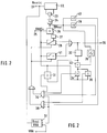
- Part of the control unit 9 is the embodiment of FIG. 2 shown in the form of a block diagram, only the arrangement for forming a VASR signal being shown here.
- the motor speed N mot is fed to a terminal 21 and is led to a shift register 22 with, for example, 8 memory locations.
- the eight most recently measured N mot values are stored here.
- a subtractor 23 forms N mot (n) - N mot (n-8).
- This value is divided by 8 in a divider 24.
- the result is the slope of the engine speed curve:
- the VABS (n) to which the signal DN mot / K is added in the combined adder / divider 26, is fed to a terminal 25 (corresponds to line 7, for example).
- K is a constant and eg 60, so that the value DN mot / K results in km / h.
- the result of the addition is the value by which the wheel speed value VABS may increase as much as possible in the next measurement.
- This limit value is temporarily stored in a memory 27 and is available as a limit value for a limiter 28 during the next measurement. This means that provided that the limiter 28 is active, VABS (n) passes the limiter 28 unaffected as long as the new value VABS (n) is less than VASR (n-1) + DM mot / K, but if it is larger is limited to the limit value.
- the output signal of the limiter 28 forms the valid VASR value in the event that the limiter is active and is available at a terminal 29 for processing.
- the limiter 28 is effective when one of the following conditions is met: 1) (VABS (n) ⁇ VASR (n-1)) ⁇ DN mot > 0 ⁇ (VABS (n) ⁇ (VASR (N-1) + DN mot / K and the first gear is engaged. 2) (DN mot ⁇ 0) ⁇ (VABS (n) ⁇ VASR (n-1) + DN mot / K and 1st gear is engaged.
- Condition 1 is met by an AND gate 30: this emits a signal when a) a comparator 31 emits a signal (VABS (n) greater (or equal) than the variable VASR (n-1 ), b) VABS (n) greater (or equal) VASR (n-1) + DN mot / K is (memory 32, adder 33, comparator 34, divider 35), c) DN mot > 0 (comparator 36) and the first gear is engaged (divider / comparator 37 which divides N mot by the average rear axle speed V HA and emits a signal if this is greater than a predetermined size, for example 75).
- the second condition is met by an AND gate 38: this outputs an output signal when the sum at the output of the adder 33 (VASR (n-1) + DN mot / K is less than or equal to VABS (n) (comparator 39) and DN mot > 0 (comparator 40) and first gear is also engaged.
- VASR (n-1) + DN mot / K is less than or equal to VABS (n) (comparator 39) and DN mot > 0 (comparator 40) and first gear is also engaged.
- a signal at the output of one of the AND gates 30 and 38 activates the limiter 28 and blocks a block 41.
- the limiter 28 is blocked and the block 41 is transparent if none of the AND gates 30 and 38 provides an output signal.
- VABS (n) forms the ASR wheel speed signal, which is then available at terminal 29.
- VASR When changing the sign of DN mot , VASR jumps to BABS, whereby the jumping height corresponds to the accumulated difference. But you can only jump if: and
- the DN mot query preferably has a hysteresis.
Abstract
Description
Aufgrund von Einstreuungen, Bremsenquietschen, Impulsradzucken durch Differentialübersprechen, Antriebsstrangschwingungen werden bei Antriebsschlupfregelsystemen vermeintlich plausible Geschwindigkeiten sensiert, die nicht der tatsächlichen Geschwindigkeit der angetriebenen Räder eines Kraftfahrzeuges entsprechen. Die Mittlung der Radgeschwindigkeiten über mehrere Rechenzyklen und/oder eine konstante Anstiegsbegrenzung sind die bisher eingesetzten Methoden zur Unterdrückung dieser Fehlereinflüsse.Due to interference, brake squeal, pulse wheel twitching due to differential crosstalk, drive train vibrations, supposedly plausible speeds are sensed in traction control systems that do not correspond to the actual speed of the driven wheels of a motor vehicle. The averaging of the wheel speeds over several computing cycles and / or a constant rise limitation are the methods used so far to suppress these error influences.
Eine aus dem Motordrehzahlgradient berechnete Geschwindigkeitsdifferenz dient bei der Erfindung als variable und plausible Anstiegsbegrenzung einer herkömmlich berechneten Geschwindigkeit eines angetriebenen Rades, wie diese bei ABS und ASR gewonnen werden.A speed difference calculated from the engine speed gradient is used in the invention as a variable and plausible rise limitation of a conventionally calculated speed of a driven wheel, such as those obtained with ABS and ASR.
Die Anstiegsbegrenzung kann weiter variiert werden, in Abhängigkeit von
- a) dem eingelegten Gang bzw. gewählt Gang bei Automatikgetriebe
- b) dem Rad, welches schneller dreht. Diesem Rad wird eine berechenbare geringere Begrenzung zugeordnet, als dem anderen Rad.
- c) einem Kupplungssignal, das proportional zum Kupplungsweg ist.
- d) dem Kupplungsschalter
- a) the gear selected or gear selected for automatic transmission
- b) the wheel that turns faster. A predictable lower limit is assigned to this wheel than to the other wheel.
- c) a clutch signal that is proportional to the clutch travel.
- d) the clutch switch
Die Erkennung einer µ-Split-Fahrbahn und damit die Umschaltung auf "select high" - Regelmodus wird verbessert.The detection of a µ-split road and thus the switch to "select high" control mode is improved.
In Fig. 1 ist in Blockschaltbilddarstellung ein Ausführungsbeispiel einer kombinierten ABS/ASR-Anlage gezeigt. Vier den vier Rädern eines Kraftfahrzeugs zugeordnete Geschwindigkeitssensoren sind mit 1 bis 4 bezeichnet. Deren Signale werden einem ABS-Steuergerät 5 zugeführt, das aus diesen Signalen Bremsdrucksteuersignale für die Magnetventile 6 erzeugt. Das Steuergerät 5 erzeugt zur Bremsschlupfermittlung gefilterte Radgeschwindigkeitssignale, die eine konstante Anstiegsbegrenzung aufweisen, d.h. es ist eine maximale Steigung des Radgeschwindigkeitsanstiegs vorgegeben, die z.B. 50 g sein kann. Diese Radgeschwindigkeiten VABS links und VABS rechts der angetriebenen Räder werden auch über Leitungen 7 und 8 zum Steuergerät 9 für ein ASR gegeben. Außerdem ermittelt das Steuergerät 5 ein Refernzgeschwindigkeitssignal aus den Radgeschwindigkeitssignalen der nicht angetriebenen Räder, das über eine Leitung 10 dem Steuergerät 9 als Fahrzeuggeschwindigkeit für die Schlupfbildung im ASR-Fall zugeführt wird. Diese Geschwindigkeitssignale stehen immer bei einem fahrenden Fahrzeug an. Ein Motordrehzahlmesser 11 liefert die Motordrehzahl Nmot.1 shows an embodiment of a combined ABS / ASR system in block diagram representation. Four speed sensors assigned to the four wheels of a motor vehicle are designated 1 to 4. Their signals are fed to an
Teil des Steuergerätes 9 ist das in Form eines Blockschaltbildes dargestellte Ausführungsbeispiel der Fig. 2, wobei hier nur die Anordnung zur Bildung eines VASR-Signales dargestellt ist.Part of the
An einer Klemme 21 wird die Motordrehzahl Nmot zugeführt, die zu einem Schieberegister 22 mit z.B. 8 Speicherplätzen geführt wird. Hierin sind jeweils die acht zuletzt gemessenen Nmot-Werte gespeichert. Ein Subtrahierglied 23 bildet
![]()
The motor speed N mot is fed to a terminal 21 and is led to a
![]()
Dieser Wert wird in einem Dividierer 24 durch 8 dividiert. Das Ergebnis ist die Steigung des Motordrehzahlverlaufs:
An einer Klemme 25 (entspricht z.B. Leitung 7) wird das VABS(n) zugeführt, zu dem im kombinierten Addierer/Dividierer 26 das Signal DNmot/K addiert wird. K ist eine Konstante und z.B. 60, so daß sich der Wert DNmot/K in km/h ergibt.This value is divided by 8 in a
The VABS (n), to which the signal DN mot / K is added in the combined adder /
Das Ergebnis der Addition ist der Wert, um den sich der Radgeschwindigkeitswert VABS bei der nächsten Messung maximal erhöhen darf. Dieser Begrenzungswert ist jeweils in einem Speicher 27 zwischengespeichert und steht bei der nächsten Messung als Begrenzungswert für einen Begrenzer 28 zur Verfügung. Dies bedeutet, daß unter der Voraussetzung, daß der Begrenzer 28 wirksam ist, VABS(n) den Begrenzer 28 unbeeinflußt passiert, solange der neue Wert VABS(n) kleiner VASR(n-1) + DMmot/K ist, jedoch wenn er größer ist auf den Begrenzungswert begrenzt wird. Das Ausgangssignal des Begrenzers 28 bildet im Falle, daß der Begrenzer wirksam ist, den gültigen VASR-Wert und steht an einer Klemme 29 zur Verarbeitung an. Der Begrenzer 28 ist wirksam, wenn eine der folgenden Bedingungen erfüllt sind:
![]()
![]()
![]()
The result of the addition is the value by which the wheel speed value VABS may increase as much as possible in the next measurement. This limit value is temporarily stored in a
![]()
![]()
![]()
Die Bedingung 1 wird durch ein Und-Gatter 30 erfüllt: Dieses gibt ein Signal ab, wenn a) ein Vergleicher 31 ein Signal abgibt (VABS(n) größer (oder gleich) als die in einem Zwischenspeicher 32 abgelegte Größe VASR (n-1), b) VABS(n) größer (oder gleich) VASR(n-1) + DNmot/K ist (Speicher 32, Addierer 33, Vergleicher 34, Dividierer 35), c) DNmot > 0 ist (Vergleicher 36) und der erste Gang eingelegt ist (Dividierer/Vergleicher 37, der Nmot durch die mittlere Hinterachsgeschwindigkeit VHA dividiert und ein Signal abgibt, wenn diese größer als eine vorgegebene Größe, z.B. 75 ist).
Die zweite Bedingung wird durch ein Und-Gatter 38 erfüllt: Dieses gibt ein Ausgangssignal ab, wenn die Summe am Ausgang des Addierers 33 (VASR(n-1) + DNmot/K kleiner oder gleich VABS(n) ist (Vergleicher 39) und DNmot > 0 ist (Vergleicher 40) ist und ebenfalls der erste Gang eingelegt ist.The second condition is met by an AND gate 38: this outputs an output signal when the sum at the output of the adder 33 (VASR (n-1) + DN mot / K is less than or equal to VABS (n) (comparator 39) and DN mot > 0 (comparator 40) and first gear is also engaged.
Ein Signal am Ausgang eines der Und-Gatter 30 und 38 aktiviert den Begrenzer 28 und blockiert einen Block 41. Andererseits wird der Begrenzer 28 blockiert und der Block 41 durchlässig, wenn keines der Und-Gatter 30 und 38 ein Ausgangssignal liefert. In diesem Fall bildet VABS(n) das ASR Radgeschwidigkeitssignal, das dann an Klemme 29 ansteht.A signal at the output of one of the
Beim Vorzeichenwechsel von DNmot springt VASR auf BABS, wobei die Springhöhe entsprechend der aufgelaufener Differenz ist. Es darf aber nur dann gesprungen werden, wenn:
und
Die DNmot - Abfrage weist vorzugsweise eine Hysterese auf.When changing the sign of DN mot , VASR jumps to BABS, whereby the jumping height corresponds to the accumulated difference. But you can only jump if:
and
The DN mot query preferably has a hysteresis.
Claims (11)
Applications Claiming Priority (2)
| Application Number | Priority Date | Filing Date | Title |
|---|---|---|---|
| DE4132490 | 1991-09-30 | ||
| DE4132490A DE4132490A1 (en) | 1991-09-30 | 1991-09-30 | DRIVE CONTROL SYSTEM |
Publications (3)
| Publication Number | Publication Date |
|---|---|
| EP0535349A2 true EP0535349A2 (en) | 1993-04-07 |
| EP0535349A3 EP0535349A3 (en) | 1993-07-28 |
| EP0535349B1 EP0535349B1 (en) | 1997-03-19 |
Family
ID=6441789
Family Applications (1)
| Application Number | Title | Priority Date | Filing Date |
|---|---|---|---|
| EP92114112A Expired - Lifetime EP0535349B1 (en) | 1991-09-30 | 1992-08-19 | Process for controlling drive slip |
Country Status (4)
| Country | Link |
|---|---|
| US (1) | US5366282A (en) |
| EP (1) | EP0535349B1 (en) |
| JP (1) | JPH06191389A (en) |
| DE (2) | DE4132490A1 (en) |
Families Citing this family (9)
| Publication number | Priority date | Publication date | Assignee | Title |
|---|---|---|---|---|
| DE4236004A1 (en) * | 1992-10-24 | 1994-04-28 | Bosch Gmbh Robert | Traction control system |
| DE19644231A1 (en) * | 1996-10-24 | 1998-04-30 | Teves Gmbh Alfred | Drive slip limiter for motor vehicle |
| DE19713252A1 (en) * | 1997-03-29 | 1998-10-01 | Bosch Gmbh Robert | Method and device for determining a variable describing the vehicle speed |
| DE10016814A1 (en) * | 1999-04-12 | 2001-02-08 | Continental Teves Ag & Co Ohg | Vehicle anti-slip system restricts the max torque developed at the powered wheel and/or the rotary speed difference to maintain traction and vehicle stability without damage to the axle differential |
| DE19934376A1 (en) * | 1999-07-22 | 2001-01-25 | Wabco Gmbh & Co Ohg | Traction control method |
| EP1125783B1 (en) * | 2000-02-19 | 2003-07-02 | Robert Bosch Gmbh | Method for controlling an automatic transmission |
| DE102011100814A1 (en) * | 2011-05-06 | 2012-11-08 | Audi Ag | Device for traction control for a vehicle with electromotive vehicle drive |
| US11154380B2 (en) | 2017-10-26 | 2021-10-26 | King Abdulaziz University | Dental restoration scalpel |
| DE102020115234A1 (en) | 2020-06-09 | 2021-12-09 | Audi Aktiengesellschaft | Guided rule exit with ASR implemented as a distributed function |
Citations (4)
| Publication number | Priority date | Publication date | Assignee | Title |
|---|---|---|---|---|
| DE2257658A1 (en) * | 1972-11-24 | 1974-05-30 | Kloeckner Humboldt Deutz Ag | DEVICE FOR REGULATING THE FUEL SUPPLY TO A COMBUSTION ENGINE FOR DRIVING A RAILWAY VEHICLE |
| JPS5715051A (en) * | 1980-07-01 | 1982-01-26 | Akebono Brake Ind Co Ltd | Method and apparatus for detecting condition |
| DE3709157A1 (en) * | 1986-03-20 | 1987-10-01 | Akebono Brake Ind | BRAKE CONTROL SYSTEM |
| DE3829903A1 (en) * | 1987-09-04 | 1989-03-23 | Nissan Motor | ANTI-LOCK BRAKE CONTROL SYSTEM FOR A MOTOR VEHICLE |
Family Cites Families (13)
| Publication number | Priority date | Publication date | Assignee | Title |
|---|---|---|---|---|
| AT292474B (en) * | 1968-03-25 | 1971-08-25 | Daimler Benz Ag | Device for preventing driven vehicle wheels from spinning, in particular for motor vehicles |
| US4419654A (en) * | 1981-07-17 | 1983-12-06 | Dickey-John Corporation | Tractor data center |
| JPH0650071B2 (en) * | 1983-12-14 | 1994-06-29 | 日産自動車株式会社 | Vehicle driving force control device |
| US4765430A (en) * | 1985-10-24 | 1988-08-23 | Volkswagen Ag | Method and arrangement for propulsion regulation of an automobile |
| DE3644136C1 (en) * | 1986-12-23 | 1988-09-01 | Daimler Benz Ag | Device for regulating propulsion on motor vehicles |
| EP0294634B1 (en) * | 1987-06-11 | 1994-04-06 | Honda Giken Kogyo Kabushiki Kaisha | Driving wheel slip control system for vehicles |
| DE3728573C1 (en) * | 1987-08-27 | 1988-11-24 | Daimler Benz Ag | Device for regulating at least one variable influencing the drive torque of an internal combustion engine of a motor vehicle |
| JPS6467462A (en) * | 1987-09-05 | 1989-03-14 | Nissan Motor | Anti-skid controller |
| JPS6487844A (en) * | 1987-09-29 | 1989-03-31 | Toyota Motor Corp | Engine brake control device |
| JP2502633B2 (en) * | 1987-11-16 | 1996-05-29 | 日産自動車株式会社 | Vehicle drive force control device |
| JP2519960B2 (en) * | 1987-12-28 | 1996-07-31 | いすゞ自動車株式会社 | Vehicle traction control method |
| US5047940A (en) * | 1988-06-07 | 1991-09-10 | Mazda Motor Corporation | Power train control apparatus for a vehicle |
| JPH0257441A (en) * | 1988-08-20 | 1990-02-27 | Nissan Motor Co Ltd | Device for controlling shift point of automatic transmission |
-
1991
- 1991-09-30 DE DE4132490A patent/DE4132490A1/en not_active Withdrawn
-
1992
- 1992-08-19 US US07/932,337 patent/US5366282A/en not_active Expired - Fee Related
- 1992-08-19 EP EP92114112A patent/EP0535349B1/en not_active Expired - Lifetime
- 1992-08-19 DE DE59208224T patent/DE59208224D1/en not_active Expired - Fee Related
- 1992-09-30 JP JP4261939A patent/JPH06191389A/en active Pending
Patent Citations (4)
| Publication number | Priority date | Publication date | Assignee | Title |
|---|---|---|---|---|
| DE2257658A1 (en) * | 1972-11-24 | 1974-05-30 | Kloeckner Humboldt Deutz Ag | DEVICE FOR REGULATING THE FUEL SUPPLY TO A COMBUSTION ENGINE FOR DRIVING A RAILWAY VEHICLE |
| JPS5715051A (en) * | 1980-07-01 | 1982-01-26 | Akebono Brake Ind Co Ltd | Method and apparatus for detecting condition |
| DE3709157A1 (en) * | 1986-03-20 | 1987-10-01 | Akebono Brake Ind | BRAKE CONTROL SYSTEM |
| DE3829903A1 (en) * | 1987-09-04 | 1989-03-23 | Nissan Motor | ANTI-LOCK BRAKE CONTROL SYSTEM FOR A MOTOR VEHICLE |
Non-Patent Citations (1)
| Title |
|---|
| PATENT ABSTRACTS OF JAPAN vol. 6, no. 76 (M-128)(954) 13. Mai 1982 & JP-A-57 15 051 ( AKEBONO BRAKE KOGYO K.K. ) 26. Januar 1982 * |
Also Published As
| Publication number | Publication date |
|---|---|
| EP0535349A3 (en) | 1993-07-28 |
| JPH06191389A (en) | 1994-07-12 |
| DE59208224D1 (en) | 1997-04-24 |
| DE4132490A1 (en) | 1993-04-01 |
| US5366282A (en) | 1994-11-22 |
| EP0535349B1 (en) | 1997-03-19 |
Similar Documents
| Publication | Publication Date | Title |
|---|---|---|
| EP0495796B1 (en) | Antilock braking method and drive slip control method | |
| DE112004001278B4 (en) | Method and device for determining a motor vehicle acceleration | |
| DE3606797C2 (en) | Device and method for controlling, in particular for limiting, the driving speed of a road vehicle | |
| EP0391943B1 (en) | Process for correcting the speed of rotation of vehicle wheels determined by wheel sensors | |
| EP0111636B1 (en) | Process and device for the detection of the weight of a vehicle | |
| DE4011214C2 (en) | Control arrangement for distributing the drive torque of an engine to the wheels of a motor vehicle | |
| DE3705983A1 (en) | Device for monitoring the utilisation factor of the coefficient of road friction prevailing in the braking and/or acceleration of a motor vehicle | |
| DE3345730C2 (en) | Arrangement for generating a vehicle reference speed | |
| DE60222499T2 (en) | Apparatus and method for evaluating road surface gradients and program for evaluating gradients | |
| WO2003040652A1 (en) | Method and device for determining the geometric vehicle inclination of a motor vehicle | |
| DE4228413A1 (en) | Motor vehicle weight calculation - dividing difference between drive forces, measured at spaced times, by difference between accelerations measured at corresponding times, to form quotient | |
| DE102008029803B4 (en) | Road surface condition estimation device | |
| DE19722116C2 (en) | Anti-lock brake control system for motor vehicles and associated brake force control method | |
| DE4428351A1 (en) | Method for estimating the maneouvering state of a vehicle and method for controlling the operational properties of vehicle | |
| DE4111515A1 (en) | ANTIBLOCKING BRAKE SYSTEM FOR A VEHICLE | |
| EP0389497A1 (en) | Drive slip regulating system. | |
| EP0142633B1 (en) | Device for the determination of road inclination | |
| EP0535349B1 (en) | Process for controlling drive slip | |
| DE4338587C2 (en) | Method for assessing the gripping behavior of a road surface relative to the wheels of a motor vehicle traveling over it | |
| EP0705177B1 (en) | Traction-control unit | |
| DE3637594C2 (en) | ||
| DE19810213A1 (en) | Method and device for generating a signal representative of a motor vehicle running conditions | |
| DE69629539T2 (en) | Control unit for an anti-lock braking system | |
| DE19537791C2 (en) | Method and device for determining the driving speed of a motor vehicle | |
| DE60314727T2 (en) | A method and computer for estimating the friction between tires and the road |
Legal Events
| Date | Code | Title | Description |
|---|---|---|---|
| PUAI | Public reference made under article 153(3) epc to a published international application that has entered the european phase |
Free format text: ORIGINAL CODE: 0009012 |
|
| AK | Designated contracting states |
Kind code of ref document: A2 Designated state(s): DE GB SE |
|
| PUAL | Search report despatched |
Free format text: ORIGINAL CODE: 0009013 |
|
| AK | Designated contracting states |
Kind code of ref document: A3 Designated state(s): DE GB SE |
|
| 17P | Request for examination filed |
Effective date: 19940124 |
|
| 17Q | First examination report despatched |
Effective date: 19950905 |
|
| GRAG | Despatch of communication of intention to grant |
Free format text: ORIGINAL CODE: EPIDOS AGRA |
|
| GRAH | Despatch of communication of intention to grant a patent |
Free format text: ORIGINAL CODE: EPIDOS IGRA |
|
| GRAH | Despatch of communication of intention to grant a patent |
Free format text: ORIGINAL CODE: EPIDOS IGRA |
|
| GRAA | (expected) grant |
Free format text: ORIGINAL CODE: 0009210 |
|
| AK | Designated contracting states |
Kind code of ref document: B1 Designated state(s): DE GB SE |
|
| REF | Corresponds to: |
Ref document number: 59208224 Country of ref document: DE Date of ref document: 19970424 |
|
| GBT | Gb: translation of ep patent filed (gb section 77(6)(a)/1977) |
Effective date: 19970521 |
|
| PLBE | No opposition filed within time limit |
Free format text: ORIGINAL CODE: 0009261 |
|
| STAA | Information on the status of an ep patent application or granted ep patent |
Free format text: STATUS: NO OPPOSITION FILED WITHIN TIME LIMIT |
|
| 26N | No opposition filed | ||
| REG | Reference to a national code |
Ref country code: GB Ref legal event code: IF02 |
|
| PGFP | Annual fee paid to national office [announced via postgrant information from national office to epo] |
Ref country code: SE Payment date: 20020822 Year of fee payment: 11 |
|
| PGFP | Annual fee paid to national office [announced via postgrant information from national office to epo] |
Ref country code: GB Payment date: 20030729 Year of fee payment: 12 |
|
| PG25 | Lapsed in a contracting state [announced via postgrant information from national office to epo] |
Ref country code: SE Free format text: LAPSE BECAUSE OF NON-PAYMENT OF DUE FEES Effective date: 20030820 |
|
| EUG | Se: european patent has lapsed | ||
| PG25 | Lapsed in a contracting state [announced via postgrant information from national office to epo] |
Ref country code: GB Free format text: LAPSE BECAUSE OF NON-PAYMENT OF DUE FEES Effective date: 20040819 |
|
| GBPC | Gb: european patent ceased through non-payment of renewal fee |
Effective date: 20040819 |
|
| PGFP | Annual fee paid to national office [announced via postgrant information from national office to epo] |
Ref country code: DE Payment date: 20081024 Year of fee payment: 17 |
|
| PG25 | Lapsed in a contracting state [announced via postgrant information from national office to epo] |
Ref country code: DE Free format text: LAPSE BECAUSE OF NON-PAYMENT OF DUE FEES Effective date: 20100302 |