EP0535247A1 - Pipe joint member - Google Patents
Pipe joint member Download PDFInfo
- Publication number
- EP0535247A1 EP0535247A1 EP92908284A EP92908284A EP0535247A1 EP 0535247 A1 EP0535247 A1 EP 0535247A1 EP 92908284 A EP92908284 A EP 92908284A EP 92908284 A EP92908284 A EP 92908284A EP 0535247 A1 EP0535247 A1 EP 0535247A1
- Authority
- EP
- European Patent Office
- Prior art keywords
- pipe
- receiving member
- conduit
- composing
- pipe connecting
- Prior art date
- Legal status (The legal status is an assumption and is not a legal conclusion. Google has not performed a legal analysis and makes no representation as to the accuracy of the status listed.)
- Granted
Links
Images


Classifications
-
- B—PERFORMING OPERATIONS; TRANSPORTING
- B29—WORKING OF PLASTICS; WORKING OF SUBSTANCES IN A PLASTIC STATE IN GENERAL
- B29C—SHAPING OR JOINING OF PLASTICS; SHAPING OF MATERIAL IN A PLASTIC STATE, NOT OTHERWISE PROVIDED FOR; AFTER-TREATMENT OF THE SHAPED PRODUCTS, e.g. REPAIRING
- B29C65/00—Joining or sealing of preformed parts, e.g. welding of plastics materials; Apparatus therefor
- B29C65/02—Joining or sealing of preformed parts, e.g. welding of plastics materials; Apparatus therefor by heating, with or without pressure
- B29C65/18—Joining or sealing of preformed parts, e.g. welding of plastics materials; Apparatus therefor by heating, with or without pressure using heated tools
- B29C65/20—Joining or sealing of preformed parts, e.g. welding of plastics materials; Apparatus therefor by heating, with or without pressure using heated tools with direct contact, e.g. using "mirror"
-
- F—MECHANICAL ENGINEERING; LIGHTING; HEATING; WEAPONS; BLASTING
- F16—ENGINEERING ELEMENTS AND UNITS; GENERAL MEASURES FOR PRODUCING AND MAINTAINING EFFECTIVE FUNCTIONING OF MACHINES OR INSTALLATIONS; THERMAL INSULATION IN GENERAL
- F16L—PIPES; JOINTS OR FITTINGS FOR PIPES; SUPPORTS FOR PIPES, CABLES OR PROTECTIVE TUBING; MEANS FOR THERMAL INSULATION IN GENERAL
- F16L15/00—Screw-threaded joints; Forms of screw-threads for such joints
- F16L15/04—Screw-threaded joints; Forms of screw-threads for such joints with additional sealings
-
- B—PERFORMING OPERATIONS; TRANSPORTING
- B29—WORKING OF PLASTICS; WORKING OF SUBSTANCES IN A PLASTIC STATE IN GENERAL
- B29C—SHAPING OR JOINING OF PLASTICS; SHAPING OF MATERIAL IN A PLASTIC STATE, NOT OTHERWISE PROVIDED FOR; AFTER-TREATMENT OF THE SHAPED PRODUCTS, e.g. REPAIRING
- B29C65/00—Joining or sealing of preformed parts, e.g. welding of plastics materials; Apparatus therefor
- B29C65/02—Joining or sealing of preformed parts, e.g. welding of plastics materials; Apparatus therefor by heating, with or without pressure
- B29C65/34—Joining or sealing of preformed parts, e.g. welding of plastics materials; Apparatus therefor by heating, with or without pressure using heated elements which remain in the joint, e.g. "verlorenes Schweisselement"
- B29C65/3404—Joining or sealing of preformed parts, e.g. welding of plastics materials; Apparatus therefor by heating, with or without pressure using heated elements which remain in the joint, e.g. "verlorenes Schweisselement" characterised by the type of heated elements which remain in the joint
- B29C65/342—Joining or sealing of preformed parts, e.g. welding of plastics materials; Apparatus therefor by heating, with or without pressure using heated elements which remain in the joint, e.g. "verlorenes Schweisselement" characterised by the type of heated elements which remain in the joint comprising at least a single wire, e.g. in the form of a winding
- B29C65/3432—Joining or sealing of preformed parts, e.g. welding of plastics materials; Apparatus therefor by heating, with or without pressure using heated elements which remain in the joint, e.g. "verlorenes Schweisselement" characterised by the type of heated elements which remain in the joint comprising at least a single wire, e.g. in the form of a winding comprising several wires, e.g. in the form of several independent windings
-
- B—PERFORMING OPERATIONS; TRANSPORTING
- B29—WORKING OF PLASTICS; WORKING OF SUBSTANCES IN A PLASTIC STATE IN GENERAL
- B29C—SHAPING OR JOINING OF PLASTICS; SHAPING OF MATERIAL IN A PLASTIC STATE, NOT OTHERWISE PROVIDED FOR; AFTER-TREATMENT OF THE SHAPED PRODUCTS, e.g. REPAIRING
- B29C65/00—Joining or sealing of preformed parts, e.g. welding of plastics materials; Apparatus therefor
- B29C65/02—Joining or sealing of preformed parts, e.g. welding of plastics materials; Apparatus therefor by heating, with or without pressure
- B29C65/34—Joining or sealing of preformed parts, e.g. welding of plastics materials; Apparatus therefor by heating, with or without pressure using heated elements which remain in the joint, e.g. "verlorenes Schweisselement"
- B29C65/3468—Joining or sealing of preformed parts, e.g. welding of plastics materials; Apparatus therefor by heating, with or without pressure using heated elements which remain in the joint, e.g. "verlorenes Schweisselement" characterised by the means for supplying heat to said heated elements which remain in the join, e.g. special electrical connectors of windings
-
- B—PERFORMING OPERATIONS; TRANSPORTING
- B29—WORKING OF PLASTICS; WORKING OF SUBSTANCES IN A PLASTIC STATE IN GENERAL
- B29C—SHAPING OR JOINING OF PLASTICS; SHAPING OF MATERIAL IN A PLASTIC STATE, NOT OTHERWISE PROVIDED FOR; AFTER-TREATMENT OF THE SHAPED PRODUCTS, e.g. REPAIRING
- B29C65/00—Joining or sealing of preformed parts, e.g. welding of plastics materials; Apparatus therefor
- B29C65/02—Joining or sealing of preformed parts, e.g. welding of plastics materials; Apparatus therefor by heating, with or without pressure
- B29C65/34—Joining or sealing of preformed parts, e.g. welding of plastics materials; Apparatus therefor by heating, with or without pressure using heated elements which remain in the joint, e.g. "verlorenes Schweisselement"
- B29C65/3472—Joining or sealing of preformed parts, e.g. welding of plastics materials; Apparatus therefor by heating, with or without pressure using heated elements which remain in the joint, e.g. "verlorenes Schweisselement" characterised by the composition of the heated elements which remain in the joint
- B29C65/3476—Joining or sealing of preformed parts, e.g. welding of plastics materials; Apparatus therefor by heating, with or without pressure using heated elements which remain in the joint, e.g. "verlorenes Schweisselement" characterised by the composition of the heated elements which remain in the joint being metallic
-
- B—PERFORMING OPERATIONS; TRANSPORTING
- B29—WORKING OF PLASTICS; WORKING OF SUBSTANCES IN A PLASTIC STATE IN GENERAL
- B29C—SHAPING OR JOINING OF PLASTICS; SHAPING OF MATERIAL IN A PLASTIC STATE, NOT OTHERWISE PROVIDED FOR; AFTER-TREATMENT OF THE SHAPED PRODUCTS, e.g. REPAIRING
- B29C65/00—Joining or sealing of preformed parts, e.g. welding of plastics materials; Apparatus therefor
- B29C65/72—Joining or sealing of preformed parts, e.g. welding of plastics materials; Apparatus therefor by combined operations or combined techniques, e.g. welding and stitching
-
- B—PERFORMING OPERATIONS; TRANSPORTING
- B29—WORKING OF PLASTICS; WORKING OF SUBSTANCES IN A PLASTIC STATE IN GENERAL
- B29C—SHAPING OR JOINING OF PLASTICS; SHAPING OF MATERIAL IN A PLASTIC STATE, NOT OTHERWISE PROVIDED FOR; AFTER-TREATMENT OF THE SHAPED PRODUCTS, e.g. REPAIRING
- B29C66/00—General aspects of processes or apparatus for joining preformed parts
- B29C66/01—General aspects dealing with the joint area or with the area to be joined
- B29C66/05—Particular design of joint configurations
- B29C66/10—Particular design of joint configurations particular design of the joint cross-sections
- B29C66/11—Joint cross-sections comprising a single joint-segment, i.e. one of the parts to be joined comprising a single joint-segment in the joint cross-section
- B29C66/112—Single lapped joints
- B29C66/1122—Single lap to lap joints, i.e. overlap joints
-
- B—PERFORMING OPERATIONS; TRANSPORTING
- B29—WORKING OF PLASTICS; WORKING OF SUBSTANCES IN A PLASTIC STATE IN GENERAL
- B29C—SHAPING OR JOINING OF PLASTICS; SHAPING OF MATERIAL IN A PLASTIC STATE, NOT OTHERWISE PROVIDED FOR; AFTER-TREATMENT OF THE SHAPED PRODUCTS, e.g. REPAIRING
- B29C66/00—General aspects of processes or apparatus for joining preformed parts
- B29C66/01—General aspects dealing with the joint area or with the area to be joined
- B29C66/05—Particular design of joint configurations
- B29C66/10—Particular design of joint configurations particular design of the joint cross-sections
- B29C66/12—Joint cross-sections combining only two joint-segments; Tongue and groove joints; Tenon and mortise joints; Stepped joint cross-sections
- B29C66/122—Joint cross-sections combining only two joint-segments, i.e. one of the parts to be joined comprising only two joint-segments in the joint cross-section
- B29C66/1222—Joint cross-sections combining only two joint-segments, i.e. one of the parts to be joined comprising only two joint-segments in the joint cross-section comprising at least a lapped joint-segment
-
- B—PERFORMING OPERATIONS; TRANSPORTING
- B29—WORKING OF PLASTICS; WORKING OF SUBSTANCES IN A PLASTIC STATE IN GENERAL
- B29C—SHAPING OR JOINING OF PLASTICS; SHAPING OF MATERIAL IN A PLASTIC STATE, NOT OTHERWISE PROVIDED FOR; AFTER-TREATMENT OF THE SHAPED PRODUCTS, e.g. REPAIRING
- B29C66/00—General aspects of processes or apparatus for joining preformed parts
- B29C66/01—General aspects dealing with the joint area or with the area to be joined
- B29C66/05—Particular design of joint configurations
- B29C66/10—Particular design of joint configurations particular design of the joint cross-sections
- B29C66/12—Joint cross-sections combining only two joint-segments; Tongue and groove joints; Tenon and mortise joints; Stepped joint cross-sections
- B29C66/122—Joint cross-sections combining only two joint-segments, i.e. one of the parts to be joined comprising only two joint-segments in the joint cross-section
- B29C66/1224—Joint cross-sections combining only two joint-segments, i.e. one of the parts to be joined comprising only two joint-segments in the joint cross-section comprising at least a butt joint-segment
-
- B—PERFORMING OPERATIONS; TRANSPORTING
- B29—WORKING OF PLASTICS; WORKING OF SUBSTANCES IN A PLASTIC STATE IN GENERAL
- B29C—SHAPING OR JOINING OF PLASTICS; SHAPING OF MATERIAL IN A PLASTIC STATE, NOT OTHERWISE PROVIDED FOR; AFTER-TREATMENT OF THE SHAPED PRODUCTS, e.g. REPAIRING
- B29C66/00—General aspects of processes or apparatus for joining preformed parts
- B29C66/01—General aspects dealing with the joint area or with the area to be joined
- B29C66/05—Particular design of joint configurations
- B29C66/10—Particular design of joint configurations particular design of the joint cross-sections
- B29C66/12—Joint cross-sections combining only two joint-segments; Tongue and groove joints; Tenon and mortise joints; Stepped joint cross-sections
- B29C66/122—Joint cross-sections combining only two joint-segments, i.e. one of the parts to be joined comprising only two joint-segments in the joint cross-section
- B29C66/1226—Joint cross-sections combining only two joint-segments, i.e. one of the parts to be joined comprising only two joint-segments in the joint cross-section comprising at least one bevelled joint-segment
-
- B—PERFORMING OPERATIONS; TRANSPORTING
- B29—WORKING OF PLASTICS; WORKING OF SUBSTANCES IN A PLASTIC STATE IN GENERAL
- B29C—SHAPING OR JOINING OF PLASTICS; SHAPING OF MATERIAL IN A PLASTIC STATE, NOT OTHERWISE PROVIDED FOR; AFTER-TREATMENT OF THE SHAPED PRODUCTS, e.g. REPAIRING
- B29C66/00—General aspects of processes or apparatus for joining preformed parts
- B29C66/50—General aspects of joining tubular articles; General aspects of joining long products, i.e. bars or profiled elements; General aspects of joining single elements to tubular articles, hollow articles or bars; General aspects of joining several hollow-preforms to form hollow or tubular articles
- B29C66/51—Joining tubular articles, profiled elements or bars; Joining single elements to tubular articles, hollow articles or bars; Joining several hollow-preforms to form hollow or tubular articles
- B29C66/52—Joining tubular articles, bars or profiled elements
- B29C66/522—Joining tubular articles
- B29C66/5221—Joining tubular articles for forming coaxial connections, i.e. the tubular articles to be joined forming a zero angle relative to each other
-
- B—PERFORMING OPERATIONS; TRANSPORTING
- B29—WORKING OF PLASTICS; WORKING OF SUBSTANCES IN A PLASTIC STATE IN GENERAL
- B29C—SHAPING OR JOINING OF PLASTICS; SHAPING OF MATERIAL IN A PLASTIC STATE, NOT OTHERWISE PROVIDED FOR; AFTER-TREATMENT OF THE SHAPED PRODUCTS, e.g. REPAIRING
- B29C66/00—General aspects of processes or apparatus for joining preformed parts
- B29C66/50—General aspects of joining tubular articles; General aspects of joining long products, i.e. bars or profiled elements; General aspects of joining single elements to tubular articles, hollow articles or bars; General aspects of joining several hollow-preforms to form hollow or tubular articles
- B29C66/51—Joining tubular articles, profiled elements or bars; Joining single elements to tubular articles, hollow articles or bars; Joining several hollow-preforms to form hollow or tubular articles
- B29C66/52—Joining tubular articles, bars or profiled elements
- B29C66/522—Joining tubular articles
- B29C66/5223—Joining tubular articles for forming corner connections or elbows, e.g. for making V-shaped pieces
- B29C66/52231—Joining tubular articles for forming corner connections or elbows, e.g. for making V-shaped pieces with a right angle, e.g. for making L-shaped pieces
-
- B—PERFORMING OPERATIONS; TRANSPORTING
- B29—WORKING OF PLASTICS; WORKING OF SUBSTANCES IN A PLASTIC STATE IN GENERAL
- B29C—SHAPING OR JOINING OF PLASTICS; SHAPING OF MATERIAL IN A PLASTIC STATE, NOT OTHERWISE PROVIDED FOR; AFTER-TREATMENT OF THE SHAPED PRODUCTS, e.g. REPAIRING
- B29C66/00—General aspects of processes or apparatus for joining preformed parts
- B29C66/50—General aspects of joining tubular articles; General aspects of joining long products, i.e. bars or profiled elements; General aspects of joining single elements to tubular articles, hollow articles or bars; General aspects of joining several hollow-preforms to form hollow or tubular articles
- B29C66/51—Joining tubular articles, profiled elements or bars; Joining single elements to tubular articles, hollow articles or bars; Joining several hollow-preforms to form hollow or tubular articles
- B29C66/52—Joining tubular articles, bars or profiled elements
- B29C66/522—Joining tubular articles
- B29C66/5224—Joining tubular articles for forming fork-shaped connections, e.g. for making Y-shaped pieces
- B29C66/52241—Joining tubular articles for forming fork-shaped connections, e.g. for making Y-shaped pieces with two right angles, e.g. for making T-shaped pieces
-
- B—PERFORMING OPERATIONS; TRANSPORTING
- B29—WORKING OF PLASTICS; WORKING OF SUBSTANCES IN A PLASTIC STATE IN GENERAL
- B29C—SHAPING OR JOINING OF PLASTICS; SHAPING OF MATERIAL IN A PLASTIC STATE, NOT OTHERWISE PROVIDED FOR; AFTER-TREATMENT OF THE SHAPED PRODUCTS, e.g. REPAIRING
- B29C66/00—General aspects of processes or apparatus for joining preformed parts
- B29C66/50—General aspects of joining tubular articles; General aspects of joining long products, i.e. bars or profiled elements; General aspects of joining single elements to tubular articles, hollow articles or bars; General aspects of joining several hollow-preforms to form hollow or tubular articles
- B29C66/51—Joining tubular articles, profiled elements or bars; Joining single elements to tubular articles, hollow articles or bars; Joining several hollow-preforms to form hollow or tubular articles
- B29C66/52—Joining tubular articles, bars or profiled elements
- B29C66/522—Joining tubular articles
- B29C66/5225—Joining tubular articles for forming cross-shaped connections, e.g. for making X-shaped pieces
- B29C66/52251—Joining tubular articles for forming cross-shaped connections, e.g. for making X-shaped pieces with four right angles, e.g. for making +-shaped pieces
-
- B—PERFORMING OPERATIONS; TRANSPORTING
- B29—WORKING OF PLASTICS; WORKING OF SUBSTANCES IN A PLASTIC STATE IN GENERAL
- B29C—SHAPING OR JOINING OF PLASTICS; SHAPING OF MATERIAL IN A PLASTIC STATE, NOT OTHERWISE PROVIDED FOR; AFTER-TREATMENT OF THE SHAPED PRODUCTS, e.g. REPAIRING
- B29C66/00—General aspects of processes or apparatus for joining preformed parts
- B29C66/50—General aspects of joining tubular articles; General aspects of joining long products, i.e. bars or profiled elements; General aspects of joining single elements to tubular articles, hollow articles or bars; General aspects of joining several hollow-preforms to form hollow or tubular articles
- B29C66/51—Joining tubular articles, profiled elements or bars; Joining single elements to tubular articles, hollow articles or bars; Joining several hollow-preforms to form hollow or tubular articles
- B29C66/52—Joining tubular articles, bars or profiled elements
- B29C66/522—Joining tubular articles
- B29C66/5229—Joining tubular articles involving the use of a socket
- B29C66/52291—Joining tubular articles involving the use of a socket said socket comprising a stop
- B29C66/52292—Joining tubular articles involving the use of a socket said socket comprising a stop said stop being internal
-
- B—PERFORMING OPERATIONS; TRANSPORTING
- B29—WORKING OF PLASTICS; WORKING OF SUBSTANCES IN A PLASTIC STATE IN GENERAL
- B29C—SHAPING OR JOINING OF PLASTICS; SHAPING OF MATERIAL IN A PLASTIC STATE, NOT OTHERWISE PROVIDED FOR; AFTER-TREATMENT OF THE SHAPED PRODUCTS, e.g. REPAIRING
- B29C66/00—General aspects of processes or apparatus for joining preformed parts
- B29C66/50—General aspects of joining tubular articles; General aspects of joining long products, i.e. bars or profiled elements; General aspects of joining single elements to tubular articles, hollow articles or bars; General aspects of joining several hollow-preforms to form hollow or tubular articles
- B29C66/51—Joining tubular articles, profiled elements or bars; Joining single elements to tubular articles, hollow articles or bars; Joining several hollow-preforms to form hollow or tubular articles
- B29C66/52—Joining tubular articles, bars or profiled elements
- B29C66/522—Joining tubular articles
- B29C66/5229—Joining tubular articles involving the use of a socket
- B29C66/52297—Joining tubular articles involving the use of a socket said socket comprising slip-off prevention means
-
- B—PERFORMING OPERATIONS; TRANSPORTING
- B29—WORKING OF PLASTICS; WORKING OF SUBSTANCES IN A PLASTIC STATE IN GENERAL
- B29C—SHAPING OR JOINING OF PLASTICS; SHAPING OF MATERIAL IN A PLASTIC STATE, NOT OTHERWISE PROVIDED FOR; AFTER-TREATMENT OF THE SHAPED PRODUCTS, e.g. REPAIRING
- B29C66/00—General aspects of processes or apparatus for joining preformed parts
- B29C66/50—General aspects of joining tubular articles; General aspects of joining long products, i.e. bars or profiled elements; General aspects of joining single elements to tubular articles, hollow articles or bars; General aspects of joining several hollow-preforms to form hollow or tubular articles
- B29C66/51—Joining tubular articles, profiled elements or bars; Joining single elements to tubular articles, hollow articles or bars; Joining several hollow-preforms to form hollow or tubular articles
- B29C66/52—Joining tubular articles, bars or profiled elements
- B29C66/522—Joining tubular articles
- B29C66/5229—Joining tubular articles involving the use of a socket
- B29C66/52298—Joining tubular articles involving the use of a socket said socket being composed by several elements
-
- B—PERFORMING OPERATIONS; TRANSPORTING
- B29—WORKING OF PLASTICS; WORKING OF SUBSTANCES IN A PLASTIC STATE IN GENERAL
- B29C—SHAPING OR JOINING OF PLASTICS; SHAPING OF MATERIAL IN A PLASTIC STATE, NOT OTHERWISE PROVIDED FOR; AFTER-TREATMENT OF THE SHAPED PRODUCTS, e.g. REPAIRING
- B29C66/00—General aspects of processes or apparatus for joining preformed parts
- B29C66/50—General aspects of joining tubular articles; General aspects of joining long products, i.e. bars or profiled elements; General aspects of joining single elements to tubular articles, hollow articles or bars; General aspects of joining several hollow-preforms to form hollow or tubular articles
- B29C66/51—Joining tubular articles, profiled elements or bars; Joining single elements to tubular articles, hollow articles or bars; Joining several hollow-preforms to form hollow or tubular articles
- B29C66/53—Joining single elements to tubular articles, hollow articles or bars
- B29C66/534—Joining single elements to open ends of tubular or hollow articles or to the ends of bars
- B29C66/5344—Joining single elements to open ends of tubular or hollow articles or to the ends of bars said single elements being substantially annular, i.e. of finite length, e.g. joining flanges to tube ends
-
- B—PERFORMING OPERATIONS; TRANSPORTING
- B29—WORKING OF PLASTICS; WORKING OF SUBSTANCES IN A PLASTIC STATE IN GENERAL
- B29C—SHAPING OR JOINING OF PLASTICS; SHAPING OF MATERIAL IN A PLASTIC STATE, NOT OTHERWISE PROVIDED FOR; AFTER-TREATMENT OF THE SHAPED PRODUCTS, e.g. REPAIRING
- B29C66/00—General aspects of processes or apparatus for joining preformed parts
- B29C66/80—General aspects of machine operations or constructions and parts thereof
- B29C66/84—Specific machine types or machines suitable for specific applications
- B29C66/841—Machines or tools adaptable for making articles of different dimensions or shapes or for making joints of different dimensions
- B29C66/8414—Machines or tools adaptable for making articles of different dimensions or shapes or for making joints of different dimensions of different diameter
-
- B—PERFORMING OPERATIONS; TRANSPORTING
- B29—WORKING OF PLASTICS; WORKING OF SUBSTANCES IN A PLASTIC STATE IN GENERAL
- B29C—SHAPING OR JOINING OF PLASTICS; SHAPING OF MATERIAL IN A PLASTIC STATE, NOT OTHERWISE PROVIDED FOR; AFTER-TREATMENT OF THE SHAPED PRODUCTS, e.g. REPAIRING
- B29C66/00—General aspects of processes or apparatus for joining preformed parts
- B29C66/90—Measuring or controlling the joining process
- B29C66/97—Checking completion of joining or correct joining by using indications on at least one of the joined parts
- B29C66/976—Checking completion of joining or correct joining by using indications on at least one of the joined parts by the use of an indicator pin, e.g. being integral with one of the parts to be joined
-
- F—MECHANICAL ENGINEERING; LIGHTING; HEATING; WEAPONS; BLASTING
- F16—ENGINEERING ELEMENTS AND UNITS; GENERAL MEASURES FOR PRODUCING AND MAINTAINING EFFECTIVE FUNCTIONING OF MACHINES OR INSTALLATIONS; THERMAL INSULATION IN GENERAL
- F16L—PIPES; JOINTS OR FITTINGS FOR PIPES; SUPPORTS FOR PIPES, CABLES OR PROTECTIVE TUBING; MEANS FOR THERMAL INSULATION IN GENERAL
- F16L47/00—Connecting arrangements or other fittings specially adapted to be made of plastics or to be used with pipes made of plastics
- F16L47/02—Welded joints; Adhesive joints
- F16L47/03—Welded joints with an electrical resistance incorporated in the joint
-
- B—PERFORMING OPERATIONS; TRANSPORTING
- B29—WORKING OF PLASTICS; WORKING OF SUBSTANCES IN A PLASTIC STATE IN GENERAL
- B29C—SHAPING OR JOINING OF PLASTICS; SHAPING OF MATERIAL IN A PLASTIC STATE, NOT OTHERWISE PROVIDED FOR; AFTER-TREATMENT OF THE SHAPED PRODUCTS, e.g. REPAIRING
- B29C65/00—Joining or sealing of preformed parts, e.g. welding of plastics materials; Apparatus therefor
- B29C65/02—Joining or sealing of preformed parts, e.g. welding of plastics materials; Apparatus therefor by heating, with or without pressure
- B29C65/34—Joining or sealing of preformed parts, e.g. welding of plastics materials; Apparatus therefor by heating, with or without pressure using heated elements which remain in the joint, e.g. "verlorenes Schweisselement"
- B29C65/3404—Joining or sealing of preformed parts, e.g. welding of plastics materials; Apparatus therefor by heating, with or without pressure using heated elements which remain in the joint, e.g. "verlorenes Schweisselement" characterised by the type of heated elements which remain in the joint
- B29C65/3464—Joining or sealing of preformed parts, e.g. welding of plastics materials; Apparatus therefor by heating, with or without pressure using heated elements which remain in the joint, e.g. "verlorenes Schweisselement" characterised by the type of heated elements which remain in the joint characterised by the cross-section of said heated elements which remain in the joint or by the cross-section of their coating, e.g. being triangular
-
- B—PERFORMING OPERATIONS; TRANSPORTING
- B29—WORKING OF PLASTICS; WORKING OF SUBSTANCES IN A PLASTIC STATE IN GENERAL
- B29C—SHAPING OR JOINING OF PLASTICS; SHAPING OF MATERIAL IN A PLASTIC STATE, NOT OTHERWISE PROVIDED FOR; AFTER-TREATMENT OF THE SHAPED PRODUCTS, e.g. REPAIRING
- B29C65/00—Joining or sealing of preformed parts, e.g. welding of plastics materials; Apparatus therefor
- B29C65/02—Joining or sealing of preformed parts, e.g. welding of plastics materials; Apparatus therefor by heating, with or without pressure
- B29C65/34—Joining or sealing of preformed parts, e.g. welding of plastics materials; Apparatus therefor by heating, with or without pressure using heated elements which remain in the joint, e.g. "verlorenes Schweisselement"
- B29C65/3472—Joining or sealing of preformed parts, e.g. welding of plastics materials; Apparatus therefor by heating, with or without pressure using heated elements which remain in the joint, e.g. "verlorenes Schweisselement" characterised by the composition of the heated elements which remain in the joint
- B29C65/3476—Joining or sealing of preformed parts, e.g. welding of plastics materials; Apparatus therefor by heating, with or without pressure using heated elements which remain in the joint, e.g. "verlorenes Schweisselement" characterised by the composition of the heated elements which remain in the joint being metallic
- B29C65/348—Joining or sealing of preformed parts, e.g. welding of plastics materials; Apparatus therefor by heating, with or without pressure using heated elements which remain in the joint, e.g. "verlorenes Schweisselement" characterised by the composition of the heated elements which remain in the joint being metallic with a polymer coating
-
- B—PERFORMING OPERATIONS; TRANSPORTING
- B29—WORKING OF PLASTICS; WORKING OF SUBSTANCES IN A PLASTIC STATE IN GENERAL
- B29C—SHAPING OR JOINING OF PLASTICS; SHAPING OF MATERIAL IN A PLASTIC STATE, NOT OTHERWISE PROVIDED FOR; AFTER-TREATMENT OF THE SHAPED PRODUCTS, e.g. REPAIRING
- B29C65/00—Joining or sealing of preformed parts, e.g. welding of plastics materials; Apparatus therefor
- B29C65/78—Means for handling the parts to be joined, e.g. for making containers or hollow articles, e.g. means for handling sheets, plates, web-like materials, tubular articles, hollow articles or elements to be joined therewith; Means for discharging the joined articles from the joining apparatus
- B29C65/7841—Holding or clamping means for handling purposes
-
- B—PERFORMING OPERATIONS; TRANSPORTING
- B29—WORKING OF PLASTICS; WORKING OF SUBSTANCES IN A PLASTIC STATE IN GENERAL
- B29C—SHAPING OR JOINING OF PLASTICS; SHAPING OF MATERIAL IN A PLASTIC STATE, NOT OTHERWISE PROVIDED FOR; AFTER-TREATMENT OF THE SHAPED PRODUCTS, e.g. REPAIRING
- B29C66/00—General aspects of processes or apparatus for joining preformed parts
- B29C66/70—General aspects of processes or apparatus for joining preformed parts characterised by the composition, physical properties or the structure of the material of the parts to be joined; Joining with non-plastics material
- B29C66/71—General aspects of processes or apparatus for joining preformed parts characterised by the composition, physical properties or the structure of the material of the parts to be joined; Joining with non-plastics material characterised by the composition of the plastics material of the parts to be joined
- B29C66/712—General aspects of processes or apparatus for joining preformed parts characterised by the composition, physical properties or the structure of the material of the parts to be joined; Joining with non-plastics material characterised by the composition of the plastics material of the parts to be joined the composition of one of the parts to be joined being different from the composition of the other part
Definitions
- the present invention relates to a pipe connecting member used for connecting resin pipes end to end.
- coils are buried in the end portions of a branch pipe formed in a T-shape or pipe bodies in various shapes, and by energizing the individual coils with the end portion of resin pipe inserted in each end portion of the pipe body, the end portions of the resin pipes are connected.
- this pipe connecting member since the coils are directly buried in the end portions of the pipe body formed by injection molding or the like to form in one body, every time the diameter of the resin pipe to be connected is changed, the pipe connecting member suited to the diameter is required. That is, these pipe connecting members must be manufactured all in different molds in order to prepare multiple pipe connecting members suited to a variety of resin pipes, and hence the productivity is poor and it is not rational.
- the resin pipes of various diameters may be directly connected, the resin pipes connected in the joint main body must be held and fused at once, and the installation work is complicated and the installation time is long. Besides, since the resin pipes inserted from both ends of the joint main body are fused at once, a large electric power is required in the case of resin pipe of a large diameter. If a large electric power is not available, at a lower electric power, the energization time must be extended to fuse.
- the wall thickness decreases in the dilated part, and a sufficient strength is not obtained.
- the residual stress at the time of dilating is large, and shrinkage may take place in the course of time after dilating, and a sufficient dimensional precision may not be obtained.
- the coil is disposed in the dilated part by inserting the coil at the time of dilating and then cooling, it is not formed sufficiently in one body substantially, and enough fusion is not attained when fusing.
- marking job is required before fusing, which is also annoying.
- the marking job serves only for discovering deviation in resin pipes, and will not prevent deviation.
- the resin pipes must be fixed with jigs to prevent from slipping out of the pipe connecting member, and it is always required to carry jigs.
- the invention is devised in the light of such background, and is hence intended to present a pipe connecting member excellent in productivity and installation efficiency in various pipes, and capable of performing fusion job easily and simply.
- the invention presents a pipe connecting member comprising one or a plurality of receiving members, formed cylindrically, having one end provided with a fusion part to which an end portion of a resin pipe may be fitted and in which a coil heated by energization is buried, and the other end provided with a connecting part, and a conduit composing part possessing at least one opening, wherein the receiving member is connected to an arbitrary opening of the conduit composing part through its connecting part.
- the connecting part of the receiving member may be connected butt to butt to the opening of the conduit composing part.
- the opening of the conduit composing part may be inserted in the connecting part of the receiving member to be integrated, and this integration may be achieved by fusion by heating of the coil buried in the connecting part.
- the connecting part of the receiving member may be fitted into the opening of the conduit composing part to be integrated, and this integration may be achieved by fusion by heating of the coil buried in the connecting part.
- the fusion part of the receiving member may be provided with stopping means to be engaged with the resin pipe only in the withdrawing direction of the resin pipe inserted in the fusion part.
- the conduit composing part possesses one or two or more kinds of bent part, branch part, reducing part and joint part.
- the conduit composing part may be a straight pipe.
- the conduit composing part may be a straight pipe possessing an opening in the outer circumference, and the connecting part of the receiving member may be fitted in this opening to be integrated.
- the receiving member may be tapered with a taper part formed in the outer circumferential end portion.
- a coil in spiral state may be inserted in the sheath tube composing the outer layer in the receiving member, and the both are integrated by a resin material filling up the both.
- the pipe connecting member of the invention in the above constitution is formed by connecting the receiving member to the conduit composing part, and therefore it is not necessary to use a forming die for every pipe connecting member, and a wide variety of pipe connecting member may be formed by the combination of the receiving members and conduit composing parts. Besides, if the applicable piping location is known, the receiving member and conduit composing part may be freely connected depending on the piping location, so that a desired pipe connecting member may be formed.
- the stopping means in the fusion part of the receiving member, it is not necessary to fix to jigs or the like in the fusion work, and the resin pipe inserted in the fusion part may be also aligned.
- the pipe connecting member of large diameter may be formed efficiently.
- Fig. 1 is a partially cutaway view showing an embodiment of a pipe connecting member of the invention
- Fig. 2 is a partially cutaway view showing other embodiment of the receiving member in the pipe connecting member shown in Fig. 1
- Fig. 3 through Fig. 22 are partially cutaway views showing practical examples of the pipe connecting member
- Fig. 23 is a partially cutaway view showing a different embodiment of the pipe connecting member
- Fig. 24 is a partially cutaway view showing other embodiment of the receiving member in the pipe connecting member shown in Fig. 23
- Fig. 25 is an explanatory diagram showing a manufacturing method of the pipe connecting member shown in Fig. 23
- Fig. 26 is a partially cutaway view showing another embodiment of the pipe connecting member shown in Fig. 23, Fig.
- FIG. 27 is a partially cutaway view showing a further different embodiment of the pipe connecting member
- Fig. 28 is a partially cutaway view showing other embodiment of the receiving member in the pipe connecting member shown in Fig. 27
- Fig. 29 is an explanatory diagram showing a manufacturing method of the pipe connecting member shown in Fig. 27
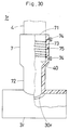
- Fig. 30 is a partially cutaway view showing a practical example of the pipe connecting member shown in Fig. 27
- Fig. 31 is a partially cutaway view showing a different embodiment of the pipe connecting member shown in Fig. 27
- Fig. 32 is a partial sectional view showing the state of installing a stopping ring in the fusion part of the receiving member of the pipe connecting member
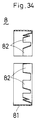
- Fig. 33 is a front view showing the stopping ring
- Fig. 33 is a front view showing the stopping ring
- Fig. 33 is a front view showing the stopping ring, Fig.
- Fig. 34 is a sectional view of line I-I in Fig. 33
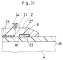
- Fig. 35 and Fig. 36 are sectional views of essential parts for explaining the action of the stopping ring
- Fig. 37 and Fig. 38 are sectional views of essential parts for explaining the action of the stopping ring in different shapes
- Fig. 39 is a partially cutaway view showing a further different embodiment of a resin pipe with a receiving port as a practical example of the pipe connecting member.
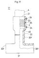
- Fig. 1 is a partial cutaway view showing an embodiment of a pipe connecting member 1 according to the invention.
- a receiving member 2 is connected butt to butt to an opening end 30 of a conduit composing part 3.
- the receiving member 2 is formed cylindrically, and a fusion part 21 is formed at its one end, while a connecting part 22 is formed at the other end.
- a resin pipe 4 can be fitted in its inner circumference. Besides, in the inner circumference, a coil 23 heated by energization is buried, and as the coil 23 generates heat, the resin surrounding the coil 23 is fused.
- the inner wall of the fusion part 21 and the outer wall of the resin pipe 4 are fused and melted together.
- the coil 23 is buried all around the fusion part 21 so as to keep a sufficient melting area by fusion.
- An end of the coil 23 is wired to an energization terminal 24 projecting from the outer circumference of the fusion part 21, so as to be energized from the energization terminal 24.
- an indicator 25 is provided, so that the fusion state around the coil 23 may be understood by this indicator 25.
- the base end portion of the fusion part 21 is reduced in diameter to prevent penetration of the end 40 of the resin pipe 4 inserted in the fusion part 21.
- the connecting part 22 is extended from the base end portion of the fusion part 21, and is formed in the same diameter and thickness as the opening end portion 30 of the conduit composing part 3. It can be connected to the opening end portion 30 of the conduit composing part 3 by butt welding.
- receiving member 2 is wound around the in-core (not shown) of the coil 23 covered with a resin layer 230, usually. It is disposed in a mold (not shown), and the resin material is injection molded at high pressure. However, if the diameter of the receiving member 2 is large, a more resin material must be injected. Accordingly, as shown in Fig. 2, a sheath tube 20 composing the outer layer of the receiving member 2 is disposed outside of the coil 23 covered with the resin layer 230, and the resin material may be injection molded by integrating the sheath tube 20 and coil 23.
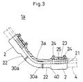
- the pipe connecting member 1 may be connected to the resin pipe 4 installed in any conduit by butt connection of a proper receiving member 2 possessing a connecting part 22 to be butt-connected to the opening end portion 30, to the opening end portion 30 of the desired conduit composing part 3. That is, as shown in Fig. 3, by butt connection of the connecting part 22 of the receiving member 2 to the opening end portion 30a of a reducing pipe 3a having a large curvature, a bend joint 1a may be formed, and as shown in Fig. 4, by butt connection of the connecting part 22 of the receiving member 2 to the opening end portion 30b of a reducing pipe 3b having a small curvature, an elbow joint 1b may be formed. Besides, as shown in Fig.
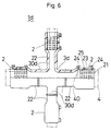
- a cross joint 1c may be formed, and as shown in Fig. 6, by butt connection of the connecting part 22 of the receiving member 2 to the opening end portion 30d of a cross pipe 3d in different diameter at the pipe end, a reducing cross joint 1d may be formed.
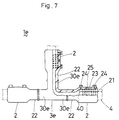
- a tee joint 1e may be formed, and as shown in Fig. 8, by butt connection of the connecting part 22 of the receiving member 2 to the opening end portion 30f of a T-pipe 3f in a different diameter at the pipe end, a reducing tee joint 1f may be formed.
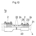
- a reducer joint 1g may be formed.
- This reducer joint 1g may be, as shown in Fig. 10, formed also by connecting the connecting parts 22 of the receiving member 2 different in the diameter of the fusion part 21.
- a receiving joint 1h of fitting adhesion type may be formed.
- a seal receiving joint 1i may be formed.
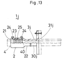
- a flange receiving joint 1j may be formed.
- a pipe end closure member 1k for closure of pipe end may be formed.
- a transition joint 11 may be formed.
- the other end portion side of the metal pipe 33 may form various joints, such as flange joint (not shown) and welded joint 33a.
- the resin pipe main body 34 may be also formed in various shapes such as branch pipe, reducing pipe, bent pipe, and elbow pipe (not shown).
- the receiving member 2 is connected butt to butt to all the opening end portions 30 of the pipe connecting members 3 mentioned above, but such structure is not particularly limited, and a proper number of receiving members 2 may be connected, as required, to the desired opening end portions 30.
- a resin pipe with a receiving port 1m may be formed.
- a tee joint 1f may be formed.
- a Y-pipe joint 1n may be formed.
- a Y-pipe joint 1n may be formed.
- an S-bend joint 1o may be formed.
- a J-bend joint 1p may be formed, and as shown in Fig.
- a J-bend pipe 1q may be formed. Furthermore, as shown in Fig. 22, by connecting the connecting part 22 of the receiving member 2 to one position only of the opening end portion 30g of the reducing pipe 3g, the reducer joint 1g may be formed.
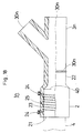
- Fig. 23 through Fig. 26 represent other embodiment of the pipe connecting member 1 of the invention. In this embodiment, however, only the receiving member 5 is different from the receiving member 2 in the foregoing embodiments, and only this receiving member 5 is explained below.
- the same constituent elements as in the foregoing embodiments are identified with the same reference numbers.
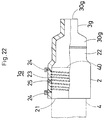
- the receiving member 5 is cylindrical, and its one end is a fusion part 51, while the other end is a connecting part 52.
- a resin pipe 4 may be fitted in its inner circumference.
- a coil 53 heated by energization is buried.
- the end of the coil 53 is wired to an energization terminal 54 projecting on the outer circumference of the fusion part 51 so as to be energized from the energization terminal 54.
- An indicator 55 is provided on the outer circumference of the fusion part 51.
- the connecting part 52 is reduced in diameter, in its inner circumference, as going inward.
- a stopped 56 is projecting to arrest penetration of the conduit composing part 3 and resin pipe 5 inserted from both the fusion part 51 and connecting part 52.
- composed receiving member 5 is usually obtained by disposing an in-core (not shown) winding a coil 53 in a mold (not shown), and injecting molding a resin material at high pressure, but when the diameter of the receiving member 5 is large, a more resin material must be injected. Accordingly, as shown in Fig. 24, outside the coil 53 covered with a resin layer 530, a sheath tube 50 for composing the outer layer of the receiving member 5 is disposed, and the resin material may be injected molded so as to integrate the sheath tube 50 and coil 53.
- the pipe connecting member 1 is formed.
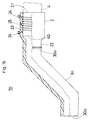
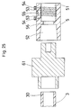
- a fusion machine 61 may be used so as to be bonded with the outer circumference of the opening end portion 30 of the conduit composing part 3 and the inner circumference of the connecting part 52 of the receiving member 5.
- the fusion machine 61 is bonded to the outer circumference of the opening end portion 30 of the conduit composing part 3 and to the inner circumference of the connecting part 52 of the receiving part 5, and after fusing these junction parts, they are detached off the fusion machine 61, and in the same fused state, the outer circumference of the opening end portion 30 of the conduit composing part 3 and the inner circumference of the connecting part 52 of the receiving member 5 are joined.
- the connecting part 52 and the opening end portion 30 are integrated by the fusion machine 61, but, as shown in Fig. 26, it may be also possible to feed current through an energization terminal 58 by burying a coil 57 heated by energization, in the connecting part 52.
- Fig. 27 through Fig. 31 refer to a further different embodiment of the pipe connecting member 1 of the invention.
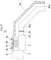
- the receiving member 7 is cylindrical, and its one end is a fusion part 71, while the other end is a connecting part 72.
- resin pipe 4 can be fitted in its inner circumference.
- a coil 73 to be heated by energization is buried.
- the end of the coil 73 is wired to an energization terminal 74 projecting on the outer circumference of the fusion part 71 so as to be energized from the energization terminal 74.
- an indicator 75 is provided on the outer circumference of the fusion part 71.
- the base end portion of the fusion part 71 is reduced in diameter to arrest penetration of the end portion 40 of the resin pipe 4 inserted in the fusion part 71.
- the connecting part 72 is reduced in diameter in its inner circumference so as to be inserted in the opening end portion 30 of the conduit composing part 3.
- Such receiving member 7 is obtained by disposing an in-core (not shown) winding the coil 73 in a mold (not shown), and injection molding a resin material at high pressure, but when the receiving member 7 is large in diameter, a more resin material must be injected. Therefore, as shown in Fig. 28, a sheath tube 70 for composing the outer layer of the receiving member 7 is disposed outside of the coil 73 coated with a resin layer 730, and the resin material may be injection molded by integrating the sheath tube 70 and coil 73.
- the pipe connecting member 1 is formed.
- a fusion machine 62 may be used for joining the inner circumference of the opening end portion 30 of the conduit composing part 3 and the outer circumference of the connecting part 72 of the receiving member 7.
- the fusion machine 62 is joined to the inner circumference of the opening end portion 30 of the conduit composing part 3 and the outer circumference of the connecting part 72 of the receiving member 7, and the junction portions are fused, and taken out of the fusion machine 62, and in this fusion state, consequently, the inner circumference of the opening end portion 30 of the conduit composing part 3 and the outer circumference of the connecting part 72 of the receiving member 7 are joined. By cooling the fitted portions, they are integrated.
- a tee joint 1r may be formed by inserting and integrating the connecting part 72 of the receiving member 7 in the opening end portion 30r.
- the connecting part 72 and the opening end portion 30 are integrated by the fusion machine 62, but as shown in Fig. 31, it may be also designed to energize from an energization terminal 77 by burying a coil 76 heated by energization in the connecting part 72.
- Fig. 32 through Fig. 38 relate to a further different embodiment of the pipe connecting member 1 of the invention.
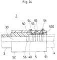
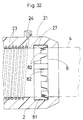
- the annular groove 27 is disposed around the inner circumference near the opening part of the fusion part 21.
- the stopping ring 8 is composed of, as shown in Fig. 33 and Fig. 34, a base material 81 curving and forming a plate-shaped wire material in a ring shape, and plural detent pieces 82 disposed on the base material 81.
- the base material 81 is not a complete endless ring, but a gap W is formed between the ends.
- the detent pieces 82 are disposed in the peripheral edge at one end of the base material 81, and are projected in an oblique direction toward the central direction of the stopping ring 8 so that an acute angle may be formed between the detent pieces 82 and the base material 81.
- the stopping ring 8 is contracted in diameter so as to fill up the gap W, and is inserted into the annular groove 27 from the vicinity of the opening of the fusion part 21.
- the stopping ring 8 is dilated again in the annular groove 27 of the portion corresponding to the gap W, and is disposed in the annular groove 27.
- the detent pieces 82 formed in the stopping ring 8 must be disposed so that the front end may be directed to the inner side of the fusion part 21.
- the resin pipe 4 can be fixed inside the fusion part 21, and it is not necessary to fix with jig (not shown) in the fusion work.
- the resin pipe 4 inserted in the fusion part 21 is centered in the central position by the detent pieces 82.
- the materials are not particularly limited as far as the stopping ring 8 can be inserted in the annular groove 27 by dilating or contracting the diameter, and the detent pieces 82 may be deformed elastically, and they may be composed of metals, plastics, and other materials.
- the stopping ring 8 is not limited to the above example alone, but, for example, the stopping ring 9 as shown in Fig. 37 and Fig. 38 may be also used.
- this stopping ring 9 a detent protrusion 91 is disposed on the inner circumference, and a slope 92 is formed on the outer circumference so as to be freely fitted in the annular ring 27.
- the annular groove 27 has a slope 28 formed at the position corresponding to the slope 92 of the stopping ring 9. That is, when the resin pipe 4 is inserted in the fusion part 21 having the stopping ring 9 (arrow A direction), the stopping ring 9 is dilated, and the resin pipe 4 is inserted.
- Fig. 39 shows other embodiment of a resin pipe with a receiving opening 1m, of the pipe connecting member 1 according to the invention.
- the same constituent elements as in the foregoing embodiments are identified with same reference numbers.
- the resin pipe with receiving opening 1m formed by using the receiving member 2 is explained, but it is the same in the resin pipe with receiving opening (not shown) formed by using the receiving member 5 or receiving member 7 shown in the other embodiments.
- This resin pipe with receiving opening 1m is composed of a female type receiving member 241 and a male type terminal pin 242 to be mutually screwed with an energization terminal 24 of the receiving member 2.
- the receiving member 241 is preliminarily buried in the receiving member 2, and at the time of fusion, consequently, the terminal pin 242 is screwed to the receiving member 241 to fuse.
- Taper surfaces 29 are formed in the peripheral areas at both ends of the receiving member 2, and it is designed so that the resin pipe with receiving port 1m may be used in the propulsion process.
- the terminal pin 242 since the terminal pin 242 is detachable, the terminal pin 242 may be detached beforehand, at the time of transportation or the like, so that the outer circumference of the receiving member 2 may be free from protrusion, and therefore breakage of the energization terminal 24 may be prevented.
- the resin pipe with receiving port 1m is used in the propulsion process, the resistance of the soil may be reduced, so that the job may be done easily.
- the pipe connecting member of the invention excels in productivity and installation characteristics in various pipings, and the fusion job may be done easily and simply.
Abstract
Description
- The present invention relates to a pipe connecting member used for connecting resin pipes end to end.
- Various types have been hitherto proposed as the pipe connecting member for burying a coil heated by energization in a joint main body.
- For example, as known in the pipe connecting member disclosed in the Japanese Patent Publication No. 4429/1958, coils are buried in the end portions of a branch pipe formed in a T-shape or pipe bodies in various shapes, and by energizing the individual coils with the end portion of resin pipe inserted in each end portion of the pipe body, the end portions of the resin pipes are connected.
- In the case of this pipe connecting member, however, since the coils are directly buried in the end portions of the pipe body formed by injection molding or the like to form in one body, every time the diameter of the resin pipe to be connected is changed, the pipe connecting member suited to the diameter is required. That is, these pipe connecting members must be manufactured all in different molds in order to prepare multiple pipe connecting members suited to a variety of resin pipes, and hence the productivity is poor and it is not rational.
- Accordingly, for example as shown in the Japanese Patent Publication No. 40743/1989, other pipe connecting member is proposed, in which the coil is buried in the entire inner circumference of the joint main body, and by energizing the coil with the end portions of the resin pipes inserted from both side of the joint main body, the resin pipes are connected freely.
- In this case, although the resin pipes of various diameters may be directly connected, the resin pipes connected in the joint main body must be held and fused at once, and the installation work is complicated and the installation time is long. Besides, since the resin pipes inserted from both ends of the joint main body are fused at once, a large electric power is required in the case of resin pipe of a large diameter. If a large electric power is not available, at a lower electric power, the energization time must be extended to fuse.
- It is therefore attempted, as disclosed in the Japanese Patent Provisional Publication No. 500452/1989, to use a resin pipe preliminarily having an electro-fusion function at one end.
- That is, in this resin pipe, one end is dilated, and a coil heated by energization is inserted in the dilated part, and the end portion of each pipe body is inserted into the dilated part to fuse.
- In the case of this resin pipe, however, since one end is dilated, the wall thickness decreases in the dilated part, and a sufficient strength is not obtained. Besides, the residual stress at the time of dilating is large, and shrinkage may take place in the course of time after dilating, and a sufficient dimensional precision may not be obtained. Yet, although the coil is disposed in the dilated part by inserting the coil at the time of dilating and then cooling, it is not formed sufficiently in one body substantially, and enough fusion is not attained when fusing.
- When connecting the resin pipe forming a joint part in various shapes such as flange surface to the pipe connecting members described above, it is necessary to connect an intermediate member to the pipe connecting member after interposing the intermediate member possessing a flange surface that can be connected with the flange surface, which results in a spliced piping. As a result, the cost for connection and installation expense are increased. Similarly, when one resin pipe is made of polyethylene and the other resin pipe is made of vinyl chloride, they cannot be directly fused, and a spliced piping is inevitable.
- Furthermore, when connecting the resin pipes by using such pipe connecting members, marking job is required before fusing, which is also annoying. Besides, the marking job serves only for discovering deviation in resin pipes, and will not prevent deviation. In the fusion work, therefore, the resin pipes must be fixed with jigs to prevent from slipping out of the pipe connecting member, and it is always required to carry jigs.
- The invention is devised in the light of such background, and is hence intended to present a pipe connecting member excellent in productivity and installation efficiency in various pipes, and capable of performing fusion job easily and simply.
- The invention presents a pipe connecting member comprising one or a plurality of receiving members, formed cylindrically, having one end provided with a fusion part to which an end portion of a resin pipe may be fitted and in which a coil heated by energization is buried, and the other end provided with a connecting part, and a conduit composing part possessing at least one opening, wherein the receiving member is connected to an arbitrary opening of the conduit composing part through its connecting part.
- In the pipe connecting member of the invention, the connecting part of the receiving member may be connected butt to butt to the opening of the conduit composing part.
- In the pipe connecting member of the invention, the opening of the conduit composing part may be inserted in the connecting part of the receiving member to be integrated, and this integration may be achieved by fusion by heating of the coil buried in the connecting part.
- In the pipe connecting member of the invention, the connecting part of the receiving member may be fitted into the opening of the conduit composing part to be integrated, and this integration may be achieved by fusion by heating of the coil buried in the connecting part.
- In the pipe connecting member of the invention, the fusion part of the receiving member may be provided with stopping means to be engaged with the resin pipe only in the withdrawing direction of the resin pipe inserted in the fusion part.
- In the pipe connecting member of the invention, the conduit composing part possesses one or two or more kinds of bent part, branch part, reducing part and joint part.
- In the pipe connecting member of the invention, the conduit composing part may be a straight pipe.
- In the pipe connecting member of the invention, the conduit composing part may be a straight pipe possessing an opening in the outer circumference, and the connecting part of the receiving member may be fitted in this opening to be integrated.
- In the pipe connecting member of the invention, the receiving member may be tapered with a taper part formed in the outer circumferential end portion.
- In the pipe connecting member of the invention, a coil in spiral state may be inserted in the sheath tube composing the outer layer in the receiving member, and the both are integrated by a resin material filling up the both.
- The pipe connecting member of the invention in the above constitution is formed by connecting the receiving member to the conduit composing part, and therefore it is not necessary to use a forming die for every pipe connecting member, and a wide variety of pipe connecting member may be formed by the combination of the receiving members and conduit composing parts. Besides, if the applicable piping location is known, the receiving member and conduit composing part may be freely connected depending on the piping location, so that a desired pipe connecting member may be formed.
- Besides, by tapering the receiving member, the resistance of the soil when applied in the propulsion process may be reduced. Moreover, by disposing the stopping means in the fusion part of the receiving member, it is not necessary to fix to jigs or the like in the fusion work, and the resin pipe inserted in the fusion part may be also aligned.
- In addition, by composing the outer layer of the receiving member with the sheath tube, the pipe connecting member of large diameter may be formed efficiently.
- Fig. 1 is a partially cutaway view showing an embodiment of a pipe connecting member of the invention, Fig. 2 is a partially cutaway view showing other embodiment of the receiving member in the pipe connecting member shown in Fig. 1, Fig. 3 through Fig. 22 are partially cutaway views showing practical examples of the pipe connecting member, Fig. 23 is a partially cutaway view showing a different embodiment of the pipe connecting member, Fig. 24 is a partially cutaway view showing other embodiment of the receiving member in the pipe connecting member shown in Fig. 23, Fig. 25 is an explanatory diagram showing a manufacturing method of the pipe connecting member shown in Fig. 23, Fig. 26 is a partially cutaway view showing another embodiment of the pipe connecting member shown in Fig. 23, Fig. 27 is a partially cutaway view showing a further different embodiment of the pipe connecting member, Fig. 28 is a partially cutaway view showing other embodiment of the receiving member in the pipe connecting member shown in Fig. 27, Fig. 29 is an explanatory diagram showing a manufacturing method of the pipe connecting member shown in Fig. 27, Fig. 30 is a partially cutaway view showing a practical example of the pipe connecting member shown in Fig. 27, Fig. 31 is a partially cutaway view showing a different embodiment of the pipe connecting member shown in Fig. 27, Fig. 32 is a partial sectional view showing the state of installing a stopping ring in the fusion part of the receiving member of the pipe connecting member, Fig. 33 is a front view showing the stopping ring, Fig. 34 is a sectional view of line I-I in Fig. 33, Fig. 35 and Fig. 36 are sectional views of essential parts for explaining the action of the stopping ring, Fig. 37 and Fig. 38 are sectional views of essential parts for explaining the action of the stopping ring in different shapes, and Fig. 39 is a partially cutaway view showing a further different embodiment of a resin pipe with a receiving port as a practical example of the pipe connecting member.
- Referring now to the drawings, some of the embodiments of the invention are described in detail below.
- Fig. 1 is a partial cutaway view showing an embodiment of a
pipe connecting member 1 according to the invention. - In this
pipe connecting member 1, a receivingmember 2 is connected butt to butt to anopening end 30 of aconduit composing part 3. - The
receiving member 2 is formed cylindrically, and afusion part 21 is formed at its one end, while a connectingpart 22 is formed at the other end. - In the
fusion part 21, aresin pipe 4 can be fitted in its inner circumference. Besides, in the inner circumference, acoil 23 heated by energization is buried, and as thecoil 23 generates heat, the resin surrounding thecoil 23 is fused. - That is, by inserting the
end 40 of theresin pipe 4 into thefusion part 21 and energizing thecoil 23, the inner wall of thefusion part 21 and the outer wall of theresin pipe 4 are fused and melted together. For this purpose, thecoil 23 is buried all around thefusion part 21 so as to keep a sufficient melting area by fusion. An end of thecoil 23 is wired to anenergization terminal 24 projecting from the outer circumference of thefusion part 21, so as to be energized from theenergization terminal 24. On the outer circumference of thefusion part 21, anindicator 25 is provided, so that the fusion state around thecoil 23 may be understood by thisindicator 25. Furthermore, the base end portion of thefusion part 21 is reduced in diameter to prevent penetration of theend 40 of theresin pipe 4 inserted in thefusion part 21. - The connecting
part 22 is extended from the base end portion of thefusion part 21, and is formed in the same diameter and thickness as theopening end portion 30 of theconduit composing part 3. It can be connected to theopening end portion 30 of theconduit composing part 3 by butt welding. - Thus composed receiving
member 2 is wound around the in-core (not shown) of thecoil 23 covered with aresin layer 230, usually. It is disposed in a mold (not shown), and the resin material is injection molded at high pressure. However, if the diameter of the receivingmember 2 is large, a more resin material must be injected. Accordingly, as shown in Fig. 2, asheath tube 20 composing the outer layer of the receivingmember 2 is disposed outside of thecoil 23 covered with theresin layer 230, and the resin material may be injection molded by integrating thesheath tube 20 andcoil 23. - The
pipe connecting member 1 may be connected to theresin pipe 4 installed in any conduit by butt connection of a proper receivingmember 2 possessing a connectingpart 22 to be butt-connected to theopening end portion 30, to theopening end portion 30 of the desiredconduit composing part 3. That is, as shown in Fig. 3, by butt connection of the connectingpart 22 of the receivingmember 2 to theopening end portion 30a of a reducingpipe 3a having a large curvature, a bend joint 1a may be formed, and as shown in Fig. 4, by butt connection of the connectingpart 22 of the receivingmember 2 to theopening end portion 30b of a reducingpipe 3b having a small curvature, anelbow joint 1b may be formed. Besides, as shown in Fig. 5, by butt connection of the connectingpart 22 of the receivingmember 2 to theopening end portion 30c of across pipe 3c in the same diameter at the pipe end, a cross joint 1c may be formed, and as shown in Fig. 6, by butt connection of the connectingpart 22 of the receivingmember 2 to theopening end portion 30d of across pipe 3d in different diameter at the pipe end, a reducingcross joint 1d may be formed. Furthermore, as shown in Fig. 7, by butt connection of the connectingpart 22 of the receivingmember 2 to theopening end portion 30e of a T-pipe 3e in the same diameter at the pipe end, atee joint 1e may be formed, and as shown in Fig. 8, by butt connection of the connectingpart 22 of the receivingmember 2 to theopening end portion 30f of a T-pipe 3f in a different diameter at the pipe end, a reducingtee joint 1f may be formed. - Moreover, as shown in Fig. 9, by butt connection of the connecting
part 22 of the receivingmember 2 to theopening end portion 30g of a reducingpipe 3g in a different diameter at the pipe end, areducer joint 1g may be formed. Thisreducer joint 1g may be, as shown in Fig. 10, formed also by connecting the connectingparts 22 of the receivingmember 2 different in the diameter of thefusion part 21. - Still more, as shown in Fig. 11, by butt connection of the connecting
part 22 of the receivingmember 2 to the openingend portion 30h of ajoint member 3h having a receivingport 31h of fitting adhesion type, a receiving joint 1h of fitting adhesion type may be formed. Further, as shown in Fig. 12, by butt connection of the connectingpart 22 of the receivingmember 2 to the openingend portion 30i of a joint member 3i having a receivingport 31i so as to be sealed by a seal ring, a seal receiving joint 1i may be formed. As shown in Fig. 13, by butt connection of the connectingpart 22 of the receivingmember 2 to the openingend portion 30j of ajoint member 3j possessing aflange surface 31j, a flange receiving joint 1j may be formed. As shown in Fig. 14, by butt connection of the connectingpart 22 of the receivingmember 2 to the openingend portion 30k of a blind cover member having a blind cover at one end, a pipeend closure member 1k for closure of pipe end may be formed. As shown in Fig. 15, moreover, by butt connection of the connectingpart 22 of the receivingmember 2 to the otherend opening portion 301 of a resin pipemain body 34 having ametal pipe 33 connected at one end, a transition joint 11 may be formed. In the case of this transition joint 11, the other end portion side of themetal pipe 33 may form various joints, such as flange joint (not shown) and welded joint 33a. Besides, the resin pipemain body 34 may be also formed in various shapes such as branch pipe, reducing pipe, bent pipe, and elbow pipe (not shown). - In this embodiment, the receiving
member 2 is connected butt to butt to all theopening end portions 30 of thepipe connecting members 3 mentioned above, but such structure is not particularly limited, and a proper number of receivingmembers 2 may be connected, as required, to the desired openingend portions 30. For example, as shown in Fig. 16, by connecting the connectingpart 22 of the receivingmember 2 to only one position of the openingend portion 30m of astraight pipe 3m, a resin pipe with a receivingport 1m may be formed. Besides, as shown in Fig. 17, by connecting the connectingpart 22 of the receivingmember 2 only to one position of the openingend portion 30f of the T-pipe 3f, a tee joint 1f may be formed. As shown in Fig. 18, moreover, by butt connection of the connectingpart 22 of the receivingmember 2 to one position of the openingend portion 30n of a Y-pipe 3n, a Y-pipe joint 1n may be formed. As shown in Fig. 19, by butt connection of the connectingpart 22 of the receivingmember 2 to one position of the opening end portion 30o of an S-bend pipe 3o of a large curvature, an S-bend joint 1o may be formed. As shown in Fig. 10, by butt connection of the connectingpart 22 of the receivingmember 2 at one position of the openingend portion 30p of a J-bend pipe 3p in the same axial direction in the pipe end direction, a J-bend joint 1p may be formed, and as shown in Fig. 21, by butt connection of the connectingpart 22 of the receivingmember 2 to one position of the openingend portion 30q of a J-bend pipe 3q differing by 90. in the pipe end direction, a J-bend pipe 1q may be formed. Furthermore, as shown in Fig. 22, by connecting the connectingpart 22 of the receivingmember 2 to one position only of the openingend portion 30g of the reducingpipe 3g, the reducer joint 1g may be formed. - Fig. 23 through Fig. 26 represent other embodiment of the
pipe connecting member 1 of the invention. In this embodiment, however, only the receivingmember 5 is different from the receivingmember 2 in the foregoing embodiments, and only this receivingmember 5 is explained below. In the drawings, the same constituent elements as in the foregoing embodiments are identified with the same reference numbers. - The receiving
member 5 is cylindrical, and its one end is afusion part 51, while the other end is a connectingpart 52. - In the
fusion part 51, aresin pipe 4 may be fitted in its inner circumference. In the inner circumference, moreover, acoil 53 heated by energization is buried. The end of thecoil 53 is wired to anenergization terminal 54 projecting on the outer circumference of thefusion part 51 so as to be energized from theenergization terminal 54. Anindicator 55 is provided on the outer circumference of thefusion part 51. - The connecting
part 52 is reduced in diameter, in its inner circumference, as going inward. In the inner circumference of the boundary portion of the base end portion of the connectingpart 52 and the base end portion of thefusion part 51, a stopped 56 is projecting to arrest penetration of theconduit composing part 3 andresin pipe 5 inserted from both thefusion part 51 and connectingpart 52. - Thus composed receiving
member 5 is usually obtained by disposing an in-core (not shown) winding acoil 53 in a mold (not shown), and injecting molding a resin material at high pressure, but when the diameter of the receivingmember 5 is large, a more resin material must be injected. Accordingly, as shown in Fig. 24, outside thecoil 53 covered with aresin layer 530, asheath tube 50 for composing the outer layer of the receivingmember 5 is disposed, and the resin material may be injected molded so as to integrate thesheath tube 50 andcoil 53. - By fitting and integrating the opening
end portion 30 of theconduit composing part 3 to the connectingpart 52 of thus formed receivingmember 5, thepipe connecting member 1 is formed. As the method of integrating, as shown in Fig. 25, afusion machine 61 may be used so as to be bonded with the outer circumference of the openingend portion 30 of theconduit composing part 3 and the inner circumference of the connectingpart 52 of the receivingmember 5. That is, thefusion machine 61 is bonded to the outer circumference of the openingend portion 30 of theconduit composing part 3 and to the inner circumference of the connectingpart 52 of the receivingpart 5, and after fusing these junction parts, they are detached off thefusion machine 61, and in the same fused state, the outer circumference of the openingend portion 30 of theconduit composing part 3 and the inner circumference of the connectingpart 52 of the receivingmember 5 are joined. - By cooling the junction parts, they are integrated. In this embodiment, the connecting
part 52 and the openingend portion 30 are integrated by thefusion machine 61, but, as shown in Fig. 26, it may be also possible to feed current through anenergization terminal 58 by burying acoil 57 heated by energization, in the connectingpart 52. - Fig. 27 through Fig. 31 refer to a further different embodiment of the
pipe connecting member 1 of the invention. - In this embodiment, only the receiving
member 7 is different from the receivingmember 2 of the former embodiment, and only the receivingmember 7 is explained below. In these drawings, the same constituent elements as in the above embodiment are identified with the same reference numbers. - The receiving
member 7 is cylindrical, and its one end is afusion part 71, while the other end is a connectingpart 72. - In the
fusion part 71,resin pipe 4 can be fitted in its inner circumference. In the inner circumference, moreover, acoil 73 to be heated by energization is buried. The end of thecoil 73 is wired to anenergization terminal 74 projecting on the outer circumference of thefusion part 71 so as to be energized from theenergization terminal 74. On the outer circumference of thefusion part 71, anindicator 75 is provided. The base end portion of thefusion part 71 is reduced in diameter to arrest penetration of theend portion 40 of theresin pipe 4 inserted in thefusion part 71. - The connecting
part 72 is reduced in diameter in its inner circumference so as to be inserted in the openingend portion 30 of theconduit composing part 3. - Such receiving
member 7 is obtained by disposing an in-core (not shown) winding thecoil 73 in a mold (not shown), and injection molding a resin material at high pressure, but when the receivingmember 7 is large in diameter, a more resin material must be injected. Therefore, as shown in Fig. 28, asheath tube 70 for composing the outer layer of the receivingmember 7 is disposed outside of thecoil 73 coated with aresin layer 730, and the resin material may be injection molded by integrating thesheath tube 70 andcoil 73. - By fitting and integrating the connecting
part 72 to the openingend portion 30 of theconduit composing part 3, thepipe connecting member 1 is formed. As this integrating method, as shown in Fig. 29, afusion machine 62 may be used for joining the inner circumference of the openingend portion 30 of theconduit composing part 3 and the outer circumference of the connectingpart 72 of the receivingmember 7. That is, thefusion machine 62 is joined to the inner circumference of the openingend portion 30 of theconduit composing part 3 and the outer circumference of the connectingpart 72 of the receivingmember 7, and the junction portions are fused, and taken out of thefusion machine 62, and in this fusion state, consequently, the inner circumference of the openingend portion 30 of theconduit composing part 3 and the outer circumference of the connectingpart 72 of the receivingmember 7 are joined. By cooling the fitted portions, they are integrated. In the case of the receivingmember 7 of the embodiment, meanwhile, since it is intended to integrate by inserting the connectingpart 72 into the openingend portion 30, a tee joint 1r may be formed by inserting and integrating the connectingpart 72 of the receivingmember 7 in the openingend portion 30r. In this embodiment, moreover, the connectingpart 72 and the openingend portion 30 are integrated by thefusion machine 62, but as shown in Fig. 31, it may be also designed to energize from anenergization terminal 77 by burying acoil 76 heated by energization in the connectingpart 72. - Fig. 32 through Fig. 38 relate to a further different embodiment of the
pipe connecting member 1 of the invention. - In this embodiment, by disposing an
annular groove 27 around the inner circumference of thefusion part 21 of the receivingmember 2 in the foregoing embodiment, and disposing a stoppingring 8 in theannular groove 27, it is intended to prevent slip-out of theresin pipe 4 inserted in thefusion part 21 by the stoppingring 8. Only the different points are explained herein, and the other explanations are omitted. In these drawings, the same constituent elements as in the foregoing embodiment are identified with same reference numbers. The following description relates to thepipe connecting member 1 provided with the receivingmember 2, but the stoppingring 8 may be similarly disposed in thepipe connecting member 1 furnished with the receivingmember 5 or receivingmember 7 shown in the other preceding embodiments. - The
annular groove 27 is disposed around the inner circumference near the opening part of thefusion part 21. - The stopping
ring 8 is composed of, as shown in Fig. 33 and Fig. 34, abase material 81 curving and forming a plate-shaped wire material in a ring shape, andplural detent pieces 82 disposed on thebase material 81. However, thebase material 81 is not a complete endless ring, but a gap W is formed between the ends. Thedetent pieces 82 are disposed in the peripheral edge at one end of thebase material 81, and are projected in an oblique direction toward the central direction of the stoppingring 8 so that an acute angle may be formed between thedetent pieces 82 and thebase material 81. - The stopping
ring 8 is contracted in diameter so as to fill up the gap W, and is inserted into theannular groove 27 from the vicinity of the opening of thefusion part 21. - Consequently, the stopping
ring 8 is dilated again in theannular groove 27 of the portion corresponding to the gap W, and is disposed in theannular groove 27. In this state, however, thedetent pieces 82 formed in the stoppingring 8 must be disposed so that the front end may be directed to the inner side of thefusion part 21. - As shown in Fig. 35, when the
resin pipe 4 is inserted in thefusion part 21 disposing the stopping ring 8 (arrow A direction), the slope of thedetent pieces 82 is pressed by the outer circumference of theresin pipe 4, and thedetent pieces 82 are deformed elastically so that theresin pipe 4 may be inserted. Then, as shown in Fig. 36, when it is attempted to draw out theresin pipe 4 from the fusion part 21 (arrow B direction), the front end of thedetent pieces 82 bites into the outer circumference of theresin pipe 4 and is fixed so as not to slip out. As a result, only by pushing theresin pipe 4 into thefusion part 21, theresin pipe 4 can be fixed inside thefusion part 21, and it is not necessary to fix with jig (not shown) in the fusion work. At the same time, theresin pipe 4 inserted in thefusion part 21 is centered in the central position by thedetent pieces 82. - Incidentally, the materials are not particularly limited as far as the stopping
ring 8 can be inserted in theannular groove 27 by dilating or contracting the diameter, and thedetent pieces 82 may be deformed elastically, and they may be composed of metals, plastics, and other materials. - The stopping
ring 8 is not limited to the above example alone, but, for example, the stoppingring 9 as shown in Fig. 37 and Fig. 38 may be also used. In this stoppingring 9, adetent protrusion 91 is disposed on the inner circumference, and aslope 92 is formed on the outer circumference so as to be freely fitted in theannular ring 27. Besides, theannular groove 27 has aslope 28 formed at the position corresponding to theslope 92 of the stoppingring 9. That is, when theresin pipe 4 is inserted in thefusion part 21 having the stopping ring 9 (arrow A direction), the stoppingring 9 is dilated, and theresin pipe 4 is inserted. When it is attempted to pull theresin pipe 4 out of the fusion part 21 (arrow B direction), theslope 92 of the stoppingring 9 rides over theslope 28 of theannular groove 27. As a result, thedetent protrusion 91 bites into the outer circumference of theresin pipe 4, and is fixed without slipping out. - Fig. 39 shows other embodiment of a resin pipe with a receiving
opening 1m, of thepipe connecting member 1 according to the invention. In the drawing, the same constituent elements as in the foregoing embodiments are identified with same reference numbers. Herein, the resin pipe with receivingopening 1m formed by using the receivingmember 2 is explained, but it is the same in the resin pipe with receiving opening (not shown) formed by using the receivingmember 5 or receivingmember 7 shown in the other embodiments. - This resin pipe with receiving
opening 1m is composed of a femaletype receiving member 241 and a male type terminal pin 242 to be mutually screwed with anenergization terminal 24 of the receivingmember 2. The receivingmember 241 is preliminarily buried in the receivingmember 2, and at the time of fusion, consequently, the terminal pin 242 is screwed to the receivingmember 241 to fuse. Taper surfaces 29 are formed in the peripheral areas at both ends of the receivingmember 2, and it is designed so that the resin pipe with receivingport 1m may be used in the propulsion process. - Using this resin pipe with receiving
port 1m, since the terminal pin 242 is detachable, the terminal pin 242 may be detached beforehand, at the time of transportation or the like, so that the outer circumference of the receivingmember 2 may be free from protrusion, and therefore breakage of theenergization terminal 24 may be prevented. When the resin pipe with receivingport 1m is used in the propulsion process, the resistance of the soil may be reduced, so that the job may be done easily. - Thus, the pipe connecting member of the invention excels in productivity and installation characteristics in various pipings, and the fusion job may be done easily and simply.
Claims (23)
- A pipe connecting member comprising one or a plurality of receiving members, formed cylindrically, having one end provided with a fusion part to which an end portion of a resin pipe may be fitted and in which a coil heated by energization is buried, and the other end provided with a connecting part, and a conduit composing part possessing at least one opening,
wherein the receiving member is connected to an arbitrary opening of the conduit composing part through its connecting part. - A pipe connecting member of claim 1, wherein the connecting part of the receiving member is connected butt to butt to the opening of the conduit composing part.
- A pipe connecting member of claim 1, wherein the opening of the conduit composing part is inserted in the connecting part of the receiving member to be integrated,
- A pipe connecting member of claim 3, wherein a coil heated by energization is buried in the connecting part of the receiving member, and the integration is effected by fusion by the heat generation of the coil.
- A pipe connecting member of claim 1, wherein the connecting part of the receiving member is fitted into the opening of the conduit composing part to be integrated,
- A pipe connecting member of claim 5, wherein a coil heated by energization is buried in the connecting part of the receiving member, and the integration is effected by fusion by the heat generation of the coil.
- A pipe connecting member of claim 1, wherein the fusion part of the receiving member is provided with stopping means to be engaged with the resin pipe only in the withdrawing direction of the resin pipe inserted in the fusion part.
- A pipe connecting member of claim 7, wherein the connecting part of the receiving member is connected butt to butt to the opening of the conduit composing part.
- A pipe connecting member of claim 7, wherein the opening of the conduit composing part is inserted in the connecting part of the receiving member to be integrated,
- A pipe connecting member of claim 9, wherein a coil heated by energization is buried in the connecting part of the receiving member, and the integration is effected by fusion by the heat generation of the coil.
- A pipe connecting member of claim 7, wherein the connecting part of the receiving member is fitted into the opening of the conduit composing part to be integrated.
- A pipe connecting member of claim 11, wherein a coil heated by energization is buried in the connecting part of the receiving member, and the integration is effected by fusion by the heat generation of the coil.
- A pipe connecting member of claim 8, wherein the conduit composing part possesses one or two or more kinds of bent part, branch part, reducing part and joint part.
- A pipe connecting member of claim 8, wherein the conduit composing part is a straight pipe.
- A pipe connecting member of claim 9, wherein the conduit composing part possesses one or two or more kinds of bent part, branch part, reducing part and joint part.
- A pipe connecting member of claim 9, wherein the conduit composing part is a straight pipe.
- A pipe connecting member of claim 11, wherein the conduit composing part is a straight pipe possessing an opening in the outer circumference, and the connecting part of the receiving member is fitted in this opening to be integrated.
- A pipe connecting member of claim 14, wherein the receiving member is tapered with a taper part formed in the outer circumferential end portion.
- A pipe connecting member of claim 16, wherein the receiving member is tapered with a taper part formed in the outer circumferential end portion.
- A pipe connecting member of claim 1, wherein a coil in spiral state is inserted in the sheath tube composing the outer layer in the receiving member, and the both are integrated by a resin material filling up the both.
- A pipe connecting member of claim 20, wherein the connecting part of the receiving member is connected butt to butt to the conduit composing part.
- A pipe connecting member of claim 20, wherein the opening of the conduit composing part is fitted to the connecting part of the receiving member.
- A pipe connecting member of claim 20, wherein the connecting part of the receiving member is inserted into the opening of the conduit composing part.
Applications Claiming Priority (7)
| Application Number | Priority Date | Filing Date | Title |
|---|---|---|---|
| JP88245/91 | 1991-04-19 | ||
| JP8824591 | 1991-04-19 | ||
| JP10443291 | 1991-05-09 | ||
| JP104432/91 | 1991-05-09 | ||
| JP151423/91 | 1991-06-24 | ||
| JP15142391 | 1991-06-24 | ||
| PCT/JP1992/000500 WO1992018322A1 (en) | 1991-04-19 | 1992-04-17 | Pipe joint member |
Publications (3)
| Publication Number | Publication Date |
|---|---|
| EP0535247A1 true EP0535247A1 (en) | 1993-04-07 |
| EP0535247A4 EP0535247A4 (en) | 1993-09-08 |
| EP0535247B1 EP0535247B1 (en) | 1997-07-09 |
Family
ID=27305770
Family Applications (1)
| Application Number | Title | Priority Date | Filing Date |
|---|---|---|---|
| EP92908284A Expired - Lifetime EP0535247B1 (en) | 1991-04-19 | 1992-04-17 | Pipe joint member |
Country Status (12)
| Country | Link |
|---|---|
| US (1) | US5398974A (en) |
| EP (1) | EP0535247B1 (en) |
| JP (2) | JPH05118487A (en) |
| KR (1) | KR960010236B1 (en) |
| AT (1) | ATE155070T1 (en) |
| AU (2) | AU660669B2 (en) |
| CA (1) | CA2085886A1 (en) |
| DE (1) | DE69220745T2 (en) |
| DK (1) | DK0535247T3 (en) |
| ES (1) | ES2103941T3 (en) |
| GR (1) | GR3024847T3 (en) |
| WO (1) | WO1992018322A1 (en) |
Cited By (17)
| Publication number | Priority date | Publication date | Assignee | Title |
|---|---|---|---|---|
| WO1995003162A1 (en) * | 1993-07-20 | 1995-02-02 | British Gas Plc | A method of joining reinforced thermoplastic pipes |
| GB2282102A (en) * | 1993-09-06 | 1995-03-29 | Uponor Aldyl Ltd | Composite electrofusion pipe fitting |
| GB2272663B (en) * | 1992-01-06 | 1996-09-25 | Kubota Kk | A method of manufacturing a plastic pipe |
| GB2299291A (en) * | 1992-01-06 | 1996-10-02 | Kubota Kk | Manufacturing plastics pipe with a socket by injection moulding |
| EP0693652A3 (en) * | 1994-07-21 | 1996-10-23 | Hitachi Metals Ltd | Electric welding pipe joint |
| EP0679500A3 (en) * | 1994-04-28 | 1996-10-23 | Glynwed Plastics | Method of manufacturing an electrofusion coupler. |
| GB2311112A (en) * | 1996-03-15 | 1997-09-17 | Fusion Group Plc | Duckfoot bend fitting for connecting a mains pipe to e.g. a fire hydrant |
| GB2319576A (en) * | 1996-11-20 | 1998-05-27 | Uponor Bv | Connector for a multi-layer pipe |
| US5916468A (en) * | 1996-07-08 | 1999-06-29 | Hitachi Metals Ltd. | Electrically weldable pipe joint and production method thereof |
| GB2388635A (en) * | 2002-05-14 | 2003-11-19 | Uponor Innovation Ab | A composite electrofusion fitting |
| EP1369636A1 (en) * | 2002-06-06 | 2003-12-10 | Georg Fischer Wavin AG | Electrofusion fitting |
| GB2415024A (en) * | 2002-05-14 | 2005-12-14 | Uponor Innovation Ab | Composite electrofusion fitting |
| EP1726863A1 (en) * | 2005-05-25 | 2006-11-29 | DA-Kunststoff GmbH | Device for establishing a connection between a metal fitting and a plastic pipe |
| WO2015008028A1 (en) * | 2013-07-18 | 2015-01-22 | Pioneer Lining Technology Limited | Improved electrofusion fittng methods |
| CN105782625A (en) * | 2016-05-10 | 2016-07-20 | 河北有容管业有限公司 | Sleeve electrofusion joint device and method of winding structure wall pipe |
| EP3623681A1 (en) * | 2013-08-08 | 2020-03-18 | Proper Pipe Ehf. | Pipe fittings allowing non-destructive pressure testing of integrity of seals |
| CN111634004A (en) * | 2020-06-28 | 2020-09-08 | 江苏华源节水股份有限公司 | Use method of sliding frame type PE pipe sleeving and mounting unit |
Families Citing this family (22)
| Publication number | Priority date | Publication date | Assignee | Title |
|---|---|---|---|---|
| US5722702A (en) * | 1996-04-12 | 1998-03-03 | Arnco Corporation | Plastic pipe compression coupler |
| US5690148A (en) * | 1996-06-21 | 1997-11-25 | Ziu; Christopher G. | Closure fitting and flexibility support assembly for double-containment piping systems |
| JP2000513074A (en) * | 1996-06-25 | 2000-10-03 | ウポノール ベスローテン フェンノートシャップ | Electric welding pipe fittings |
| IT1291331B1 (en) * | 1997-05-09 | 1999-01-07 | Nupi S P A | CONNECTION WITH THERMOELECTRIC ADHESION |
| WO2001020219A1 (en) * | 1999-09-14 | 2001-03-22 | Petrotechnik Limited | Improved welding socket |
| US6406587B1 (en) * | 1999-09-30 | 2002-06-18 | Connectra Fusion Technologies, Llc | Method and an apparatus for fusing a sidewall fitting onto a plastic pipe |
| US6398264B1 (en) * | 2000-03-16 | 2002-06-04 | The United States Of America As Represented By The Administrator Of The National Aeronautics And Space Administration | Thermally activated joining apparatus |
| JP2002120291A (en) * | 2000-10-18 | 2002-04-23 | Toyotoshi Tadokoro | Method for producing resin-lined metal pipe with flange and structure of resin-lined metal pipe with flange |
| JP2002292739A (en) * | 2001-03-28 | 2002-10-09 | Acty:Kk | Method and apparatus for joining thermoplastic resin pipe |
| ATE403822T1 (en) * | 2001-10-03 | 2008-08-15 | Petrotechnik Ltd | COUPLING |
| JP2003130278A (en) * | 2001-10-30 | 2003-05-08 | Kubota Corp | Electric fusion universal joint |
| DE20213974U1 (en) | 2002-09-06 | 2002-11-07 | Henze Gmbh Kunststoffwerk | Plastic pipe |
| US20060202471A1 (en) * | 2005-03-07 | 2006-09-14 | Weisbond Bradley K | Electro-fusion joining system for thermoplastic piping systems |
| JP2006266397A (en) * | 2005-03-24 | 2006-10-05 | Yasuo Shiraishi | Pipe component |
| US9611958B1 (en) * | 2007-01-05 | 2017-04-04 | Zurn Industries, Llc | Combination mechanical/fusion pipe fitting with push connect coupling arrangement |
| US20100295299A1 (en) * | 2007-06-12 | 2010-11-25 | Orion Enterprises, Inc. | Joint and joining method for plastic pipe |
| DE102010027868B4 (en) | 2010-04-16 | 2015-01-22 | Henze Gmbh Kunststoffwerk | Plastic pipe |
| FR2963654B1 (en) * | 2010-08-06 | 2013-12-13 | Saipem Sa | DRIVING COMPRISING AN INTERNAL SHAPING AND A TUBULAR JUNCTION SLEEVE OF PLASTIC MATERIAL |
| AU2012339553B2 (en) | 2011-11-16 | 2016-05-12 | Flexpipe Systems Inc. | Flexible reinforced pipe and reinforcement tape |
| AR088888A1 (en) * | 2011-11-16 | 2014-07-16 | Flexpipe Systems Inc | CONNECTION FOR THERMOPLASTIC PIPES, ASSEMBLY AND METHOD |
| ES2581377B1 (en) * | 2016-05-13 | 2017-05-30 | Abn Pipe Systems, S.L.U. | Connection device for pipe elements |
| JP2021055745A (en) * | 2019-09-30 | 2021-04-08 | 積水化学工業株式会社 | Joint |
Citations (15)
| Publication number | Priority date | Publication date | Assignee | Title |
|---|---|---|---|---|
| GB806173A (en) * | 1956-04-20 | 1958-12-23 | Ici Ltd | Improvements in or relating to tubular connections |
| DE2352571B1 (en) * | 1973-10-17 | 1974-10-24 | Main Gaswerke Ag | Connection of a gas pipeline made of polyethylene with a metal gas pipeline |
| NL7509760A (en) * | 1974-08-16 | 1976-02-18 | Main Gaswerke Ag | CONNECTION OF A POLYETHENE GAS PIPE TO A METAL GAS PIPE. |
| DE2454706A1 (en) * | 1974-11-19 | 1976-05-26 | Messer Griesheim Gmbh | Heat weldable thermoplastics tube sleeve or tube tube connection - where the outer dia. of the tube end decreases and the inner dia. of the sleeve increases to ensure tight fit |
| EP0075901A1 (en) * | 1981-09-29 | 1983-04-06 | Von Roll Ag | Process for providing a mantle tube connection across a joint between heat insulated pipes and pipe section for carrying out said process |
| FR2516439A1 (en) * | 1981-11-13 | 1983-05-20 | Armosig | Electrically fusible liners for thermoplastic pipework joints - pre-assembled by partial fusion for satisfactory alignment |
| EP0123195A1 (en) * | 1983-04-26 | 1984-10-31 | Friedrichsfeld GmbH Keramik- und Kunststoffwerke | Screwed-gland joint |
| EP0146157A2 (en) * | 1983-11-03 | 1985-06-26 | Wavin B.V. | Device for connecting two tubular plastic cable envelopes together |
| DE3411179C1 (en) * | 1984-03-27 | 1986-01-16 | Friedrichsfeld Gmbh, Steinzeug- Und Kunststoffwerke, 6800 Mannheim | Electrical welding fitting or welding collar |
| US4852914A (en) * | 1987-06-19 | 1989-08-01 | Milfuse Systems, Inc. | Plastic pipeline having rapidly fusible joints and method of making same |
| US4865674A (en) * | 1988-10-06 | 1989-09-12 | Elkhart Products Corporation | Method of connecting two thermoplastic pipes using a barbed metal welding sleeve |
| EP0253966B1 (en) * | 1986-06-25 | 1989-12-13 | Georg Fischer Aktiengesellschaft | Moulding of a thermoplastic material |
| EP0378406A2 (en) * | 1989-01-11 | 1990-07-18 | Osaka Gas Co., Ltd. | Electrofusion joint and hot water supply header using the same |
| EP0396273A2 (en) * | 1989-05-03 | 1990-11-07 | Fusion Group Plc | Electro-fusion fittings |
| DE9113877U1 (en) * | 1990-12-20 | 1992-02-06 | Geberit Ag, Jona, St.Gallen, Ch |
Family Cites Families (23)
| Publication number | Priority date | Publication date | Assignee | Title |
|---|---|---|---|---|
| GB190817494A (en) * | 1909-03-20 | 1909-10-21 | Joseph Zeitlin | An Improved Vacuum Pump. |
| US2567639A (en) * | 1948-04-09 | 1951-09-11 | Harry L Fulton | Pipe joint and fitting |
| US2930634A (en) * | 1957-02-21 | 1960-03-29 | Coast Mfg And Supply Co | Coupler and method of joining conduits |
| NL135089C (en) * | 1963-09-28 | 1900-01-01 | ||
| US3924882A (en) * | 1974-10-04 | 1975-12-09 | Mueller Co | Stab-type coupling joint |
| CH576326A5 (en) * | 1974-12-06 | 1976-06-15 | Fischer Ag Georg | |
| JPS527016A (en) * | 1975-07-08 | 1977-01-19 | Mitsui Petrochem Ind Ltd | Connecting method of polyolefin system resin pipe |
| US4094536A (en) * | 1976-12-20 | 1978-06-13 | Continental Industries, Inc. | Meter riser |
| JPS5729114U (en) * | 1980-07-25 | 1982-02-16 | ||
| JPS58183904A (en) * | 1982-04-22 | 1983-10-27 | Asahi Chem Ind Co Ltd | Novel separative concentration method of organic solvent |
| US4508368A (en) * | 1982-03-01 | 1985-04-02 | R & G Sloane Mfg. Co., Inc. | Plastic pipe joint |
| ZW8585A1 (en) * | 1984-05-18 | 1985-09-04 | Mega Plastics Ind | Thermoplastic pipe joints |
| IT8648290A0 (en) * | 1986-07-22 | 1986-07-22 | Bonazelli Paolo | POLYETHYLENE PIPE WITH BUILT-IN ELECTRIC RESISTANCE THERMO-SEALING SYSTEM |
| JPH01206026A (en) * | 1987-10-14 | 1989-08-18 | Mitsui Petrochem Ind Ltd | Manufacture of electrofusion coupling |
| JPH01168427A (en) * | 1987-12-24 | 1989-07-03 | Hitachi Metals Ltd | Thermocouple for plastic tube joint of electric welding type |
| JPH01202423A (en) * | 1988-02-08 | 1989-08-15 | Hitachi Metals Ltd | Joining method for electric fusing type plastic pipe |
| JPH0751316B2 (en) * | 1988-04-19 | 1995-06-05 | 積水化学工業株式会社 | Method for manufacturing piping member having connection portion |
| US4906313A (en) * | 1988-05-09 | 1990-03-06 | R. W. Lyall & Company, Inc. | Fusion weld method and assembly for forming a fusion welded joint between pipe sections |
| JP2569354B2 (en) * | 1988-07-30 | 1997-01-08 | 積水化学工業株式会社 | Fittings and retaining rings for fittings |
| US4997214A (en) * | 1988-12-08 | 1991-03-05 | Dresser Industries, Inc. | Transition fitting |
| US4958857A (en) * | 1989-01-30 | 1990-09-25 | R&G Sloane Manufacturing Co. | Welding seal assembly |
| JP2932093B2 (en) * | 1990-10-08 | 1999-08-09 | 日本鋼管継手株式会社 | Conversion joint between resin tube and metal tube |
| GB9101914D0 (en) * | 1991-01-29 | 1991-03-13 | Fusion Group Plc | Pipe joints |
-
1992
- 1992-04-17 AU AU15481/92A patent/AU660669B2/en not_active Ceased
- 1992-04-17 DE DE69220745T patent/DE69220745T2/en not_active Expired - Fee Related
- 1992-04-17 CA CA 2085886 patent/CA2085886A1/en not_active Abandoned
- 1992-04-17 EP EP92908284A patent/EP0535247B1/en not_active Expired - Lifetime
- 1992-04-17 US US07/955,719 patent/US5398974A/en not_active Expired - Fee Related
- 1992-04-17 WO PCT/JP1992/000500 patent/WO1992018322A1/en active IP Right Grant
- 1992-04-17 DK DK92908284T patent/DK0535247T3/en active
- 1992-04-17 ES ES92908284T patent/ES2103941T3/en not_active Expired - Lifetime
- 1992-04-17 KR KR1019920703267A patent/KR960010236B1/en not_active IP Right Cessation
- 1992-04-17 AT AT92908284T patent/ATE155070T1/en not_active IP Right Cessation
- 1992-04-20 JP JP9940592A patent/JPH05118487A/en active Pending
-
1995
- 1995-05-04 AU AU17890/95A patent/AU690228B2/en not_active Ceased
-
1996
- 1996-01-12 JP JP8004100A patent/JPH08247373A/en active Pending
-
1997
- 1997-09-24 GR GR970402489T patent/GR3024847T3/en unknown
Patent Citations (15)
| Publication number | Priority date | Publication date | Assignee | Title |
|---|---|---|---|---|
| GB806173A (en) * | 1956-04-20 | 1958-12-23 | Ici Ltd | Improvements in or relating to tubular connections |
| DE2352571B1 (en) * | 1973-10-17 | 1974-10-24 | Main Gaswerke Ag | Connection of a gas pipeline made of polyethylene with a metal gas pipeline |
| NL7509760A (en) * | 1974-08-16 | 1976-02-18 | Main Gaswerke Ag | CONNECTION OF A POLYETHENE GAS PIPE TO A METAL GAS PIPE. |
| DE2454706A1 (en) * | 1974-11-19 | 1976-05-26 | Messer Griesheim Gmbh | Heat weldable thermoplastics tube sleeve or tube tube connection - where the outer dia. of the tube end decreases and the inner dia. of the sleeve increases to ensure tight fit |
| EP0075901A1 (en) * | 1981-09-29 | 1983-04-06 | Von Roll Ag | Process for providing a mantle tube connection across a joint between heat insulated pipes and pipe section for carrying out said process |
| FR2516439A1 (en) * | 1981-11-13 | 1983-05-20 | Armosig | Electrically fusible liners for thermoplastic pipework joints - pre-assembled by partial fusion for satisfactory alignment |
| EP0123195A1 (en) * | 1983-04-26 | 1984-10-31 | Friedrichsfeld GmbH Keramik- und Kunststoffwerke | Screwed-gland joint |
| EP0146157A2 (en) * | 1983-11-03 | 1985-06-26 | Wavin B.V. | Device for connecting two tubular plastic cable envelopes together |
| DE3411179C1 (en) * | 1984-03-27 | 1986-01-16 | Friedrichsfeld Gmbh, Steinzeug- Und Kunststoffwerke, 6800 Mannheim | Electrical welding fitting or welding collar |
| EP0253966B1 (en) * | 1986-06-25 | 1989-12-13 | Georg Fischer Aktiengesellschaft | Moulding of a thermoplastic material |
| US4852914A (en) * | 1987-06-19 | 1989-08-01 | Milfuse Systems, Inc. | Plastic pipeline having rapidly fusible joints and method of making same |
| US4865674A (en) * | 1988-10-06 | 1989-09-12 | Elkhart Products Corporation | Method of connecting two thermoplastic pipes using a barbed metal welding sleeve |
| EP0378406A2 (en) * | 1989-01-11 | 1990-07-18 | Osaka Gas Co., Ltd. | Electrofusion joint and hot water supply header using the same |
| EP0396273A2 (en) * | 1989-05-03 | 1990-11-07 | Fusion Group Plc | Electro-fusion fittings |
| DE9113877U1 (en) * | 1990-12-20 | 1992-02-06 | Geberit Ag, Jona, St.Gallen, Ch |
Non-Patent Citations (2)
| Title |
|---|
| PATENT ABSTRACTS OF JAPAN vol. 14, no. 29 (M-922)(3972) 19 January 1990 & JP-A-01 267 025 ( SEKISUI CHEM CO LTD ) 24 October 1989 * |
| See also references of WO9218322A1 * |
Cited By (32)
| Publication number | Priority date | Publication date | Assignee | Title |
|---|---|---|---|---|
| GB2299291B (en) * | 1992-01-06 | 1996-12-11 | Kubota Kk | A method of manufacturing a plastic pipe |
| GB2272663B (en) * | 1992-01-06 | 1996-09-25 | Kubota Kk | A method of manufacturing a plastic pipe |
| GB2299291A (en) * | 1992-01-06 | 1996-10-02 | Kubota Kk | Manufacturing plastics pipe with a socket by injection moulding |
| US5824179A (en) * | 1993-07-20 | 1998-10-20 | British Gas Plc | Method of joining reinforced thermoplastic pipes |
| WO1995003162A1 (en) * | 1993-07-20 | 1995-02-02 | British Gas Plc | A method of joining reinforced thermoplastic pipes |
| GB2282102B (en) * | 1993-09-06 | 1998-02-04 | Uponor Aldyl Ltd | Improvements in or relating to pipe fittings |
| GB2282102A (en) * | 1993-09-06 | 1995-03-29 | Uponor Aldyl Ltd | Composite electrofusion pipe fitting |
| GB2312264A (en) * | 1993-09-06 | 1997-10-22 | Uponor Ltd | Pipe fitting construction and method |
| EP0679500A3 (en) * | 1994-04-28 | 1996-10-23 | Glynwed Plastics | Method of manufacturing an electrofusion coupler. |
| AU689213B2 (en) * | 1994-04-28 | 1998-03-26 | Glynwed Pipe Systems Limited | Method of manufacturing an electrofusion coupler |
| US5697143A (en) * | 1994-04-28 | 1997-12-16 | Glynwed Plastics Ltd. | Method of manufacturing an electrofusion coupler |
| EP0693652A3 (en) * | 1994-07-21 | 1996-10-23 | Hitachi Metals Ltd | Electric welding pipe joint |
| US5618065A (en) * | 1994-07-21 | 1997-04-08 | Hitachi Metals, Ltd. | Electric welding pipe joint having a two layer outer member |
| GB2311112A (en) * | 1996-03-15 | 1997-09-17 | Fusion Group Plc | Duckfoot bend fitting for connecting a mains pipe to e.g. a fire hydrant |
| US5916468A (en) * | 1996-07-08 | 1999-06-29 | Hitachi Metals Ltd. | Electrically weldable pipe joint and production method thereof |
| GB2319576B (en) * | 1996-11-20 | 2001-02-07 | Uponor Bv | Pipe connector |
| GB2319576A (en) * | 1996-11-20 | 1998-05-27 | Uponor Bv | Connector for a multi-layer pipe |
| US6375226B1 (en) | 1996-11-20 | 2002-04-23 | Uponor Innovation Ab | Pipe connector having mechanical and fusion connections |
| GB2388635A (en) * | 2002-05-14 | 2003-11-19 | Uponor Innovation Ab | A composite electrofusion fitting |
| GB2415024A (en) * | 2002-05-14 | 2005-12-14 | Uponor Innovation Ab | Composite electrofusion fitting |
| GB2388635B (en) * | 2002-05-14 | 2006-03-29 | Uponor Innovation Ab | Composite electrofusion fitting |
| GB2415024B (en) * | 2002-05-14 | 2006-03-29 | Uponor Innovation Ab | Composite electrofusion fitting |
| EP1369636A1 (en) * | 2002-06-06 | 2003-12-10 | Georg Fischer Wavin AG | Electrofusion fitting |
| EP1726863A1 (en) * | 2005-05-25 | 2006-11-29 | DA-Kunststoff GmbH | Device for establishing a connection between a metal fitting and a plastic pipe |
| WO2015008028A1 (en) * | 2013-07-18 | 2015-01-22 | Pioneer Lining Technology Limited | Improved electrofusion fittng methods |
| US10047892B2 (en) | 2013-07-18 | 2018-08-14 | Pioneer Lining Technology Limited | Electrofusion fitting methods |
| EP3556542A1 (en) * | 2013-07-18 | 2019-10-23 | Pioneer Lining Technology Limited | Improved electrofusion fitting methods |
| US10533690B2 (en) | 2013-07-18 | 2020-01-14 | Pioneer Lining Technology Limited | Electrofusion fitting methods |
| EP3623681A1 (en) * | 2013-08-08 | 2020-03-18 | Proper Pipe Ehf. | Pipe fittings allowing non-destructive pressure testing of integrity of seals |
| EP3030876B1 (en) * | 2013-08-08 | 2020-03-18 | Proper Pipe Ehf. | Pipe fittings allowing non-destructive pressure testing of integrity of seals |
| CN105782625A (en) * | 2016-05-10 | 2016-07-20 | 河北有容管业有限公司 | Sleeve electrofusion joint device and method of winding structure wall pipe |
| CN111634004A (en) * | 2020-06-28 | 2020-09-08 | 江苏华源节水股份有限公司 | Use method of sliding frame type PE pipe sleeving and mounting unit |
Also Published As
| Publication number | Publication date |
|---|---|
| CA2085886A1 (en) | 1992-10-20 |
| DE69220745D1 (en) | 1997-08-14 |
| AU1548192A (en) | 1992-11-17 |
| KR930700798A (en) | 1993-03-16 |
| US5398974A (en) | 1995-03-21 |
| DK0535247T3 (en) | 1997-12-01 |
| EP0535247B1 (en) | 1997-07-09 |
| KR960010236B1 (en) | 1996-07-26 |
| JPH05118487A (en) | 1993-05-14 |
| ATE155070T1 (en) | 1997-07-15 |
| DE69220745T2 (en) | 1997-11-06 |
| ES2103941T3 (en) | 1997-10-01 |
| GR3024847T3 (en) | 1998-01-30 |
| AU690228B2 (en) | 1998-04-23 |
| EP0535247A4 (en) | 1993-09-08 |
| AU660669B2 (en) | 1995-07-06 |
| AU1789095A (en) | 1995-07-06 |
| WO1992018322A1 (en) | 1992-10-29 |
| JPH08247373A (en) | 1996-09-27 |
Similar Documents
| Publication | Publication Date | Title |
|---|---|---|
| US5398974A (en) | Pipe connecting member | |
| US4176274A (en) | Method of coupling plastic pipes by welding and a connection piece for coupling same | |
| JP2687994B2 (en) | Fittings and pipe joints using fittings | |
| US5320697A (en) | Method for welding together pipes consisting of thermoplastic plastics | |
| US6131954A (en) | Weldable couple for electrofusion coupling of profile wall thermoplastic pipes without a separate coupler | |
| US5836621A (en) | Method of and joint for electrofusion coupling of thermoplastic pipes | |
| US20010048223A1 (en) | Method of and joint for coupling thermoplastic pipes | |
| US6521072B1 (en) | Method of coupling profile wall thermoplastic pipes | |
| JPH08244116A (en) | Corrugated pipe welding method and welding device | |
| JP2721451B2 (en) | Electric fusion plastic pipe fittings | |
| JPH02309090A (en) | Synthetic resin pipe joint and manufacture thereof | |
| JPH0736233Y2 (en) | Union socket for plastic pipes | |
| JPH11153274A (en) | Tubular joint | |
| JP3045824B2 (en) | Manufacturing method of electric fusion joint | |
| JPH10246382A (en) | Electrofusion joint for synthetic resin pipe | |
| JP4603680B2 (en) | Welding confirmation method for thermoplastic resin pipe joints | |
| WO2023054699A1 (en) | Piping member and method for manufacturing piping member | |
| KR200275923Y1 (en) | synthetic resins pipe formed heat welding member | |
| JP2003194281A (en) | Electric welding joint | |
| JP3362284B2 (en) | Pipe connection structure and method of manufacturing the same | |
| KR200214753Y1 (en) | electronic socket for spiral hollow pipe | |
| JPH0230517A (en) | Joint for welding | |
| JPH05256392A (en) | Electric fision type plastic pipe joint | |
| JP2570652Y2 (en) | Electric fusion joint | |
| JP2736409B2 (en) | Plastic branch pipe fittings |
Legal Events
| Date | Code | Title | Description |
|---|---|---|---|
| PUAI | Public reference made under article 153(3) epc to a published international application that has entered the european phase |
Free format text: ORIGINAL CODE: 0009012 |
|
| 17P | Request for examination filed |
Effective date: 19930105 |
|
| AK | Designated contracting states |
Kind code of ref document: A1 Designated state(s): AT BE CH DE DK ES FR GB GR IT LI LU MC NL SE |
|
| A4 | Supplementary search report drawn up and despatched |
Effective date: 19930726 |
|
| AK | Designated contracting states |
Kind code of ref document: A4 Designated state(s): AT BE CH DE DK ES FR GB GR IT LI LU MC NL SE |
|
| 17Q | First examination report despatched |
Effective date: 19950426 |
|
| GRAG | Despatch of communication of intention to grant |
Free format text: ORIGINAL CODE: EPIDOS AGRA |
|
| GRAH | Despatch of communication of intention to grant a patent |
Free format text: ORIGINAL CODE: EPIDOS IGRA |
|
| GRAH | Despatch of communication of intention to grant a patent |
Free format text: ORIGINAL CODE: EPIDOS IGRA |
|
| GRAA | (expected) grant |
Free format text: ORIGINAL CODE: 0009210 |
|
| AK | Designated contracting states |
Kind code of ref document: B1 Designated state(s): AT BE CH DE DK ES FR GB GR IT LI LU MC NL SE |
|
| REF | Corresponds to: |
Ref document number: 155070 Country of ref document: AT Date of ref document: 19970715 Kind code of ref document: T |
|
| REG | Reference to a national code |
Ref country code: CH Ref legal event code: NV Representative=s name: R. A. EGLI & CO. PATENTANWAELTE Ref country code: CH Ref legal event code: EP |
|
| ET | Fr: translation filed | ||
| REF | Corresponds to: |
Ref document number: 69220745 Country of ref document: DE Date of ref document: 19970814 |
|
| REG | Reference to a national code |
Ref country code: ES Ref legal event code: FG2A Ref document number: 2103941 Country of ref document: ES Kind code of ref document: T3 |
|
| REG | Reference to a national code |
Ref country code: DK Ref legal event code: T3 |
|
| REG | Reference to a national code |
Ref country code: GR Ref legal event code: FG4A Free format text: 3024847 |
|
| PLBE | No opposition filed within time limit |
Free format text: ORIGINAL CODE: 0009261 |
|
| STAA | Information on the status of an ep patent application or granted ep patent |
Free format text: STATUS: NO OPPOSITION FILED WITHIN TIME LIMIT |
|
| 26N | No opposition filed | ||
| PGFP | Annual fee paid to national office [announced via postgrant information from national office to epo] |
Ref country code: LU Payment date: 20000411 Year of fee payment: 9 |
|
| PGFP | Annual fee paid to national office [announced via postgrant information from national office to epo] |
Ref country code: DK Payment date: 20000412 Year of fee payment: 9 |
|
| PGFP | Annual fee paid to national office [announced via postgrant information from national office to epo] |
Ref country code: GR Payment date: 20000417 Year of fee payment: 9 |
|
| PGFP | Annual fee paid to national office [announced via postgrant information from national office to epo] |
Ref country code: ES Payment date: 20000419 Year of fee payment: 9 |
|
| PGFP | Annual fee paid to national office [announced via postgrant information from national office to epo] |
Ref country code: MC Payment date: 20000502 Year of fee payment: 9 |
|
| PGFP | Annual fee paid to national office [announced via postgrant information from national office to epo] |
Ref country code: BE Payment date: 20000622 Year of fee payment: 9 |
|
| PG25 | Lapsed in a contracting state [announced via postgrant information from national office to epo] |
Ref country code: LU Free format text: LAPSE BECAUSE OF NON-PAYMENT OF DUE FEES Effective date: 20010417 Ref country code: DK Free format text: LAPSE BECAUSE OF NON-PAYMENT OF DUE FEES Effective date: 20010417 |
|
| PG25 | Lapsed in a contracting state [announced via postgrant information from national office to epo] |
Ref country code: ES Free format text: LAPSE BECAUSE OF NON-PAYMENT OF DUE FEES Effective date: 20010418 |
|
| PG25 | Lapsed in a contracting state [announced via postgrant information from national office to epo] |
Ref country code: MC Free format text: LAPSE BECAUSE OF NON-PAYMENT OF DUE FEES Effective date: 20010430 Ref country code: GR Free format text: LAPSE BECAUSE OF NON-PAYMENT OF DUE FEES Effective date: 20010430 Ref country code: BE Free format text: LAPSE BECAUSE OF NON-PAYMENT OF DUE FEES Effective date: 20010430 |
|
| BERE | Be: lapsed |
Owner name: SEKISUI KAGAKU KOGYO K.K. Effective date: 20010430 |
|
| REG | Reference to a national code |
Ref country code: GB Ref legal event code: IF02 |
|
| PGFP | Annual fee paid to national office [announced via postgrant information from national office to epo] |
Ref country code: SE Payment date: 20020405 Year of fee payment: 11 |
|
| PGFP | Annual fee paid to national office [announced via postgrant information from national office to epo] |
Ref country code: FR Payment date: 20020410 Year of fee payment: 11 |
|
| PGFP | Annual fee paid to national office [announced via postgrant information from national office to epo] |
Ref country code: AT Payment date: 20020411 Year of fee payment: 11 |
|
| PGFP | Annual fee paid to national office [announced via postgrant information from national office to epo] |
Ref country code: GB Payment date: 20020417 Year of fee payment: 11 |
|
| PGFP | Annual fee paid to national office [announced via postgrant information from national office to epo] |
Ref country code: DE Payment date: 20020424 Year of fee payment: 11 |
|
| PGFP | Annual fee paid to national office [announced via postgrant information from national office to epo] |
Ref country code: NL Payment date: 20020426 Year of fee payment: 11 |
|
| PGFP | Annual fee paid to national office [announced via postgrant information from national office to epo] |
Ref country code: CH Payment date: 20020430 Year of fee payment: 11 |
|
| REG | Reference to a national code |
Ref country code: ES Ref legal event code: FD2A Effective date: 20030303 |
|
| PG25 | Lapsed in a contracting state [announced via postgrant information from national office to epo] |
Ref country code: GB Free format text: LAPSE BECAUSE OF NON-PAYMENT OF DUE FEES Effective date: 20030417 Ref country code: AT Free format text: LAPSE BECAUSE OF NON-PAYMENT OF DUE FEES Effective date: 20030417 |
|
| PG25 | Lapsed in a contracting state [announced via postgrant information from national office to epo] |
Ref country code: SE Free format text: LAPSE BECAUSE OF NON-PAYMENT OF DUE FEES Effective date: 20030418 |
|
| PG25 | Lapsed in a contracting state [announced via postgrant information from national office to epo] |
Ref country code: LI Free format text: LAPSE BECAUSE OF NON-PAYMENT OF DUE FEES Effective date: 20030430 Ref country code: CH Free format text: LAPSE BECAUSE OF NON-PAYMENT OF DUE FEES Effective date: 20030430 |
|
| PG25 | Lapsed in a contracting state [announced via postgrant information from national office to epo] |
Ref country code: NL Free format text: LAPSE BECAUSE OF NON-PAYMENT OF DUE FEES Effective date: 20031101 Ref country code: DE Free format text: LAPSE BECAUSE OF NON-PAYMENT OF DUE FEES Effective date: 20031101 |
|
| NLV4 | Nl: lapsed or anulled due to non-payment of the annual fee |
Effective date: 20031101 |
|
| EUG | Se: european patent has lapsed | ||
| GBPC | Gb: european patent ceased through non-payment of renewal fee |
Effective date: 20030417 |
|
| REG | Reference to a national code |
Ref country code: CH Ref legal event code: PL |
|
| PG25 | Lapsed in a contracting state [announced via postgrant information from national office to epo] |
Ref country code: FR Free format text: LAPSE BECAUSE OF NON-PAYMENT OF DUE FEES Effective date: 20031231 |
|
| REG | Reference to a national code |
Ref country code: FR Ref legal event code: ST |
|
| PG25 | Lapsed in a contracting state [announced via postgrant information from national office to epo] |
Ref country code: IT Free format text: LAPSE BECAUSE OF NON-PAYMENT OF DUE FEES;WARNING: LAPSES OF ITALIAN PATENTS WITH EFFECTIVE DATE BEFORE 2007 MAY HAVE OCCURRED AT ANY TIME BEFORE 2007. THE CORRECT EFFECTIVE DATE MAY BE DIFFERENT FROM THE ONE RECORDED. Effective date: 20050417 |