EP0535199B1 - Method and equipment for continuously producing a flat cable, particularly an optical fibre cable - Google Patents
Method and equipment for continuously producing a flat cable, particularly an optical fibre cable Download PDFInfo
- Publication number
- EP0535199B1 EP0535199B1 EP92908580A EP92908580A EP0535199B1 EP 0535199 B1 EP0535199 B1 EP 0535199B1 EP 92908580 A EP92908580 A EP 92908580A EP 92908580 A EP92908580 A EP 92908580A EP 0535199 B1 EP0535199 B1 EP 0535199B1
- Authority
- EP
- European Patent Office
- Prior art keywords
- synthetic material
- conductors
- duct
- cross linking
- cable
- Prior art date
- Legal status (The legal status is an assumption and is not a legal conclusion. Google has not performed a legal analysis and makes no representation as to the accuracy of the status listed.)
- Expired - Lifetime
Links
Images


Classifications
-
- G—PHYSICS
- G02—OPTICS
- G02B—OPTICAL ELEMENTS, SYSTEMS OR APPARATUS
- G02B6/00—Light guides; Structural details of arrangements comprising light guides and other optical elements, e.g. couplings
- G02B6/44—Mechanical structures for providing tensile strength and external protection for fibres, e.g. optical transmission cables
- G02B6/4479—Manufacturing methods of optical cables
- G02B6/448—Ribbon cables
-
- B—PERFORMING OPERATIONS; TRANSPORTING
- B29—WORKING OF PLASTICS; WORKING OF SUBSTANCES IN A PLASTIC STATE IN GENERAL
- B29C—SHAPING OR JOINING OF PLASTICS; SHAPING OF MATERIAL IN A PLASTIC STATE, NOT OTHERWISE PROVIDED FOR; AFTER-TREATMENT OF THE SHAPED PRODUCTS, e.g. REPAIRING
- B29C35/00—Heating, cooling or curing, e.g. crosslinking or vulcanising; Apparatus therefor
- B29C35/02—Heating or curing, e.g. crosslinking or vulcanizing during moulding, e.g. in a mould
- B29C35/08—Heating or curing, e.g. crosslinking or vulcanizing during moulding, e.g. in a mould by wave energy or particle radiation
- B29C35/10—Heating or curing, e.g. crosslinking or vulcanizing during moulding, e.g. in a mould by wave energy or particle radiation for articles of indefinite length
-
- B—PERFORMING OPERATIONS; TRANSPORTING
- B29—WORKING OF PLASTICS; WORKING OF SUBSTANCES IN A PLASTIC STATE IN GENERAL
- B29C—SHAPING OR JOINING OF PLASTICS; SHAPING OF MATERIAL IN A PLASTIC STATE, NOT OTHERWISE PROVIDED FOR; AFTER-TREATMENT OF THE SHAPED PRODUCTS, e.g. REPAIRING
- B29C48/00—Extrusion moulding, i.e. expressing the moulding material through a die or nozzle which imparts the desired form; Apparatus therefor
- B29C48/03—Extrusion moulding, i.e. expressing the moulding material through a die or nozzle which imparts the desired form; Apparatus therefor characterised by the shape of the extruded material at extrusion
- B29C48/07—Flat, e.g. panels
-
- B—PERFORMING OPERATIONS; TRANSPORTING
- B29—WORKING OF PLASTICS; WORKING OF SUBSTANCES IN A PLASTIC STATE IN GENERAL
- B29C—SHAPING OR JOINING OF PLASTICS; SHAPING OF MATERIAL IN A PLASTIC STATE, NOT OTHERWISE PROVIDED FOR; AFTER-TREATMENT OF THE SHAPED PRODUCTS, e.g. REPAIRING
- B29C48/00—Extrusion moulding, i.e. expressing the moulding material through a die or nozzle which imparts the desired form; Apparatus therefor
- B29C48/15—Extrusion moulding, i.e. expressing the moulding material through a die or nozzle which imparts the desired form; Apparatus therefor incorporating preformed parts or layers, e.g. extrusion moulding around inserts
- B29C48/156—Coating two or more articles simultaneously
-
- B—PERFORMING OPERATIONS; TRANSPORTING
- B29—WORKING OF PLASTICS; WORKING OF SUBSTANCES IN A PLASTIC STATE IN GENERAL
- B29C—SHAPING OR JOINING OF PLASTICS; SHAPING OF MATERIAL IN A PLASTIC STATE, NOT OTHERWISE PROVIDED FOR; AFTER-TREATMENT OF THE SHAPED PRODUCTS, e.g. REPAIRING
- B29C35/00—Heating, cooling or curing, e.g. crosslinking or vulcanising; Apparatus therefor
- B29C35/02—Heating or curing, e.g. crosslinking or vulcanizing during moulding, e.g. in a mould
- B29C35/08—Heating or curing, e.g. crosslinking or vulcanizing during moulding, e.g. in a mould by wave energy or particle radiation
- B29C35/0805—Heating or curing, e.g. crosslinking or vulcanizing during moulding, e.g. in a mould by wave energy or particle radiation using electromagnetic radiation
- B29C2035/0827—Heating or curing, e.g. crosslinking or vulcanizing during moulding, e.g. in a mould by wave energy or particle radiation using electromagnetic radiation using UV radiation
-
- B—PERFORMING OPERATIONS; TRANSPORTING
- B29—WORKING OF PLASTICS; WORKING OF SUBSTANCES IN A PLASTIC STATE IN GENERAL
- B29C—SHAPING OR JOINING OF PLASTICS; SHAPING OF MATERIAL IN A PLASTIC STATE, NOT OTHERWISE PROVIDED FOR; AFTER-TREATMENT OF THE SHAPED PRODUCTS, e.g. REPAIRING
- B29C48/00—Extrusion moulding, i.e. expressing the moulding material through a die or nozzle which imparts the desired form; Apparatus therefor
- B29C48/03—Extrusion moulding, i.e. expressing the moulding material through a die or nozzle which imparts the desired form; Apparatus therefor characterised by the shape of the extruded material at extrusion
- B29C48/12—Articles with an irregular circumference when viewed in cross-section, e.g. window profiles
-
- B—PERFORMING OPERATIONS; TRANSPORTING
- B29—WORKING OF PLASTICS; WORKING OF SUBSTANCES IN A PLASTIC STATE IN GENERAL
- B29L—INDEXING SCHEME ASSOCIATED WITH SUBCLASS B29C, RELATING TO PARTICULAR ARTICLES
- B29L2011/00—Optical elements, e.g. lenses, prisms
- B29L2011/0075—Light guides, optical cables
-
- G—PHYSICS
- G02—OPTICS
- G02B—OPTICAL ELEMENTS, SYSTEMS OR APPARATUS
- G02B6/00—Light guides; Structural details of arrangements comprising light guides and other optical elements, e.g. couplings
- G02B6/44—Mechanical structures for providing tensile strength and external protection for fibres, e.g. optical transmission cables
- G02B6/4401—Optical cables
- G02B6/4415—Cables for special applications
- G02B6/4416—Heterogeneous cables
Definitions
- the present invention relates to a continuous manufacturing process of a flat cable containing several parallel conductors, in particular optical fibers, embedded in a sheath made of at least one photocrosslinked synthetic material, this process comprising at least one step, called the main step, consisting in applying a first photocrosslinkable synthetic material around conductors arranged parallel to one another to form a sheath, and in applying a first light radiation, in particular ultraviolet, to the sheath thus formed to cause crosslinking of said first synthetic material.
- the cable leaving the die then passes through an oven where at least part of its sheath is hardened.
- This oven has a crosslinking chamber containing one or more lamps with ultraviolet radiation and reflectors which direct this radiation towards the cable.
- a first type of drawback is created by the excessively long length of this chamber, due to the length of the necessary lamps used, which causes on the one hand an initiation of the process of crosslinking and of stabilization of the shape of the relatively slow sheath, so that the sheath remains deformable over a relatively large length, and on the other hand a lack of guide of the cable in this zone, so that it can undergo harmful vibrations.
- Another type of disadvantage arises from the heat produced by the lamps, which tends to overheat the synthetic material during polymerization. These lamps are usually fan cooled, but the cooling air can also have harmful effects on the cable.
- the synthetic material is soft and does not provide a firm hold of the conductors parallel to each other and coplanar. Consequently, these conductors sometimes move relative to each other, which degrades the performance of the cable.
- the object of the present invention is to provide a method and an installation which make it possible to largely avoid the drawbacks mentioned above, and in particular to stabilize the sheath as soon as possible as soon as it leaves the die.
- the invention relates to a method of the type indicated in the preamble, characterized in that said first light radiation is applied to the sheath immediately after its formation and is transmitted from at least one first source of radiation distant to near immediate sheath by means of at least a first light conductor.
- the method can also comprise, prior to said step main sheath formation, a preliminary step consisting in bonding the conductors parallel to each other, by applying a second photocrosslinkable synthetic material between these conductors held parallel to each other and by crosslinking this second synthetic material by means of a second light radiation, in particular ultraviolet, said main step of forming the sheath then consisting in coating with said first synthetic material said conductors thus previously bonded to form said sheath, and in crosslinking said first synthetic coating material by means of said first light radiation.
- a preliminary step consisting in bonding the conductors parallel to each other, by applying a second photocrosslinkable synthetic material between these conductors held parallel to each other and by crosslinking this second synthetic material by means of a second light radiation, in particular ultraviolet
- the conductors are glued using the same synthetic material as that with which they are coated.
- an installation according to the invention is characterized in that said first source of light radiation is distant from said first crosslinking device and comprises at least a first light conductor for transmitting said light radiation in the immediate vicinity of the sheath and at its immediate exit from the die.
- the first light conductor comprises, facing the cable, an elongated outlet extending along the cable.
- the means for crosslinking the second synthetic material applied between the conductors comprise at least one second source of light radiation, in particular ultraviolet, arranged to irradiate this second synthetic material on all of its faces.
- This second source of light radiation can be associated with a reflecting surface arranged to concentrate the radiation on the face of the flat cable opposite said source.
- the means for crosslinking the second and the first synthetic material respectively are adjacent respectively to the means for applying the second synthetic material between the conductors and to the means for coating these conductors with first synthetic material.
- the means for applying and for crosslinking said second synthetic material used for bonding the conductors may comprise a single optical unit in which is formed a channel for guiding the conductors parallel to each other, this block being associated with converging optical systems to focus the second light radiation on each of the faces of the second synthetic material used to bond these conductors.
- the optical unit can consist of two adjacent shells which together define said guide channel.
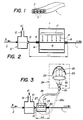
- Figure 1 illustrates a flat cable 1 of known type optical fibers, also called ribbon cable.
- it comprises four juxtaposed and parallel optical fibers 2, coated in a sheath 3 of synthetic material which maintains their relative positions and which protects them from external damage.
- the sheath may be made of thermoplastic material.
- the sheath 3 is made of a material whose hardness and toughness are increased by crosslinking with ultraviolet rays after the sheath has been shaped, for example an acrylate curable at ultraviolet radiation.
- FIG. 2 shows part of the installation for manufacturing such a cable 1 according to the prior art, in particular the elements of the installation used to form the sheath 3.
- These elements essentially comprise a head 10 constituting an applicator of synthetic material on the optical fibers 2, and a crosslinking furnace 11 serving to harden the synthetic material by a crosslinking initiated by means of ultraviolet radiation.
- the head 10 has a lateral inlet 12 through which the synthetic material is introduced under pressure along arrow A, and an outlet die 13 which shapes the sheath 3 around the fibers 2 driven continuously in the direction of arrow B.
- the oven 11 contains a crosslinking chamber 14 traversed longitudinally by the cable 1, which passes through the inlet 15 and outlet 16 heads of the furnace.
- the chamber 14 contains one or more ultraviolet lamps 17 and reflectors 18 which concentrate the radiation 19 of the lamp on the cable 1.
- the chamber 14 is provided with a ventilation circuit (not shown) to cool the lamp 17 as explained above.
- the sheath of the cable 1 is sufficiently hardened to be supported and driven longitudinally by suitable rollers, then the cable can be wound on a reel.
- one of the drawbacks of this installation is the relatively large length of the crosslinking chamber 14, so that the cable 1 must remain unsupported under a relatively long length L1 between the die 13 and the outlet. 16 of the oven 11, since in this manufacturing step contact with a support would deform the still soft sheath of the cable. In addition, the sheath undergoes in chamber 14 the undesirable thermal effects mentioned above.
- the application head 10 can be the same as in the previous example. Its die 13 is immediately followed by a crosslinking chamber 21 much smaller than the chamber 14, and in particular shorter, so that the length L2 traversed by the cable 1 between the die 13 and the outlet 22 of the chamber 21 represents only a fraction of the length L1. Indeed, the ultraviolet radiation 23 applied to the cable comes from a source 24 located outside of the chamber 21, via a light conductor 25 having an input 26 coupled to the source 24 and an output 27 located in the chamber 21 in the immediate vicinity of the cable 1. This outlet 27 may have an elongated shape having the dimensions desired to distribute the radiation over an appropriate length of the cable, with an appropriate intensity.
- the light conductor 25 is a bundle of optical fibers.
- the optical fibers can easily be arranged around the cable 1 so as to ensure the desired distribution of the radiation over the various external surfaces of the cable sheath.
- the outlet 27 of the cable can be located very close to the die 13, the chamber 21 even being able to be directly associated with the head 10.
- FIG. 4 shows a second embodiment of the installation according to the invention.
- This installation comprises first means 111 for bonding the fibers 2 arranged in parallel and in a coplanar manner, first means 112a and 112b for crosslinking by exposure to ultraviolet radiation the synthetic material used to bond said fibers, second means 113 for coating these fibers previously bonded, and second means 114a and 114b for ensuring the crosslinking of the synthetic material used to coat said fibers 2 and form the sheath 3.
- Said first means 111 for bonding the fibers comprise a chamber 115 provided with an inlet die 115a, an outlet die 115b and an inlet 116 of synthetic material 7 used for bonding the fibers arranged in parallel.
- the outlet die 115b has an opening which is substantially equal to the diameter of the fibers in such a way that the synthetic material 7 becomes encrusted between the fibers 2 (see FIG. 6) without forming any excess thickness relative to the thickness of the fiber sheet.
- the means 112a and 112b for crosslinking the synthetic material consist of sources, respectively 119a and 119b, generating ultraviolet rays, light conductors 120a and 120b and heads emitting ultraviolet radiation respectively 121a and 121b. It will be noted that these two heads are arranged in the immediate vicinity of the outlet die 115b, which allows almost instantaneous crosslinking of the synthetic material used to bond the fibers 2 together.
- the second means 113 for coating the sheet of fibers previously glued comprise a second chamber 122 equipped with an inlet die 122a and an outlet die 122b as well as an inlet 123 of synthetic material 8 represented by an arrow.
- the synthetic material 8 may be identical or different from the synthetic material 7 previously used to ensure the bonding of the fibers.
- the inlet die 122a has substantially the same geometry and the same dimensions as the outlet die 115b from the chamber 115 and the outlet die 122b has a geometry and dimensions which correspond to those of the flat cable 1 as represented by the figure 7.
- the reflecting surfaces 42 are mounted on supports 43 pivoting about an axis 44 and maintained in the working position by a tension spring 45.
- the reflecting surface can be tilted into a position 42 ′, shown in broken lines, by pivoting of the support 43 resulting in a stretching of the spring 45 which acts as a return spring.
Abstract
Description
La présente invention concerne un procédé de fabrication en continu d'un câble plat contenant plusieurs conducteurs parallèles, notamment des fibres optiques, noyés dans une gaine faite d'au moins une matière synthétique photoréticulée, ce procédé comportant au moins une étape, dite principale, consistant à appliquer une première matière synthétique photoréticulable autour de conducteurs disposés parallèlement les uns aux autres pour former une gaine, et à appliquer un premier rayonnement lumineux, notamment ultraviolet, à la gaine ainsi formée pour provoquer une réticulation de ladite première matière synthétique.The present invention relates to a continuous manufacturing process of a flat cable containing several parallel conductors, in particular optical fibers, embedded in a sheath made of at least one photocrosslinked synthetic material, this process comprising at least one step, called the main step, consisting in applying a first photocrosslinkable synthetic material around conductors arranged parallel to one another to form a sheath, and in applying a first light radiation, in particular ultraviolet, to the sheath thus formed to cause crosslinking of said first synthetic material.
L'invention concerne également une installation pour la mise en oeuvre de ce procédé pour la fabrication en continu d'un câble plat contenant plusieurs conducteurs parallèles, notamment des fibres optiques, noyés dans une gaine faite d'au moins une matière synthétique photoréticulée, cette installation comportant au moins une première tête d'application destinée à être traversée en continu par les conducteurs disposés parallèlement entre eux et pourvue d'au moins une filière pour appliquer une première matière synthétique photoréticulable autour des conducteurs pour former une gaine, au moins une première source de rayonnement lumineux, notamment ultraviolet, et au moins un premier dispositif de réticulation disposé sur la trajectoire du câble sortant de la filière et pour lequel ledit premier rayonnement lumineux est appliqué au câble pour réticuler ladite première matière synthétique.The invention also relates to an installation for implementing this method for the continuous manufacture of a flat cable containing several parallel conductors, in particular optical fibers, embedded in a sheath made of at least one photocrosslinked synthetic material, this installation comprising at least a first application head intended to be traversed continuously by the conductors arranged parallel to each other and provided with at least one die for applying a first photocrosslinkable synthetic material around the conductors to form a sheath, at least a first source of light radiation, in particular ultraviolet, and at least one first crosslinking device disposed on the path of the cable leaving the die and for which said first light radiation is applied to the cable to crosslink said first synthetic material.
Dans les installations actuelles de ce genre, dont on décrira des exemples de réalisation, le câble sortant de la filière traverse ensuite un four où l'on fait durcir au moins une partie de sa gaine. Ce four comporte une chambre de réticulation contenant une ou plusieurs lampes à rayonnement ultraviolet et des réflecteurs qui dirigent ce rayonnement vers le câble. Une telle chambre présente différents inconvénients pouvant se répercuter sur la qualité et la régularité de fabrication du câble. Un premier type d'inconvénient est créé par la longueur trop importante de cette chambre, due à la longueur des lampes nécessaires utilisées, qui provoque d'une part un amorçage du processus de réticulation et de stabilisation de la forme de la gaine relativement lent, de sorte que la gaine reste déformable sur une longueur relativement importante, et d'autre part une absence de guidage du câble dans cette zone, si bien qu'il peut subir des vibrations nuisibles. Un autre type d'inconvénient provient de la chaleur produite par les lampes, qui a tendance à échauffer excessivement la matière synthétique au cours de la polymérisation. Ces lampes sont généralement refroidies par ventilation, mais l'air de refroidissement peut aussi avoir des effets nuisibles sur le câble.In current installations of this kind, of which an embodiment will be described, the cable leaving the die then passes through an oven where at least part of its sheath is hardened. This oven has a crosslinking chamber containing one or more lamps with ultraviolet radiation and reflectors which direct this radiation towards the cable. Such a room has various drawbacks which can affect the quality and regularity of cable manufacturing. A first type of drawback is created by the excessively long length of this chamber, due to the length of the necessary lamps used, which causes on the one hand an initiation of the process of crosslinking and of stabilization of the shape of the relatively slow sheath, so that the sheath remains deformable over a relatively large length, and on the other hand a lack of guide of the cable in this zone, so that it can undergo harmful vibrations. Another type of disadvantage arises from the heat produced by the lamps, which tends to overheat the synthetic material during polymerization. These lamps are usually fan cooled, but the cooling air can also have harmful effects on the cable.
Enfin, pendant le court laps de temps qui s' écoule entre l'enrobage et la réticulation, la matière synthétique est molle et n'assure pas un maintien ferme des conducteurs parallèles entre eux et coplanaires. Il arrive par conséquent que ces conducteurs se déplacent les uns par rapport aux autres, ce qui altère les performances du câble.Finally, during the short time that elapses between the coating and the crosslinking, the synthetic material is soft and does not provide a firm hold of the conductors parallel to each other and coplanar. Consequently, these conductors sometimes move relative to each other, which degrades the performance of the cable.
La présente invention a pour but un procédé et une installation permettant d'éviter dans une large mesure les inconvénients mentionnés ci-dessus, et en particulier de stabiliser la gaine le plus vite possible dès sa sortie de la filière.The object of the present invention is to provide a method and an installation which make it possible to largely avoid the drawbacks mentioned above, and in particular to stabilize the sheath as soon as possible as soon as it leaves the die.
Dans ce but, l'invention concerne un procédé du type indiqué en préambule, caractérisé en ce que ledit premier rayonnement lumineux est appliqué à la gaine immédiatement après son formage et est transmis d'au moins une première source de rayonnement éloignée jusqu'à proximité immédiate de la gaine au moyen d'au moins un premier conducteur de lumière.For this purpose, the invention relates to a method of the type indicated in the preamble, characterized in that said first light radiation is applied to the sheath immediately after its formation and is transmitted from at least one first source of radiation distant to near immediate sheath by means of at least a first light conductor.
Ledit premier rayonnement lumineux peut avantageusement être distribué le long de la gaine grâce à une configuration allongée d'une sortie du premier conducteur de lumière.Said first light radiation can advantageously be distributed along the sheath thanks to an elongated configuration of an output of the first light conductor.
Le procédé peut en outre comprendre, préalablement à ladite étape principale de formation de la gaine, une étape préliminaire consistant à coller les conducteurs parallèlement entre eux, en appliquant une seconde matière synthétique photoréticulable entre ces conducteurs maintenus parallèlement entre eux et en réticulant cette seconde matière synthétique au moyen d'un second rayonnement lumineux, notamment ultraviolet, ladite étape principale de formation de la gaine consistant alors à enrober de ladite première matière synthétique lesdits conducteurs ainsi préalablement collés pour former ladite gaine, et à réticuler ladite première matière synthétique d'enrobage au moyen dudit premier rayonnement lumineux.The method can also comprise, prior to said step main sheath formation, a preliminary step consisting in bonding the conductors parallel to each other, by applying a second photocrosslinkable synthetic material between these conductors held parallel to each other and by crosslinking this second synthetic material by means of a second light radiation, in particular ultraviolet, said main step of forming the sheath then consisting in coating with said first synthetic material said conductors thus previously bonded to form said sheath, and in crosslinking said first synthetic coating material by means of said first light radiation.
De préférence l'on colle les conducteurs au moyen de la même matière synthétique que celle avec laquelle on les enrobe.Preferably, the conductors are glued using the same synthetic material as that with which they are coated.
De façon avantageuse, l'on effectue la réticulation de la seconde matière synthétique utilisée pour coller les conducteurs dans une zone adjacente à la zone d'application de cette seconde matière synthétique, et l'on effectue la réticulation de la première matière synthétique utilisée pour enrober les conducteurs préalablement collés dans une zone adjacente à la zone d'application de cette première matière synthétique. Cette réticulation s'effectue en irradiant simultanément les deux faces opposées de la gaine formée autour des conducteurs.Advantageously, the crosslinking of the second synthetic material used for bonding the conductors is carried out in an area adjacent to the zone of application of this second synthetic material, and the crosslinking of the first synthetic material used for coat the conductors previously glued in an area adjacent to the area of application of this first synthetic material. This crosslinking is carried out by simultaneously irradiating the two opposite faces of the sheath formed around the conductors.
Pour la mise en oeuvre de ce procédé une installation selon l'invention est caractérisée en ce que ladite première source de rayonnement lumineux est éloignée dudit premier dispositif de réticulation et comprend au moins un premier conducteur de lumière pour transmettre ledit rayonnement lumineux à proximité immédiate de la gaine et à la sortie immédiate de celle-ci de la filière.For the implementation of this method, an installation according to the invention is characterized in that said first source of light radiation is distant from said first crosslinking device and comprises at least a first light conductor for transmitting said light radiation in the immediate vicinity of the sheath and at its immediate exit from the die.
De préférence, ce premier dispositif de réticulation est adjacent à la filière de la première tête d'application et comporte une chambre de réticulation.Preferably, this first crosslinking device is adjacent to the die of the first application head and comprises a crosslinking chamber.
Le premier conducteur de lumière peut comporter un tube creux rempli d'un liquide conducteur de lumière ou comporter des fibres optiques en verre de silice ou être réalisé en une matière ayant une meilleure transparence au rayonnement ultraviolet qu'au rayonnement infrarouge de la source.The first light conductor may comprise a hollow tube filled with a light conductive liquid or may comprise optical fibers made of silica glass or be made of a material having better transparency to ultraviolet radiation than to infrared radiation from the source.
Dans toutes les formes de réalisation, le premier conducteur de lumière comporte, en regard du câble, une sortie de forme allongée s'étendant le long du câble.In all embodiments, the first light conductor comprises, facing the cable, an elongated outlet extending along the cable.
Selon une autre forme de réalisation particulièrement avantageuse, l'installation comporte en outre, en amont de ladite première tête d'application pour former ladite gaine, des moyens pour coller lesdits conducteurs parallèlement entre eux, lesdits moyens de collage comprenant une seconde tête d'application également traversée en continu par les conducteurs et pourvue d'au moins une filière, pour appliquer une seconde matière synthétique photoréticulable entre les conducteurs maintenus parallèles entre eux, et des moyens pour réticuler ladite seconde matière synthétique photoréticulable au moyen d'un second rayonnement lumineux.According to another particularly advantageous embodiment, the installation further comprises, upstream of said first application head for forming said sheath, means for bonding said conductors parallel to each other, said bonding means comprising a second head for application also continuously traversed by the conductors and provided with at least one die, for applying a second photocrosslinkable synthetic material between the conductors kept parallel to each other, and means for crosslinking said second photocrosslinkable synthetic material by means of a second light radiation .
De préférence, les moyens pour réticuler la seconde matière synthétique appliquée entre les conducteur comportent au moins une seconde source de rayonnement lumineux, notamment ultraviolet, agencée pour irradier cette seconde matière synthétique sur toutes ses faces. Cette seconde source de rayonnement lumineux peut être associée à une surface réfléchissante agencée pour concentrer le rayonnement sur la face du câble plat opposée à ladite source.Preferably, the means for crosslinking the second synthetic material applied between the conductors comprise at least one second source of light radiation, in particular ultraviolet, arranged to irradiate this second synthetic material on all of its faces. This second source of light radiation can be associated with a reflecting surface arranged to concentrate the radiation on the face of the flat cable opposite said source.
D'une façon avantageuse, les moyens pour réticuler respectivement la seconde et la première matière synthétique sont adjacents respectivement aux moyens pour appliquer la seconde matière synthétique entre les conducteurs et aux moyens pour enrober ces conducteurs de première matière synthétique.Advantageously, the means for crosslinking the second and the first synthetic material respectively are adjacent respectively to the means for applying the second synthetic material between the conductors and to the means for coating these conductors with first synthetic material.
Les moyens pour appliquer et pour réticuler ladite seconde matière synthétique servant au collage des conducteurs peuvent comporter un bloc optique unique dans lequel est ménagé un canal de guidage des conducteurs parallèlement entre eux, ce bloc étant associé à des systèmes optiques convergents pour focaliser le second rayonnement lumineux sur chacune des faces de la seconde matière synthétique utilisée pour coller ces conducteurs.The means for applying and for crosslinking said second synthetic material used for bonding the conductors may comprise a single optical unit in which is formed a channel for guiding the conductors parallel to each other, this block being associated with converging optical systems to focus the second light radiation on each of the faces of the second synthetic material used to bond these conductors.
De façon similaire, les moyens pour appliquer et pour réticuler ladite première matière synthétique d'enrobage des conducteurs préalablement collés peuvent comporter un bloc optique unique dans lequel est ménagé un canal de guidage des conducteurs collés, ce bloc étant associé à des systèmes optiques convergents pour focaliser le premier rayonnement lumineux sur chacune des faces de la première matière synthétique utilisée pour enrober les conducteurs collés.Similarly, the means for applying and for crosslinking said first synthetic material for coating the previously bonded conductors may comprise a single optical unit in which is formed a guide channel for the bonded conductors, this unit being associated with converging optical systems for focusing the first light radiation on each of the faces of the first synthetic material used to coat the bonded conductors.
Dans une forme de réalisation particulière, le bloc optique peut se composer de deux coquilles adjacentes qui définissent ensemble ledit canal de guidage.In a particular embodiment, the optical unit can consist of two adjacent shells which together define said guide channel.
La présente invention et ses avantages apparaîtront mieux dans la description suivante d'exemples de fabrication d'un câble plat à fibres optiques, respectivement selon l'art antérieur et selon l'invention, en référence aux dessins annexés, dans lesquels :
- la figure 1 est une vue en perspective et en coupe transversale d'un câble plat à fibres optiques pouvant être fabriqué par le procédé ci-dessus,
- la figure 2 est une vue schématique d'une installation de fabrication d'un tel câble selon l'art antérieur,
- la figure 3 est une vue schématique d'une première forme de réalisation d'une installation selon la présente invention,
- la figure 4 représente une vue schématique d'une deuxième forme de réalisation d'une installation selon l'invention,
- la figure 5 représente une vue en perspective, partiellement coupée d'un câble plat tel que réalisé selon les techniques connues et présentant un défaut évoqué ci-dessus,
- la figure 6 représente une vue en perspective du câble tel qu'il se présente après la première phase du procédé de l'invention,
- la figure 7 représente une vue en perspective du câble plat tel qu'il se présente après la mise en oeuvre du procédé de l'invention,
- la figure 8 représente une vue de dessus d'une réalisation préférée d'une station de réticulation par application d'un rayonnement ultraviolet,
- la figure 9 représente une vue de côté de la station de la figure 8, et
- la figure 10 représente une vue en perspective d'une variante particulièrement avantageuse d'une station de réticulation par application d'un rayonnement ultraviolet.
- FIG. 1 is a perspective view in cross section of a flat fiber optic cable which can be manufactured by the above method,
- FIG. 2 is a schematic view of an installation for manufacturing such a cable according to the prior art,
- FIG. 3 is a schematic view of a first embodiment of an installation according to the present invention,
- FIG. 4 represents a schematic view of a second embodiment of an installation according to the invention,
- FIG. 5 represents a perspective view, partially cut away of a flat cable as produced according to known techniques and having a defect mentioned above,
- FIG. 6 represents a perspective view of the cable as it appears after the first phase of the process of the invention,
- FIG. 7 represents a perspective view of the flat cable as it appears after the implementation of the method of the invention,
- FIG. 8 represents a top view of a preferred embodiment of a crosslinking station by application of ultraviolet radiation,
- FIG. 9 represents a side view of the station of FIG. 8, and
- FIG. 10 represents a perspective view of a particularly advantageous variant of a crosslinking station by application of ultraviolet radiation.
La figure 1 illustre un câble plat 1 à fibres optiques de type connu, appelé aussi câble en ruban. Dans cet exemple, il comprend quatre fibres optiques 2 juxtaposées et parallèles, enrobées dans une gaine 3 en matière synthétique qui maintient leurs positions relatives et qui les protège des dommages extérieurs. Dans certains cas, la gaine peut être en matière thermoplastique. Cependant, dans le type de câble concerné par la présente invention, la gaine 3 est faite d'une matière dont la dureté et la ténacité sont augmentées par réticulation aux rayons ultraviolets après la mise en forme de la gaine, par exemple un acrylate durcissable au rayonnement ultraviolet.Figure 1 illustrates a
La figure 2 montre une partie de l'installation pour la fabrication d'une tel câble 1 selon l'art antérieur, en particulier les éléments de l'installation servant à former la gaine 3. Ces éléments comprennent essentiellement une tête 10 constituant un applicateur de matière synthétique sur les fibres optiques 2, et un four de réticulation 11 servant à faire durcir la matière synthétique par une réticulation amorcée au moyen d'un rayonnement ultraviolet. La tête 10 a une entrée latérale 12 par où la matière synthétique est introduite sous pression suivant la flèche A, et une filière de sortie 13 qui façonne la gaine 3 autour des fibres 2 entraînées en continu dans le sens de la flèche B. Le four 11 contient une chambre de réticulation 14 traversée longitudinalement par le câble 1, lequel passe dans des têtes d'entrée 15 et de sortie 16 du four. La chambre 14 contient une ou plusieurs lampes à ultraviolet 17 et des réflecteurs 18 qui concentrent sur le câble 1 le rayonnement 19 de la lampe. La chambre 14 est pourvue d'un circuit de ventilation (non représenté) pour refroidir la lampe 17 comme expliqué plus haut. A la sortie 16 du four il, la gaine du câble 1 est suffisamment durcie pour être soutenue et entraînée longitudinalement par des rouleaux appropriés, puis le câble peut être enroulé sur une bobine.FIG. 2 shows part of the installation for manufacturing such a
Comme on l'a expliqué plus haut, un des inconvénients de cette installation est la longueur relativement importante de la chambre de réticulation 14, de sorte que le câble 1 doit rester non soutenu sous une longueur L₁ relativement grande entre la filière 13 et la sortie 16 du four 11, puisque dans cette étape de fabrication un contact avec un support déformerait la gaine encore molle du câble. De plus, la gaine subit dans la chambre 14 les effets thermiques indésirables mentionnés plus haut.As explained above, one of the drawbacks of this installation is the relatively large length of the
Ces inconvénients sont évités dans l'installation selon l'invention telle qu'illustrée par la figure 3. La tête d'application 10 peut être la même que dans l'exemple précédent. Sa filière 13 est suivie immédiatement d'une chambre de réticulation 21 beaucoup plus petite que la chambre 14, et en particulier plus courte, de sorte que la longueur L₂ parcourue par le câble 1 entre la filière 13 et la sortie 22 de la chambre 21 ne représente qu'une fraction de la longueur L₁. En effet, le rayonnement ultraviolet 23 appliqué au câble provient d'une source 24 située à l'extérieur de la chambre 21, par l'intermédiaire d'un conducteur de lumière 25 ayant une entrée 26 couplée à la source 24 et une sortie 27 située dans la chambre 21 à proximité immédiate du câble 1. Cette sortie 27 peut avoir une forme allongée ayant les dimensions voulues pour distribuer le rayonnement sur une longueur appropriée du câble, avec une intensité appropriée. Comme la distance entre la source 24 et la chambre 21 peut être variable, le conducteur de lumière 25 peut être choisi parmi des conducteurs de différentes natures, par exemple des conducteurs à eau ou des faisceaux de fibres optiques. Afin de limiter le rayonnement thermique appliqué au câble 1, on pourra choisir un conducteur fait d'une matière ayant une bonne transmission du rayonnement ultraviolet dans la bande concernée, mais une transmission relativement médiocre des rayonnements infrarouges, par exemple un conducteur à eau.These drawbacks are avoided in the installation according to the invention as illustrated in FIG. 3. The
Dans le cas présent, le conducteur de lumière 25 est un faisceau de fibres optiques. A titre d'exemple, on a représenté en traits interrompus un faisceau supplémentaire 25a provenant de la même source 24 et conduisant le rayonnement ultraviolet vers une face opposée du câble plat 1. On conçoit que les fibres optiques peuvent aisément être disposées autour du câble 1 de façon à assurer la distribution voulue du rayonnement sur les différentes surfaces extérieures de la gaine du câble. De plus, la sortie 27 du câble peut être située tout près de la filière 13, la chambre 21 pouvant même être associée directement à la tête 10.In the present case, the
La source 24 comporte une ou plusieurs lampes 28 émettant le rayonnement ultraviolet 23. Cette lampe peut être allongée, du même type que la lampe 17 de l'exemple précédent. Un réflecteur 29 concentre le rayonnement 23 sur un condenseur formé de deux lentilles 30 et 31 qui focalisent le rayonnement sur l'entrée 26 du conducteur à fibres optiques 25. Cependant, l'utilisation d'un conducteur de lumière permet de choisir n'importe quel type de source 24 de rayonnement ultraviolet, quel que soit son encombrement. Par ailleurs, le refroidissement par ventilation de la source 24 ne touche absolument pas le câble 1.The
Comme la longueur L₂ entre la filière et la sortie de la chambre de réticulation est plus faible que dans l'art antérieur, le câble peut être soutenu plus près de sa sortie de la filière 13 et subit moins de vibrations ou d'autres effets mécaniques, ce qui garantit une meilleure qualité géométrique du câble et une meilleure liaison entre les fibres optiques 2 et la matrice de matière synthétique formant la gaine 3.As the length L₂ between the die and the outlet of the crosslinking chamber is shorter than in the prior art, the cable can be supported closer to its outlet from the
La figure 4, représente une seconde forme de réalisation de l'installation selon l'invention. Cette installation comporte des premiers moyens 111 pour coller les fibres 2 disposées parallèlement et d'une manière coplanaire, des premiers moyens 112a et 112b pour assurer la réticulation par exposition à un rayonnement ultraviolet de la matière synthétique utilisée pour assurer le collage desdites fibres, des seconds moyens 113 pour enrober ces fibres préalablement collées, et des seconds moyens 114a et 114b pour assurer la réticulation de la matière synthétique utilisée pour enrober lesdites fibres 2 et former la gaine 3.Figure 4 shows a second embodiment of the installation according to the invention. This installation comprises first means 111 for bonding the
Lesdits premiers moyens 111 pour coller les fibres comportent une chambre 115 pourvue d'une filière d'entrée 115a, d'une filière de sortie 115b et d'une arrivée 116 de matière synthétique 7 utilisée pour assurer le collage des fibres disposées parallèlement. A cet effet, la filière de sortie 115b présente une ouverture qui est sensiblement égale au diamètre des fibres de telle manière que la matière synthétique 7 vienne s'incruster entre les fibres 2 (voir figure 6) sans former aucune surépaisseur par rapport à l'épaisseur de la nappe de fibres .Said first means 111 for bonding the fibers comprise a
Les moyens 112a et 112b pour réticuler la matière synthétique, appelés stations de réticulation, se composent de sources, respectivement 119a et 119b, génératrices de rayons ultraviolets, de conducteurs de lumières 120a et 120b et de têtes émettrices de rayonnements ultraviolets respectivement 121a et 121b. On notera que ces deux têtes sont disposées à proximité immédiate de la filière de sortie 115b, ce qui permet une réticulation quasi instantanée de la matière synthétique ayant servi à coller les fibres 2 entre elles. Comme cette réticulation s'effectue immédiatement à la sortie de la chambre 115, les fibres qui sont positionnées de façon à être parallèles entre elles et coplanaires par la géométrie même de la filière de sortie 115b, sont maintenues et figées dans cette position grâce à l'opération de réticulation qui s'effectue dans cette zone adjacente à la filière de sortie de la chambre 115.The means 112a and 112b for crosslinking the synthetic material, called crosslinking stations, consist of sources, respectively 119a and 119b, generating ultraviolet rays,
A titre de comparaison, la figure 5 montre la position quelque peu désordonnée des fibres 2 obtenue selon les techniques de l'art antérieur, c'est-à-dire lorsque l'on n'effectue pas le collage des fibres 2 telles que représentées par la figure 6 antérieurement à l'enrobage de la nappe ainsi réalisée pour obtenir un câble plat tel que représenté par la figure 7.By way of comparison, FIG. 5 shows the somewhat disordered position of the
Les seconds moyens 113 pour enrober la nappe de fibres préalablement encollées comportent une seconde chambre 122 équipée d'une filière d'entrée 122a et d'une filière de sortie 122b ainsi que d'une arrivée 123 de matière synthétique 8 représentée par une flèche. On notera que la matière synthétique 8 peut être identique ou différente de la matière synthétique 7 préalablement utilisée pour assurer le collage des fibres. La filière d'entrée 122a a sensiblement la même géométrie et les mêmes dimensions que la filière de sortie 115b de la chambre 115 et la filière de sortie 122b a une géométrie et des dimensions qui correspondent à celles du câble plat 1 tel que représenté par la figure 7.The second means 113 for coating the sheet of fibers previously glued comprise a
Les moyens pour réticuler la matière synthétique, respectivement 114a et 114b, appelés stations de réticulation de la matière synthétique d' enrobage 8, comportent une ou plusieurs sources, respectivement 125a et 125b, génératrices de rayonnements ultraviolets, des conducteurs de lumière, respectivement 126a et 126b, et des têtes d'application respectivement 127a et 127b. Ces têtes d'application ainsi que les têtes d'application 121a et 121b des moyens d'encollage des fibres seront décrites plus en détail en référence aux figures 8 et 9.The means for crosslinking the synthetic material, respectively 114a and 114b, called crosslinking stations for the
Comme le montre la figure 7, le câble plat 1 obtenu grâce à l'installation illustrée schématiquement par la figure 4 comporte un ensemble de fibres 2 parallèles et coplanaires enrobées dans une couche de matière synthétique 8 après avoir été préencollées au moyen de la matière synthétique 7. Selon un mode de réalisation préféré, les deux matières synthétiques 7 et 8 sont identiques de sorte que les deux substances ayant été utilisées respectivement pour coller les fibres et pour les enrober sont intimement liées et se confondent pour former la gaine 3 du câble 1 tel que représenté en figure 1.As shown in FIG. 7, the
En conclusion, l'étape d'encollage des conducteurs, notamment des conducteurs de lumière et plus particulièrement des fibres optiques, permet d'assurer une disposition régulière et coplanaire de ces composants et d' éviter leur positionnement plus ou moins aléatoire à l'intérieur de la masse d'enrobage.In conclusion, the step of gluing conductors, in particular light conductors and more particularly optical fibers, makes it possible to ensure a regular and coplanar arrangement of these components and to avoid their more or less random positioning inside. of the coating mass.
En référence aux figures 8 et 9, les moyens destinés à assurer la réticulation des matières synthétiques 7 et/ou 8 comportent de préférence plusieurs têtes d'application d'un rayonnement ultraviolet.With reference to FIGS. 8 and 9, the means intended to ensure the crosslinking of the
Chacune de ces têtes comporte un élément cylindrique 40 réalisé en une matière transparente aux rayons ultraviolets, telle que par exemple le quartz, qui constitue un conducteur de lumière couplé à un conducteur flexible 41 constitué par exemple par un tube creux souple rempli d'un liquide tel que l'eau, ce tube étant connecté à une source émettrice de rayons ultraviolets (non représentée). En regard de l'extrémité 40 du conducteur de lumière est montée une surface réfléchissante 42 ayant de préférence une forme parabolique dont le but est de réfléchir une partie du rayonnement ultraviolet émis par le tronçon d'extrémité 46 du conducteur de lumière 40 afin d'irradier la matière synthétique de collage ou d'enrobage des fibres parallèles, sur toutes leurs faces.Each of these heads comprises a
Plusieurs têtes d'application du rayonnement peuvent être prévues afin d'accélérer le processus de réticulation et d'assurer un positionnement quasi parfait des fibres à l'intérieur de la couche de matière synthétique. On notera que ces moyens de réticulation sont disposés à proximité immédiate de la filière d'évacuation 115b ou 122b définie ci-dessus.Several radiation application heads can be provided in order to speed up the crosslinking process and to ensure an almost perfect positioning of the fibers inside the layer of synthetic material. It will be noted that these crosslinking means are arranged in the immediate vicinity of the discharge die 115b or 122b defined above.
Comme le montre la figure 9, les surfaces réfléchissantes 42 sont montées sur des supports 43 pivotant autour d'un axe 44 et maintenus en position de travail par un ressort de traction 45. Toutefois, pour faciliter l'accès à la zone de traitement, la surface réfléchissante peut être basculée dans une position 42′, représentée en traits interrompus, par pivotement du support 43 entraînant un étirement du ressort 45 qui fait office de ressort de rappel.As shown in FIG. 9, the reflecting
Cette construction est particulièrement avantageuse en ce qu'elle permet une réalisation compacte pouvant être placée immédiatement à la sortie des filières définies ci-dessus à proximité immédiate des zones d'encollage et/ou d'enrobage des fibres.This construction is particularly advantageous in that it allows a compact embodiment which can be placed immediately at the outlet of the dies defined above in the immediate vicinity of the sizing and / or coating areas of the fibers.
La figure 10 représente une forme de réalisation d'une station de réticulation qui présente des avantages particulièrement intéressants par rapport aux solutions décrites ci-dessus. Il est à noter que ces solutions tendent toutes à placer les stations de réticulation aussi près que possible des filières correspondantes pour éviter que les fibres ne puissent se déplacer les unes relativement aux autres pendant le laps de temps qui s' écoule entre le moment où elles sortent de la filière et celui où elles sont figées en position grâce à la réticulation de la matière synthétique. Dans la réalisation décrite ci-dessous, ce laps de temps est réduit au minimum grâce au fait que la fonction d'application de matière synthétique soit pour coller les fibres, soit pour les enrober lorsqu'elles ont été préalablement collées, et la fonction de réticulation par application d'un rayonnement ultraviolet sont assurées par un même bloc optique, par exemple en quartz, qui sert de filière et de diffuseur de rayons ultraviolets. Ce bloc optique 50 se compose de deux coquilles 51 et 52 qui comportent chacune un évidement 51a et 52a qui, lorsque les coquilles sont juxtaposées, définit un canal dont les dimensions sont celles des fibres accolées ou du câble plat de telle manière que ces fibres soient guidées pendant leur passage dans ce canal. Ce bloc est associé à une pièce 53 qui contient une chambre 54 contenant la matière synthétique. Par ailleurs, chacune des coquilles est associée à une lentille convergente, respectivement 55 et 56, qui focalise sur la face de la coquille correspondante, respectivement 57 et 58, en forme de lentille convergente, les rayons ultraviolets transmis par des conducteurs de lumière 59 et 60. La transmission de ces rayons est de ce fait optimale dans une zone, ce qui élimine quasiment toute possibilité de déplacement relatif des fibres.FIG. 10 represents an embodiment of a crosslinking station which has particularly advantageous advantages compared to the solutions described above. It should be noted that these solutions all tend to place the crosslinking stations as close as possible to the corresponding dies to prevent the fibers from being able to move relative to one another during the period of time which elapses between the time when they leave the die and that when they are fixed in position thanks to the crosslinking of the synthetic material. In the embodiment described below, this period of time is reduced to a minimum thanks to the fact that the function of applying synthetic material is either to bond the fibers, or to coat them when they have been previously bonded, and the function of crosslinking by application of ultraviolet radiation are ensured by the same optical unit, for example made of quartz, which serves as a die and a diffuser for ultraviolet rays. This
Les techniques de fabrication décrites dans le cadre de la présente invention sont aussi applicables à des câbles comportant des conducteurs électriques ou similaires à la place des fibres optiques ou en plus de ces fibres.The manufacturing techniques described in the context of the present invention are also applicable to cables comprising electrical conductors or the like in place of or in addition to optical fibers.
Claims (20)
- Method for continuously manufacturing flat cable (1) containing several parallel conductors (2), specifically optical fibers, encased in a duct (3; 8) made of at least one photo-cross linked synthetic material, said method comprising at least one phase, said principal phase, consisting of applying a first photo-cross linked synthetic material (3; 8) around the conductors (2) disposed in parallel to one another to form a duct, and of applying a first light radiation (23), specifically ultraviolet radiation, to the duct such as formed to cause a cross linking of the said first synthetic material, characterized in that said first light radiation is applied to the duct immediately after it is formed and is transmitted from at least a first separate radiation source (28; 125a, 125b) to the immediate proximity of the duct by means of at least a first light conductor (25, 25a; 126a, 126b; 59, 60).
- Method according to claim 1, characterized in that said first light radiation (23) is distributed along the duct by virtue of the elongate configuration of one output of the first light conductor (25, 25a; 126a, 126b; 59, 60)
- Method according to claim 1, characterized in that it moreover comprises, before said principal phase of forming the duct, a preliminary phase consisting of gluing the conductors (2) in parallel to one another, by applying a second photo-cross linked synthetic material (7) between these conductors kept in parallel to one another and of cross linking this second synthetic material by means of a second light radiation (112a, 112b), specifically ultraviolet radiation, said principal phase of forming the duct consisting of coating said previously glued conductors with said first synthetic material (3; 8) to form said duct, and of cross linking said first coating synthetic material by means of said first light radiation (28; 125a, 125b).
- Method according to claim 3, characterized in that the conductors (2) are glued with the same synthetic material as that which coats them.
- Method according to claim 3, characterized in that cross linking of the second synthetic material (7) used to glue the conductors takes place in an area adjacent the area (115) where this second synthetic material is applied, and in that cross linking of the first synthetic material (3; 8) used to coat the previously glued conductors takes place in an area adjacent the area (122) where this first synthetic material is applied.
- Method according to claim 1, characterized in that cross linking is accomplished by simultaneously irradiating the two opposite surfaces of the duct (3; 8) formed around the conductors (2).
- Equipment for implementing the method according to claim 1, for continuously manufacturing flat cable (1) containing several parallel conductors (2), specifically optical fibers, encased in a duct (3; 8) made of at least one photo-cross linked synthetic material, this equipment comprising at least a first applicator head (10; 113; 54) designed to be continuously traversed by the conductors (2) disposed in parallel to one another and having at least one die (13; 122b) to apply a first photo-cross linked synthetic material (3; 8) around the conductors to form a duct, at least a first light radiation source (28; 125a, 125b), specifically ultraviolet radiation, and at least a first cross linking device (21) located on the trajectory of the cable exiting of the die (13, 122b) and through which said first light radiation is applied to the cable for cross linking said first synthetic material, characterized in that said first light radiation source (28; 125a, 125b) is separate form said first cross linking device and comprises at least a first light conductor (25, 25a; 126a, 126b; 59, 60) for transmitting said light radiation to the immediate proximity of the duct and to the immediate exit of the duct of the die (13; 122b).
- Equipment according to the claim 7, characterized in that the first cross linking device (21) is adjacent the die (13; 122b) of the first applicator head (10; 113; 54).
- Equipment according to the claim 8, characterized in that the first cross linking device comprise a cross linking chamber (21).
- Equipment according to the claim 7, characterized in that the first light conductor (25, 25a; 126a, 126b) comprises a hollow tube filled with light conducting liquid.
- Equipment according to the claim 7, characterized in that the first light conductor (25, 25a; 126a, 126b) comprises silicon glass optical fibers.
- Equipment according to the claim 7, characterized in that the first light conductor (25, 25a; 126a, 126b) is made of a material more highly transparent to the ultraviolet radiation than to the infrared radiation emitted by the source.
- Equipment according to the claim 7, characterized in that the first light conductor (25, 25a; 126a, 126b) comprises an elongate output (27) across from the cable (1), and extending the length of the cable.
- Equipment according to the claim 7, characterized in that it moreover comprises, above said first applicator head (10; 113; 54) to form said duct, means for gluing said conductors (2) in parallel to one another, said means of gluing comprising a second applicator head also continuously traversed by the conductors and provided with at least one die (115b), to apply a second photo-cross linked synthetic material (7) between the conductors maintained parallel to one another, and means for cross linking said second photo-cross linked synthetic material (7) by means of a second light radiation (112a, 112b).
- Equipment according to the claim 14, characterized in that the means for cross linking the second synthetic material (7) comprises at least a second light radiation source (119a, 119b), specifically ultraviolet radiation, designed to irradiate every surface of said second synthetic material.
- Equipment according to the claim 15, characterized in that said second light radiation source (119a, 119b) is associated with a reflective surface (42) designed to concentrate the beam on the surface of the flat cable which is opposite said source.
- Equipment according to the claim 14, characterized in that the means (112a, 112b; 114a, 114b) to cross link respectively the second (7) and the first (3; 8) synthetic material, are respectively adjacent the means (115) for applying the second synthetic material (7) between the conductors and means (122) for coating these conductors with said first synthetic material (3; 8).
- Equipment according to the claim 14, characterized in that the means for applying and for cross linking said second synthetic material (7) used for the gluing of the conductors comprises a sole optical bench (50) with a passageway inside for maintaining the conductors parallel to one another, this bench being associated with converging optical systems (55, 56) for focusing the second light radiation onto each surface of the second synthetic material used to glue these conductors.
- Equipment according to the claim 14, characterized in that the means for applying and for cross linking said first synthetic material used for the coating of the conductors previously glued comprises a sole optical bench (50) with a passageway inside for maintaining the glued conductors, this bench being associated with converging optical systems for focusing the first light radiation onto each surface of the first synthetic material used to coat the glued conductors.
- Equipment according to anyone of the claims 18 or 19, characterized in that the optical bench is composed of two adjacent protuberances (51, 52) which together define the said guide passageway.
Applications Claiming Priority (5)
| Application Number | Priority Date | Filing Date | Title |
|---|---|---|---|
| FR9105032A FR2675621B1 (en) | 1991-04-19 | 1991-04-19 | PROCESS AND INSTALLATION FOR THE MANUFACTURE OF A FLAT CABLE, PARTICULARLY WITH OPTICAL FIBERS. |
| FR9105032 | 1991-04-19 | ||
| FR9115055 | 1991-12-02 | ||
| FR9115055A FR2684328A1 (en) | 1991-12-02 | 1991-12-02 | Method and device for manufacturing a flat cable comprising parallel conductors: light conductors, optical fibres |
| PCT/CH1992/000075 WO1992018892A1 (en) | 1991-04-19 | 1992-04-21 | Method and equipment for continuously producing a flat cable, particularly an optical fibre cable |
Publications (2)
| Publication Number | Publication Date |
|---|---|
| EP0535199A1 EP0535199A1 (en) | 1993-04-07 |
| EP0535199B1 true EP0535199B1 (en) | 1995-12-13 |
Family
ID=26228649
Family Applications (1)
| Application Number | Title | Priority Date | Filing Date |
|---|---|---|---|
| EP92908580A Expired - Lifetime EP0535199B1 (en) | 1991-04-19 | 1992-04-21 | Method and equipment for continuously producing a flat cable, particularly an optical fibre cable |
Country Status (6)
| Country | Link |
|---|---|
| EP (1) | EP0535199B1 (en) |
| JP (1) | JPH05509422A (en) |
| AT (1) | ATE131627T1 (en) |
| CA (1) | CA2085991A1 (en) |
| DE (1) | DE69206741T2 (en) |
| WO (1) | WO1992018892A1 (en) |
Families Citing this family (4)
| Publication number | Priority date | Publication date | Assignee | Title |
|---|---|---|---|---|
| CA2129397C (en) * | 1993-12-21 | 2005-03-22 | Mujibar M. Rahman | Process for manufacturing optical fiber ribbons |
| FR2725797B1 (en) * | 1994-10-13 | 1997-01-03 | Alcatel Cable | PROCESS FOR COATING A TAPE OF OPTICAL FIBERS BY MEANS OF A RESIN, AND DEVICE FOR IMPLEMENTING SUCH A PROCESS |
| FR2727212B1 (en) * | 1994-11-21 | 1997-01-03 | Alcatel Cable | METHOD FOR MANUFACTURING A CYLINDRICAL FIBER OPTIC MODULE |
| FR2766279B1 (en) * | 1997-07-17 | 1999-09-24 | Alsthom Cge Alcatel | PROCESS FOR MANUFACTURING OPTICAL FIBER TAPES |
Family Cites Families (13)
| Publication number | Priority date | Publication date | Assignee | Title |
|---|---|---|---|---|
| DE2459844A1 (en) * | 1974-12-18 | 1976-07-01 | Felten & Guilleaume Kabelwerk | Multi-core telephone cable - has profiled strand with grooves and upstanding ribs between which are secured metal cores |
| US4198554A (en) * | 1977-07-01 | 1980-04-15 | Cober Electronics, Inc. | Method and apparatus for microwave vulcanization of extruded rubber profiles |
| US4277642A (en) * | 1978-09-15 | 1981-07-07 | Western Electric Company, Inc. | Cordage having a plurality of conductors in a partitioned jacket |
| NL7908966A (en) * | 1979-12-13 | 1981-07-16 | Philips Nv | OPTICAL TELECOMMUNICATIONS ELEMENT, METHOD FOR MANUFACTURING IT AND OPTICAL TELECOMMUNICATIONS CABLE FITTED WITH THE ELEMENT. |
| DE3377299D1 (en) * | 1982-09-23 | 1988-08-11 | Bicc Plc | Method of manufacturing an optical fibre ribbon structure |
| US4709984A (en) * | 1984-08-02 | 1987-12-01 | Siemens Aktiengesellschaft | Ribbon-shaped transmission element and method of manufacture |
| FR2577796B1 (en) * | 1985-02-28 | 1987-06-19 | Touati Bernard | FIXING OF RIGID PARTS SUCH AS A DENTAL PROSTHESIS |
| US4861621A (en) * | 1987-04-27 | 1989-08-29 | Toyo Boseki Kabushiki Kaisha | Pultrusion with cure by ultraviolet radiation |
| DE3717852C2 (en) * | 1987-05-27 | 1996-02-29 | Siemens Ag | Process for the production of an optical fiber |
| DE3744465C1 (en) * | 1987-12-23 | 1989-02-09 | Siemens Ag | Device and method for producing the insulation layer of a line |
| DE3833406A1 (en) * | 1988-10-01 | 1990-04-05 | Kroenert Max Maschf | Process and apparatus for irradiating materials provided with coating substances |
| CH679844A5 (en) * | 1989-07-19 | 1992-04-30 | Emil Kuehne | |
| EP0438668A3 (en) * | 1990-01-26 | 1992-04-22 | Siemens Aktiengesellschaft | Manufacturing process for optical fibre ribbon and apparatus for carrying out said process |
-
1992
- 1992-04-21 AT AT92908580T patent/ATE131627T1/en not_active IP Right Cessation
- 1992-04-21 JP JP4507930A patent/JPH05509422A/en active Pending
- 1992-04-21 DE DE69206741T patent/DE69206741T2/en not_active Expired - Fee Related
- 1992-04-21 EP EP92908580A patent/EP0535199B1/en not_active Expired - Lifetime
- 1992-04-21 WO PCT/CH1992/000075 patent/WO1992018892A1/en active IP Right Grant
- 1992-04-21 CA CA002085991A patent/CA2085991A1/en not_active Abandoned
Also Published As
| Publication number | Publication date |
|---|---|
| WO1992018892A1 (en) | 1992-10-29 |
| JPH05509422A (en) | 1993-12-22 |
| EP0535199A1 (en) | 1993-04-07 |
| ATE131627T1 (en) | 1995-12-15 |
| DE69206741T2 (en) | 1996-08-14 |
| DE69206741D1 (en) | 1996-01-25 |
| CA2085991A1 (en) | 1992-10-20 |
Similar Documents
| Publication | Publication Date | Title |
|---|---|---|
| EP0121482B1 (en) | Wavelength multiplexer-demultiplexer and method of producing such an assembly | |
| EP0910772B1 (en) | Electromagnetic radiation transmitter/reflector device, apparatus and method therefor | |
| FR2727212A1 (en) | PROCESS FOR PRODUCING A CYLINDRICAL MODULE OF OPTICAL FIBERS | |
| FR2591717A1 (en) | LIGHT SOURCE DEVICE, IN PARTICULAR FOR MANAGEMENT OR OFFICE MACHINE | |
| EP0733923A1 (en) | Light generator for optical fibres | |
| FR2564982A1 (en) | COUPLING PIPE FROM A LIGHT GUIDE TO A LIGHT SOURCE, IN PARTICULAR FOR INTEGRATED CITY LIGHTING TO A MOTOR PROJECTOR ASSEMBLY | |
| EP0703480A1 (en) | Fibre optical cable and device for its fabrication | |
| CA1096215A (en) | No translation available | |
| EP0115765B1 (en) | Commutation switch for an optical waveguide circuit | |
| EP0535199B1 (en) | Method and equipment for continuously producing a flat cable, particularly an optical fibre cable | |
| FR2698180A1 (en) | Optical fiber splice holder for ribbed fiber optic cords. | |
| EP0706871A1 (en) | Coating process for a fiber optic tape with a resin and apparatus for performing this process | |
| FR2629219A1 (en) | OPTICAL FIBER COUPLER IN STAR AND ACTIVE TYPE | |
| FR2796129A1 (en) | LIGHTING ASSEMBLY FOR VEHICLES, EQUIPPED WITH A LIGHT GUIDED SYSTEM | |
| FR2834565A1 (en) | DEVICE FOR ENTERING AND / OR EXTINGUISHING OPTICAL SIGNALS INTO A LIGHT WAVEGUIDE | |
| EP0633424B1 (en) | Fiber optics light source arrangement with steerable light beam | |
| US6496620B1 (en) | Method and apparatus for improving power handling capabilities of polymer fibers | |
| EP0943946A1 (en) | Manufacturing method for a multiribbon of optical fibres separable in at least two ribbons of optical fibres | |
| FR2684328A1 (en) | Method and device for manufacturing a flat cable comprising parallel conductors: light conductors, optical fibres | |
| EP0855721B1 (en) | Fibre optical cable | |
| EP0286475B1 (en) | Method of modification of the reflection coefficient of the extremity of a monomode fibre and fibre interferometer fabricated using such method | |
| FR2675621A1 (en) | Process and installation for the manufacture of a flat cable, especially a fibre-optic flat cable | |
| WO2022223911A1 (en) | Method for preparing optical fibres with lateral light emission and installation for implementing same | |
| FR2488698A1 (en) | Assembly process for optical fibre cables - uses carrier with groove of width greater than dia. of cable and having depth greater than or equal to dia. | |
| KR100653573B1 (en) | variable optical attenuator |
Legal Events
| Date | Code | Title | Description |
|---|---|---|---|
| PUAI | Public reference made under article 153(3) epc to a published international application that has entered the european phase |
Free format text: ORIGINAL CODE: 0009012 |
|
| 17P | Request for examination filed |
Effective date: 19921228 |
|
| AK | Designated contracting states |
Kind code of ref document: A1 Designated state(s): AT CH DE ES FR GB IT LI SE |
|
| 17Q | First examination report despatched |
Effective date: 19941216 |
|
| GRAA | (expected) grant |
Free format text: ORIGINAL CODE: 0009210 |
|
| AK | Designated contracting states |
Kind code of ref document: B1 Designated state(s): AT CH DE ES FR GB IT LI SE |
|
| PG25 | Lapsed in a contracting state [announced via postgrant information from national office to epo] |
Ref country code: ES Free format text: THE PATENT HAS BEEN ANNULLED BY A DECISION OF A NATIONAL AUTHORITY Effective date: 19951213 |
|
| REF | Corresponds to: |
Ref document number: 131627 Country of ref document: AT Date of ref document: 19951215 Kind code of ref document: T |
|
| REF | Corresponds to: |
Ref document number: 69206741 Country of ref document: DE Date of ref document: 19960125 |
|
| REG | Reference to a national code |
Ref country code: CH Ref legal event code: NV Representative=s name: CABINET ROLAND NITHARDT CONSEILS EN PROPRIETE INDU |
|
| ITF | It: translation for a ep patent filed |
Owner name: DOTT. FRANCO CICOGNA |
|
| GBT | Gb: translation of ep patent filed (gb section 77(6)(a)/1977) |
Effective date: 19960306 |
|
| PLBE | No opposition filed within time limit |
Free format text: ORIGINAL CODE: 0009261 |
|
| STAA | Information on the status of an ep patent application or granted ep patent |
Free format text: STATUS: NO OPPOSITION FILED WITHIN TIME LIMIT |
|
| 26N | No opposition filed | ||
| PGFP | Annual fee paid to national office [announced via postgrant information from national office to epo] |
Ref country code: SE Payment date: 19990331 Year of fee payment: 8 |
|
| PGFP | Annual fee paid to national office [announced via postgrant information from national office to epo] |
Ref country code: FR Payment date: 19990423 Year of fee payment: 8 |
|
| PGFP | Annual fee paid to national office [announced via postgrant information from national office to epo] |
Ref country code: DE Payment date: 20000418 Year of fee payment: 9 |
|
| PGFP | Annual fee paid to national office [announced via postgrant information from national office to epo] |
Ref country code: GB Payment date: 20000419 Year of fee payment: 9 |
|
| PG25 | Lapsed in a contracting state [announced via postgrant information from national office to epo] |
Ref country code: SE Free format text: LAPSE BECAUSE OF NON-PAYMENT OF DUE FEES Effective date: 20000422 |
|
| PGFP | Annual fee paid to national office [announced via postgrant information from national office to epo] |
Ref country code: AT Payment date: 20000428 Year of fee payment: 9 |
|
| PGFP | Annual fee paid to national office [announced via postgrant information from national office to epo] |
Ref country code: CH Payment date: 20000711 Year of fee payment: 9 |
|
| EUG | Se: european patent has lapsed |
Ref document number: 92908580.1 |
|
| PG25 | Lapsed in a contracting state [announced via postgrant information from national office to epo] |
Ref country code: FR Free format text: LAPSE BECAUSE OF NON-PAYMENT OF DUE FEES Effective date: 20001229 |
|
| REG | Reference to a national code |
Ref country code: FR Ref legal event code: ST |
|
| PG25 | Lapsed in a contracting state [announced via postgrant information from national office to epo] |
Ref country code: GB Free format text: LAPSE BECAUSE OF NON-PAYMENT OF DUE FEES Effective date: 20010421 Ref country code: AT Free format text: LAPSE BECAUSE OF NON-PAYMENT OF DUE FEES Effective date: 20010421 |
|
| PG25 | Lapsed in a contracting state [announced via postgrant information from national office to epo] |
Ref country code: LI Free format text: LAPSE BECAUSE OF NON-PAYMENT OF DUE FEES Effective date: 20010520 Ref country code: CH Free format text: LAPSE BECAUSE OF NON-PAYMENT OF DUE FEES Effective date: 20010520 |
|
| GBPC | Gb: european patent ceased through non-payment of renewal fee |
Effective date: 20010421 |
|
| REG | Reference to a national code |
Ref country code: CH Ref legal event code: PL |
|
| PG25 | Lapsed in a contracting state [announced via postgrant information from national office to epo] |
Ref country code: DE Free format text: LAPSE BECAUSE OF NON-PAYMENT OF DUE FEES Effective date: 20020201 |
|
| PG25 | Lapsed in a contracting state [announced via postgrant information from national office to epo] |
Ref country code: IT Free format text: LAPSE BECAUSE OF NON-PAYMENT OF DUE FEES;WARNING: LAPSES OF ITALIAN PATENTS WITH EFFECTIVE DATE BEFORE 2007 MAY HAVE OCCURRED AT ANY TIME BEFORE 2007. THE CORRECT EFFECTIVE DATE MAY BE DIFFERENT FROM THE ONE RECORDED. Effective date: 20050421 |