EP0534998B1 - Brake lining temperature prediction for a traction control system - Google Patents
Brake lining temperature prediction for a traction control system Download PDFInfo
- Publication number
- EP0534998B1 EP0534998B1 EP91909584A EP91909584A EP0534998B1 EP 0534998 B1 EP0534998 B1 EP 0534998B1 EP 91909584 A EP91909584 A EP 91909584A EP 91909584 A EP91909584 A EP 91909584A EP 0534998 B1 EP0534998 B1 EP 0534998B1
- Authority
- EP
- European Patent Office
- Prior art keywords
- brake
- temperature
- braking
- control system
- temperature prediction
- Prior art date
- Legal status (The legal status is an assumption and is not a legal conclusion. Google has not performed a legal analysis and makes no representation as to the accuracy of the status listed.)
- Expired - Lifetime
Links
- 230000003044 adaptive effect Effects 0.000 claims abstract description 34
- 238000001816 cooling Methods 0.000 claims description 28
- 238000010438 heat treatment Methods 0.000 claims description 23
- 238000004364 calculation method Methods 0.000 claims description 16
- 238000000034 method Methods 0.000 claims description 15
- 241000269627 Amphiuma means Species 0.000 claims description 2
- 230000000694 effects Effects 0.000 claims description 2
- 239000012530 fluid Substances 0.000 claims description 2
- 230000007246 mechanism Effects 0.000 abstract description 4
- 238000010586 diagram Methods 0.000 description 7
- GTUJJVSZIHQLHA-XPWFQUROSA-N pApA Chemical compound C1=NC2=C(N)N=CN=C2N1[C@@H]([C@@H]1O)O[C@H](COP(O)(O)=O)[C@H]1OP(O)(=O)OC[C@H]([C@@H](O)[C@H]1O)O[C@H]1N1C(N=CN=C2N)=C2N=C1 GTUJJVSZIHQLHA-XPWFQUROSA-N 0.000 description 6
- 241001442654 Percnon planissimum Species 0.000 description 5
- 238000012360 testing method Methods 0.000 description 4
- 230000001351 cycling effect Effects 0.000 description 2
- 238000009987 spinning Methods 0.000 description 2
- 238000012546 transfer Methods 0.000 description 2
- 238000004458 analytical method Methods 0.000 description 1
- 238000013461 design Methods 0.000 description 1
- 238000011156 evaluation Methods 0.000 description 1
- 238000009472 formulation Methods 0.000 description 1
- 238000012423 maintenance Methods 0.000 description 1
- 239000000463 material Substances 0.000 description 1
- 239000000203 mixture Substances 0.000 description 1
- 230000035755 proliferation Effects 0.000 description 1
- 230000002035 prolonged effect Effects 0.000 description 1
- 238000013341 scale-up Methods 0.000 description 1
- 239000007787 solid Substances 0.000 description 1
- 238000002076 thermal analysis method Methods 0.000 description 1
- 230000000007 visual effect Effects 0.000 description 1
Images


Classifications
-
- B—PERFORMING OPERATIONS; TRANSPORTING
- B60—VEHICLES IN GENERAL
- B60T—VEHICLE BRAKE CONTROL SYSTEMS OR PARTS THEREOF; BRAKE CONTROL SYSTEMS OR PARTS THEREOF, IN GENERAL; ARRANGEMENT OF BRAKING ELEMENTS ON VEHICLES IN GENERAL; PORTABLE DEVICES FOR PREVENTING UNWANTED MOVEMENT OF VEHICLES; VEHICLE MODIFICATIONS TO FACILITATE COOLING OF BRAKES
- B60T8/00—Arrangements for adjusting wheel-braking force to meet varying vehicular or ground-surface conditions, e.g. limiting or varying distribution of braking force
- B60T8/17—Using electrical or electronic regulation means to control braking
- B60T8/175—Brake regulation specially adapted to prevent excessive wheel spin during vehicle acceleration, e.g. for traction control
-
- B—PERFORMING OPERATIONS; TRANSPORTING
- B60—VEHICLES IN GENERAL
- B60T—VEHICLE BRAKE CONTROL SYSTEMS OR PARTS THEREOF; BRAKE CONTROL SYSTEMS OR PARTS THEREOF, IN GENERAL; ARRANGEMENT OF BRAKING ELEMENTS ON VEHICLES IN GENERAL; PORTABLE DEVICES FOR PREVENTING UNWANTED MOVEMENT OF VEHICLES; VEHICLE MODIFICATIONS TO FACILITATE COOLING OF BRAKES
- B60T8/00—Arrangements for adjusting wheel-braking force to meet varying vehicular or ground-surface conditions, e.g. limiting or varying distribution of braking force
- B60T8/32—Arrangements for adjusting wheel-braking force to meet varying vehicular or ground-surface conditions, e.g. limiting or varying distribution of braking force responsive to a speed condition, e.g. acceleration or deceleration
- B60T8/34—Arrangements for adjusting wheel-braking force to meet varying vehicular or ground-surface conditions, e.g. limiting or varying distribution of braking force responsive to a speed condition, e.g. acceleration or deceleration having a fluid pressure regulator responsive to a speed condition
- B60T8/48—Arrangements for adjusting wheel-braking force to meet varying vehicular or ground-surface conditions, e.g. limiting or varying distribution of braking force responsive to a speed condition, e.g. acceleration or deceleration having a fluid pressure regulator responsive to a speed condition connecting the brake actuator to an alternative or additional source of fluid pressure, e.g. traction control systems
-
- B—PERFORMING OPERATIONS; TRANSPORTING
- B60—VEHICLES IN GENERAL
- B60T—VEHICLE BRAKE CONTROL SYSTEMS OR PARTS THEREOF; BRAKE CONTROL SYSTEMS OR PARTS THEREOF, IN GENERAL; ARRANGEMENT OF BRAKING ELEMENTS ON VEHICLES IN GENERAL; PORTABLE DEVICES FOR PREVENTING UNWANTED MOVEMENT OF VEHICLES; VEHICLE MODIFICATIONS TO FACILITATE COOLING OF BRAKES
- B60T2270/00—Further aspects of brake control systems not otherwise provided for
- B60T2270/20—ASR control systems
- B60T2270/206—Monitoring, e.g. parameter monitoring, plausibility check
-
- F—MECHANICAL ENGINEERING; LIGHTING; HEATING; WEAPONS; BLASTING
- F16—ENGINEERING ELEMENTS AND UNITS; GENERAL MEASURES FOR PRODUCING AND MAINTAINING EFFECTIVE FUNCTIONING OF MACHINES OR INSTALLATIONS; THERMAL INSULATION IN GENERAL
- F16D—COUPLINGS FOR TRANSMITTING ROTATION; CLUTCHES; BRAKES
- F16D66/00—Arrangements for monitoring working conditions, e.g. wear, temperature
- F16D2066/001—Temperature
-
- F—MECHANICAL ENGINEERING; LIGHTING; HEATING; WEAPONS; BLASTING
- F16—ENGINEERING ELEMENTS AND UNITS; GENERAL MEASURES FOR PRODUCING AND MAINTAINING EFFECTIVE FUNCTIONING OF MACHINES OR INSTALLATIONS; THERMAL INSULATION IN GENERAL
- F16D—COUPLINGS FOR TRANSMITTING ROTATION; CLUTCHES; BRAKES
- F16D66/00—Arrangements for monitoring working conditions, e.g. wear, temperature
- F16D2066/006—Arrangements for monitoring working conditions, e.g. wear, temperature without direct measurement of the quantity monitored, e.g. wear or temperature calculated form force and duration of braking
Definitions
- Traction control is essentially the reverse of adaptive braking.
- adaptive braking brake pressure transmitted to the wheel brakes is sequentially released and reapplied in order to ensure that the wheels never become locked up and cause skidding of the vehicle.
- traction control the object is to keep the wheels from spinning relative to the road surface. This is accomplished by systematically applying and releasing braking pressure so that the wheels are always at approximately the maximum rotational speed of engagement with the road surface whereby the wheels maintain traction and do not begin to slip relative to the road surface.
- adaptive braking may be stated simply as releasing and modifying brake pressure so that the wheels do not stop spinning and lose traction relative to the road surface, while in traction control the brake pressure is applied and released so that the wheels do not spin excessively and lose traction relative to the road surface.
- One of the major concerns for traction control is the occurrence of reduced brake lining life as a result of excessive use of traction control. Specifically, if a driver has overheated the vehicle brakes, it is not desirable to utilize a prolonged traction control application. The undesirability of this results from the brake lining wear versus temperature characteristics of the brake linings. As the brake lining material becomes hotter, its wear rate, based on a fixed number of stops and pressures, increases linearly until some temperature range is reached. Beyond this temperature range, the wear rate tends to increase rapidly in an exponential manner. Through the introduction of traction control, a function has been added to the brake system which is not a mandatory safety item.
- FR-A-2 509 242 discloses a propulsion control system which utilizes a heat calculation during traction control operation, but does not provide a heat prediction during adaptive braking system operation or normal braking operation or nonbraking operation.
- the objective of the present invention is to implement a lining wear protection mechanism and method into traction control software, in order to temporarily disable traction control whenever the predicted lining temperature is too hot.
- the method of predicting temperature is a calculation based on the heat transfer characteristics of a particular brake. The calculation utilizes a combination of theoretical and experimental relations. The particular algorithm utilized within the method shares several of the variables utilized by adaptive braking software and thus does not require any additional hardware inputs into the electronic control unit.
- the temperature prediction algorithm utilized in the method keeps a real time estimate of brake lining temperature. This estimate is based upon the gross amount of energy a brake can dissipate relative to the calculated value of energy being absorbed by the brake lining.
- the present invention provides a solution to the above problems by providing in a wheeled vehicle having means for supplying pressurized brake fluid to actuate the associated wheel brakes of the vehicle, a brake control system for providing both adaptive braking operation and traction control operation of at least one selected wheel brake of the vehicle, said control system calculating a brake lining temperature prediction and including means for determining the mode of the selected wheel brake as being in traction control operation and means utilizing estimated braking pressure and vehicle wheel speed for calculating a steady state temperature and calculating a temperature prediction based on the heating profile of the brake, characterized in that the system further comprises:
- the method of brake lining temperature prediction utilizes an evaluation of the vehicle brakes in four different modes of operation.
- the four modes of brake operation are as listed below: MODE TEMPERATURE STATE 1. NON-BRAKING, NON-TRACTION CONTROL, IDLE OR MOVING, COOLING 2. NORMAL BRAKING HEATING 3. ADAPTIVE BRAKING HEATING 4. TRACTION CONTROL HEATING
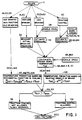
- FIG. 1 there is illustrated a simplified flow chart which illustrates the manner in which the brake lining temperature prediction of a brake control system is developed in order to enable or disable the traction control system portion of the control system.
- the vehicle's electronic control unit contains a software program beginning at BLOCK 5 and then which proceeds to determine the mode of operation of the vehicle brakes.
- the blocks of the software diagram contain numbers which correspond generally with the numbers utilized in the more detailed software flow diagram of Figures 2A and 2B and the detailed software flow diagram of Figures 3A-3C. Because the flow chart of Figure 1 is simplified, groups of BLOCK numbers apply to one or more BLOCKS and the same number may refer to more than one BLOCK. The same applies for Figures 2A and 2B relative to Figures 3A-3C.
- the software program determines whether the mode of operation for the brakes comprises a non-braking, non-traction control mode, idle or moving; a nonadaptive braking system braking application; an adaptive braking system braking application; or the utilization of the brakes during traction control. If the vehicle and brakes are below or above an idle speed, the brakes not being utilized, and the traction control system not operating as indicated in BLOCK 42, 60, 63, then the program proceeds to the cooling routine of BLOCK 47, 48/70, 105 wherein the program determines a temperature prediction based on the normal exponential function utilized in cooling. The determination of the estimated temperature prediction (T est ) then is utilized at BLOCK 52, 53 to compare T est with a preset maximum temperature (T max ). If the estimated temperature prediction is less than the preset maximum temperature, then via BLOCK 58 the operation of the traction control system is permitted and the program proceeds to the end/return BLOCK 200.
- the program evaluates the actual braking pressure utilized at the brakes (BLOCK 22) and proceeds to calculate the steady state temperature (T ss ) at BLOCK 93, 93A and B, 101.
- the steady state temperature calculation includes an input of the vehicle speed from BLOCK 85 and 85A. Once the steady state temperature (T ss ) is determined, the program utilizes that to provide an estimated temperature prediction based on the heating profile of the brake at BLOCK 105.
- the estimated temperature prediction or T est calculated at BLOCK 105 is then utilized at BLOCK 52, 53 to determine if the estimated temperature prediction is greater or less than the preset maximum temperature (T max ). If the estimated temperature prediction should exceed the preset maximum temperature, then via BLOCK 56 the traction control system is disabled and a warning light energized. The program then proceeds to the end/return BLOCK 200. If the estimated temperature prediction is less than the preset maximum temperature, the program proceeds to BLOCKS 58 and 200 as above.
- the estimated brake pressure is utilized via BLOCK 32 along with an input of vehicle deceleration from BLOCK 28 to provide an input to BLOCK 93, 93A and B, 101 in order to calculate the steady state temperature. From this point, the program proceeds as described above.
- BLOCK 60 Should the brakes be in a mode of operation during traction control as indicated at BLOCK 60, then inputs of vehicle speed (via wheel speed) and estimated pressure via BLOCKS 75, 75A, 76. 78, 80, 82 and 84 are utilized as inputs to BLOCK 93, 93A and B, 101 to calculate the steady state temperature (T ss ). The program then proceeds as described above in order to determine the estimated temperature prediction and compare it with the preset maximum temperature in order to determine whether or not the vehicle traction control system should continue to operate or be disabled.
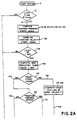
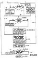
- FIGS 2A and 2B illustrate in more detail a software flow diagram which implements the method or process illustrated in Figure 1.
- the software program begins at BLOCK 5 and proceeds to BLOCK 12 where the loop time is set at 20 millisecond increments.
- the program proceeds via LINE 14 to BLOCK 16, 18, 22, 26, 28, 32, 36 where the program computes the average brake pressure every twenty milliseconds. This calculation is based on the state or mode of operation of the brakes. It may utilize transducer braking pressure if there is occurring non-ABS braking, or it may utilize calculated braking pressure if an adaptive braking system operation is occurring and the vehicle is decelerating.
- BLOCK 38 From BLOCK 16, 18, 22, 26, 28, 32, 36 the program proceeds to BLOCK 38 to compute the average velocity of a front wheel of the vehicle every 20 milliseconds.
- BLOCK 39 the time is incremented for each 20 millisecond period so that at a total count of 50 (1 second) the program will proceed to the temperature prediction calculation.
- the program proceeds to BLOCK 40 in order to compute the new predicted temperature each second. From BLOCK 40 the program considers at BLOCK 42 a front wheel speed. If the front wheel speed is greater than 13 kilometers per hour/8 miles per hour (the vehicle moving), the program proceeds via LINE 44 to BLOCK 60.
- BLOCK 47, 48 the program computes the estimated temperature prediction of the brake in a cooling mode at 0 velocity. Because of the 0 velocity, no convective cooling factor is utilized. The calculation is based on pressure, speed, and rotor characteristics. Having calculated the estimated temperature prediction at BLOCK 47, 48, the program proceeds via LINE 49 to BLOCK 50 wherein variable characteristics are reset for the next calculation before proceeding to BLOCK 52, 53, 58. At this BLOCK the estimated temperature prediction is compared with a preset maximum temperature.
- the program does not disable the traction control system and proceeds via LINE 57 to the RETURN 200. If the estimated temperature prediction is greater than the preset maximum temperature, then the traction control system is disabled via LINE 54 at BLOCK 56 and a warning signal (TOO HOT FAULT) is energized before the program proceeds via LINE 55 to the RETURN 200.
- TOO HOT FAULT a warning signal
- BLOCK 42 if it has been determined that the vehicle speed is greater than 13 kilometers per hour/8 miles per hour (vehicle and brakes moving), the program proceeds via LINE 44 to BLOCK 60 to determine whether or not the traction control system is active. Should it be determined that the traction control system is not active, the program proceeds via LINE 62 to BLOCK 63 where it is determined whether or not the brakes are applied. If it is determined that the brakes are not being applied at BLOCK 63, the program proceeds via LINE 65 to BLOCK 70 in order to set the parameters (during this loop) for cooling in the situation where the vehicle is moving. Block 70 sets the parameters for cooling which includes a convective cooling factor.
- the program proceeds from BLOCK 70 via LINE 73 to BLOCK 105 in order to compute the new temperature prediction based on rotor characteristics, heating/cooling parameters and the temperature of the last loop.
- BLOCK 105 provides an estimated temperature prediction which is transmitted via LINE 90 to BLOCK 50 and for the ultimate determination of whether or not the traction control system should continue to be enabled or should be disabled as described above. This completes a cycle of the program when it has been determined that the vehicle brakes are in a mode of operation comprising non-braking, non-traction control, vehicle moving, and with the inclusion of the convective cooling factor in the temperature prediction calculation.
- BLOCK 85, 85A the vehicle speed is analyzed to determine whether or not it exceeds 80 kilometers per hour/50 miles per hour. Should the vehicle speed be greater than 80 kilometers per hour/50 miles per hour, then at BLOCK 91 the vehicle speed is set at a maximimum of 80 kilometers per hour/50 miles per hour and the program proceeds to BLOCK 93, 93A and B, 101. Should the vehicle speed be less than 80 kilometers per hour/50 miles per hour, the program proceeds via LINE 92 directly to BLOCK 93, 93A and B, 101.
- the program sets the parameters for heating based on brake pressure (actual or estimated) and deceleration for this particular loop. After accomplishing the setting of the parameters, the program proceeds via LINE 102 to BLOCK 105 and for the accomplishment of the remainder of the program as described above.
- the software program proceeds to make a determination of the mode of operation of the brake (adaptive braking system or non-adaptive braking system operation) and then utilizes various factors (such as convective cooling, vehicle speed, braking pressure) in order to provide an estimated temperature prediction which is compared with the preset maximum temperature in order to determine whether or not the traction control system should continue to be enabled or should be disabled.
- BLOCK 60 if the traction control system is active the program proceeds via LINE 71 to BLOCK 75, 75A, 76, 78, 80, 82, 84 where estimated braking pressure is calculated as a function of vehicle speed. This estimation is inputted via LINE 64 tO BLOCK 85, 85A where the vehicle speed is analyzed to determine whether or not it exceeds 80 kilometers per hour/50 miles per hour. The program proceeds as described above wherein the steady state temperature (T ss ) is calculated and then the estimated temperature prediction is calculated and compared with the preset maximum temperature to determine if the traction control system should be disabled. This completes a cycle of the program when it has been determined initially that the vehicle brakes are in a mode of operation comprising braking during traction control system operation.
- T ss steady state temperature
- FIG. 3A-3C A more detailed description of the software program disclosed in Figures 1 and 2 and comprising a practical embodiment of such a software program is illustrated in Figures 3A-3C.
- the various BLOCKS of this detailed software program contain numbers many of which correspond to the numbers utilized in the flow diagrams of Figures 1 and 2.
- the program begins at BLOCK 5 and values are initialized such as the TEMP TIMER in BLOCK 10 wherein the clock is initially set at 0+1.
- the TEMP TIMER which operates on a 20 millisecond timer is, at BLOCK 12, divided by 4 so that a 5 millisecond time cycle is set and transmitted via LINE 14.
- BLOCK 16 establishes that for each 5 millisecond cycle the average braking pressure will be computed. It has been determined that there are three ways in which braking pressure may be utilized relative to brake lining heating or temperature. First, the pressure at a transducer either during non-adaptive braking or when the vehicle is accelerating may be related to temperature. Second, there is a linear relationship of pressure with vehicle deceleration during adaptive braking, and third, pressure may be related to vehicle speed during traction control. Returning to the diagram, BLOCK 18 is a cycling flag which indicates whether or not the adaptive braking system is operating or not operating.
- the temperature may be set for heating by utilizing the transducer pressure during non-adaptive braking system operation only when the vehicle is accelerating.
- TEMP L is equal to the boost pressure
- TEMP L plus 2 is set equal to 0 so that TEMP L equals TEMP L or the boost pressure divided by 50 which provides the boost pressure every 20 milliseconds.
- the boost pressure which is read by a boost transducer indicates how hard the boost pressure is being pushed.
- BLOCK 26 determines a relationship between pressure and heating.
- boost pressure is not representative of temperature, and therefore, BLOCK 28 directs that if the vehicle is accelerating then, via LINE 29, the temperature set for non-adaptive braking system operation is utilized because during non-adaptive braking system operation the transducer pressure is representative of braking. If the vehicle is decelerating, then via LINE 30, an equation is utilized to calculate a pressure based on a linear relationship between vehicle deceleration during adaptive braking system operation and pressure.
- BLOCK 32 involves a scaling operation necessary to scale vehicle deceleration to the boost pressure scale utilized in BLOCK 22.
- TEMP L is set equal to 2245 which is an offset necessary to place pressure in terms of deceleration.
- TEMP L+2 is then set equal to vehicle deceleration (GVEH) times 17. Then TEMP L is set equal to the offset 2245 minus the previous quantity comprising TEMP L+2.
- VWHL.LF left wheel speed
- TEMP TIMER is set to 0 for purposes of clocking of the software program. Initially, TEMP TIMER 1 is equal to TEMP TIMER 1 plus 1. BLOCK 39 then directs that TEMP TIMER be incremented by 1 so that 50 increments are equal to 1 second.
- BLOCK 40 begins the subroutines for calculating or predicting the estimated temperature of the brake linings. Proceeding from BLOCK 40 to BLOCK 42, the left front wheel of the vehicle is examined via the wheel speed sensor to determine the speed thereof. If the wheel speed is greater than approximately thirteen kilometers per hour or eight miles per hour (#1600), then the program proceeds via LINE 44. When the vehicle's speed is greater than 13 kph/8 mph, this indicates that the traction control system may be operational. If the vehicle wheel speed is equal to or less than 13 kph/8 mph, then the program proceeds via LINE 45 which goes immediately to a cooling subroutine at BLOCK 47 in Figure 3C.
- the cooling subroutine is for the non-braking, non-traction control, idle mode of brake operation and no heating of the brake linings is assumed during this mode.
- TEMP L + 2 is set at 0 and then TEMP L equals COOL 0 ⁇ VEL [R ⁇ ] which is set at an operational ambient temperature value of 100° F.
- the temperature is calculated by taking the previous TEMP LF times an exponential function, and this is derived by utilizing the formula typically utilized to predict the brake temperature of a solid brake rotor during repeated braking.
- T(t) ⁇ T i -[T x +q o /(A r h r )] ⁇ x exp ⁇ [-h r A r / ⁇ r c r v r )]t a ⁇ + T x +q o /(A r h r ),°F
- BLOCK 60 determines whether the traction control system is on or off. If the wheel speed is greater than 13 kph/8 mph and the traction control system is not operating, the program proceeds via LINE 62 to BLOCK 63 where the primary pressure is set at a nominal pressure of 84 psi by comparing PRI.PRESS with #6000. 84 psi in the braking system is approximately the minimum pressure present if the operator's foot is on the brake.
- Cooling routine 70A follows the same steps as cooling routine 40 at BLOCKS 47,48 except that "PARA" is utilized to designate this cooling routine and the ambient temperature value is 300°F for COOL PARA [R ⁇ ].
- PARA is utilized to designate this cooling routine and the ambient temperature value is 300°F for COOL PARA [R ⁇ ].
- TEMP L1 is set equal to TEMP L1 calculated plus TEMP L as an offset.
- the temperature produced is provided via LINE 90 to the scaling and resetting operations of BLOCK 50. This provides a temperature prediction which accounts for convective cooling due to the speed of the vehicle.
- the brake lining temperature prediction will be developed by relating estimated braking pressure to the vehicle speed which occurs during traction control.
- BLOCKS 75 and 75A accomplish this by first having the program look at a vehicle rear wheel speed. If at BLOCK 75A the rear wheel speed is greater than #3000 (24 kph/15 mph), then the program proceeds via LINE 76 to LINE 64 wherein the average pressure is set at BLOCK 76A as #6390 or 100 psi. This can be done because vehicle speed is related to a steady state pressure. It has been found that the lower the speed of the vehicle, the higher the pressure.
- the program proceeds to BLOCKS 78, 80 wherein if the vehicle speed is equal to or less than #1000 (8 kph/5 mph) the pressure (P.AVG) is set via LINE 81 and BLOCK 82 at #16235 (500 psi). If the vehicle speed is greater than #1000 (8 kph/5 mph), then via LINE 83 and BLOCK 84 the pressure (P.AVG) is set at #8850 (200 psi). Whichever pressure is set according to the vehicle speed, these values are transmitted by means of LINE 64 to the subroutine at BLOCKS 85, 85A.
- V.AVG the average velocity (V.AVG) is determined according to it being either less than or equal to #10000 (80 kph/50 mph). If the speed is greater than #10000 (80 kph/50 mph), V.AVG is set equal to the maximum speed of #10000 or 80 kph/50 mph at BLOCK 91 because the model requires no additional heating above this speed. If vehicle speed is less than #10000 (80 kph/50 mph), the program utilizes this speed (V.AVG) via LINE 92.
- TEMP L is equal to the average pressure (P.AVG) set by the above vehicle speed/ pressure subroutine (BLOCKS 75, 75A,76,80,82,84,85,85A) times the average velocity (V.AVG) of the vehicle.
- the calculations initialized by BLOCK 93 are resetting, in essence, the software calculations to the vehicle parameters based on pressure and speed during heating, for further use at BLOCK 105. Specifically, the numerical factors in terms of computer scaling designated by counts per mile per hour are scaled to feet per second in order to permit the utilization of TEMP L (temperature steady state) PARA [R ⁇ ] in BLOCK 105.
- TEMP L is divided by T ss (temperature steady state) PAPA [R ⁇ ] which is P.AVG times V.AVG/9.28.
- TIP L1 is set equal to V.AVG
- TEMP L1 set equal to TEMP L1 times 10 in order to scale up TEMP L1 by a factor of 10.
- TEMP L1 is then divided by T ssv PARA[R0 ⁇ ] which is a scaling factor utilized to convert computer scaling in counts/mph to ft/sec to permit the utilization of the steady state temperature (TEMP L) in BLOCK 105.
- TEMP L steady state temperature
- TEMP L steady state temperature
- BLOCK 93A if TEMP L is less than 0 it is set equal to 0 at BLOCK 93B, and if TEMP L is greater than 0 it is communicated via line 100 to BLOCK 101.
- BLOCK 101 sets TEMP L as TEMP L times the heat parameter HEAT PAPA [R0] which is an incremental change in the estimated or predicted temperature.
- HEAT PAPA [R0] is TSS times .007.
- the program proceeds via LINE 102 directly to the final calculation of TEMP L1 at BLOCK 105. Again the estimated temperature prediction equation is utilized and it is slightly different for the situation where the vehicle velocity is greater than 0.
- T o is the previously calculated temperature from the last loop multiplied by .993 (expressed as TEMP LF x EXP ⁇ PAPA [R0 ⁇ ]) and added to .007 times Temperature steady state in heating (from BLOCK 101) to provide T est which is TEMP L1.
- the program proceeds via LINE 90 to the scaling and resetting of values at BLOCK 50 and then to BLOCKS 52, 53 for the determination of whether or not the traction control system will be utilized or disabled.
Landscapes
- Engineering & Computer Science (AREA)
- Transportation (AREA)
- Mechanical Engineering (AREA)
- Physics & Mathematics (AREA)
- Fluid Mechanics (AREA)
- Chemical & Material Sciences (AREA)
- Combustion & Propulsion (AREA)
- Regulating Braking Force (AREA)
- Braking Arrangements (AREA)
- Valves And Accessory Devices For Braking Systems (AREA)
Abstract
Description
- With the proliferation of adaptive braking systems comes the opportunity to provide traction control systems as an additional system. Traction control is essentially the reverse of adaptive braking. In adaptive braking, brake pressure transmitted to the wheel brakes is sequentially released and reapplied in order to ensure that the wheels never become locked up and cause skidding of the vehicle. In traction control, the object is to keep the wheels from spinning relative to the road surface. This is accomplished by systematically applying and releasing braking pressure so that the wheels are always at approximately the maximum rotational speed of engagement with the road surface whereby the wheels maintain traction and do not begin to slip relative to the road surface. Thus, adaptive braking may be stated simply as releasing and modifying brake pressure so that the wheels do not stop spinning and lose traction relative to the road surface, while in traction control the brake pressure is applied and released so that the wheels do not spin excessively and lose traction relative to the road surface.
- One of the major concerns for traction control is the occurrence of reduced brake lining life as a result of excessive use of traction control. Specifically, if a driver has overheated the vehicle brakes, it is not desirable to utilize a prolonged traction control application. The undesirability of this results from the brake lining wear versus temperature characteristics of the brake linings. As the brake lining material becomes hotter, its wear rate, based on a fixed number of stops and pressures, increases linearly until some temperature range is reached. Beyond this temperature range, the wear rate tends to increase rapidly in an exponential manner. Through the introduction of traction control, a function has been added to the brake system which is not a mandatory safety item. As a result, it is prudent that, in order to preserve brake lining life, any non-safety related function of the brake system be disabled when the brake lining is at an extreme temperature condition and consequently in a high lining wear situation. This condition is more likely to occur if the traction control system is simply operated by pulsing brake pressure and is not interacting with or controlling engine torque output. FR-A-2 509 242 discloses a propulsion control system which utilizes a heat calculation during traction control operation, but does not provide a heat prediction during adaptive braking system operation or normal braking operation or nonbraking operation. The objective of the present invention is to implement a lining wear protection mechanism and method into traction control software, in order to temporarily disable traction control whenever the predicted lining temperature is too hot. When this condition of disabled traction control occurs, the vehicle operator may be advised by either visual and/or audible signals. The method of predicting temperature is a calculation based on the heat transfer characteristics of a particular brake. The calculation utilizes a combination of theoretical and experimental relations. The particular algorithm utilized within the method shares several of the variables utilized by adaptive braking software and thus does not require any additional hardware inputs into the electronic control unit. The temperature prediction algorithm utilized in the method keeps a real time estimate of brake lining temperature. This estimate is based upon the gross amount of energy a brake can dissipate relative to the calculated value of energy being absorbed by the brake lining.
- The present invention provides a solution to the above problems by providing in a wheeled vehicle having means for supplying pressurized brake fluid to actuate the associated wheel brakes of the vehicle, a brake control system for providing both adaptive braking operation and traction control operation of at least one selected wheel brake of the vehicle, said control system calculating a brake lining temperature prediction and including means for determining the mode of the selected wheel brake as being in traction control operation and means utilizing estimated braking pressure and vehicle wheel speed for calculating a steady state temperature and calculating a temperature prediction based on the heating profile of the brake, characterized in that the system further comprises:
- a. means for determining the mode of the selected wheel brake as being one of:
- 1. non-braking and non-traction control,
- 2. braking during non-adaptive braking operation, and
- 3. braking during adaptive braking operation,
- b. means for calculating a temperature prediction based on cooling of the selected wheel brake, when mode a.1. occurs,
- c. means for measuring actual braking pressure and calculating a steady state temperature which is utilized to calculate a temperature prediction based on a heating profile of the brake, when mode a.2. occurs,
- d. means utilizing estimated braking pressure and vehicle deceleration for calculating a steady state temperature and calculating a temperature prediction based on the heating profile of the brake, when mode a.3. occurs, and
- e. means for comparing the respective temperature prediction with a temperature limit in order to determine one of permitting and not permitting traction control operation by the control system.
- The invention is described in detail below with reference to the drawings which illustrate an embodiment in which:
- Figure 1 is a simplified flow chart of the software program contained in the invention,
- Figures 2A and 2B are a more detailed flow chart of the flow chart illustrated in Figure 1, and
- Figures 3A-3C comprise a more detailed flow chart and practical embodiment of the flow chart illustrated in Figures 2A and 2B.
- The method of brake lining temperature prediction utilizes an evaluation of the vehicle brakes in four different modes of operation. The four modes of brake operation are as listed below:
MODE TEMPERATURE STATE 1. NON-BRAKING, NON-TRACTION CONTROL, IDLE OR MOVING, COOLING 2. NORMAL BRAKING HEATING 3. ADAPTIVE BRAKING HEATING 4. TRACTION CONTROL HEATING - Referring to Figure 1, there is illustrated a simplified flow chart which illustrates the manner in which the brake lining temperature prediction of a brake control system is developed in order to enable or disable the traction control system portion of the control system. The vehicle's electronic control unit contains a software program beginning at BLOCK 5 and then which proceeds to determine the mode of operation of the vehicle brakes. The blocks of the software diagram contain numbers which correspond generally with the numbers utilized in the more detailed software flow diagram of Figures 2A and 2B and the detailed software flow diagram of Figures 3A-3C. Because the flow chart of Figure 1 is simplified, groups of BLOCK numbers apply to one or more BLOCKS and the same number may refer to more than one BLOCK. The same applies for Figures 2A and 2B relative to Figures 3A-3C. The software program determines whether the mode of operation for the brakes comprises a non-braking, non-traction control mode, idle or moving; a nonadaptive braking system braking application; an adaptive braking system braking application; or the utilization of the brakes during traction control. If the vehicle and brakes are below or above an idle speed, the brakes not being utilized, and the traction control system not operating as indicated in
BLOCK BLOCK return BLOCK 200. - Should it be determined that the vehicle brakes are in the mode of operation occurring during nonadaptive braking system braking (normal braking) as shown at
BLOCK BLOCK 105 is then utilized atBLOCK return BLOCK 200. If the estimated temperature prediction is less than the preset maximum temperature, the program proceeds to BLOCKS 58 and 200 as above. - Referring to BLOCK 18, 26, 63 of the flow diagram of Figure 1, should the brakes be in a mode of operation during adaptive braking system braking, the estimated brake pressure is utilized via
BLOCK 32 along with an input of vehicle deceleration fromBLOCK 28 to provide an input to BLOCK 93, 93A and B, 101 in order to calculate the steady state temperature. From this point, the program proceeds as described above. - Should the brakes be in a mode of operation during traction control as indicated at
BLOCK 60, then inputs of vehicle speed (via wheel speed) and estimated pressure viaBLOCKS - Figures 2A and 2B illustrate in more detail a software flow diagram which implements the method or process illustrated in Figure 1. The software program begins at
BLOCK 5 and proceeds to BLOCK 12 where the loop time is set at 20 millisecond increments. The program proceeds viaLINE 14 to BLOCK 16, 18, 22, 26, 28, 32, 36 where the program computes the average brake pressure every twenty milliseconds. This calculation is based on the state or mode of operation of the brakes. It may utilize transducer braking pressure if there is occurring non-ABS braking, or it may utilize calculated braking pressure if an adaptive braking system operation is occurring and the vehicle is decelerating. FromBLOCK BLOCK 39 the time is incremented for each 20 millisecond period so that at a total count of 50 (1 second) the program will proceed to the temperature prediction calculation. At one second, the program proceeds to BLOCK 40 in order to compute the new predicted temperature each second. FromBLOCK 40 the program considers at BLOCK 42 a front wheel speed. If the front wheel speed is greater than 13 kilometers per hour/8 miles per hour (the vehicle moving), the program proceeds viaLINE 44 to BLOCK 60. If the front wheel speed is less than or equal to 13 kilometers per hour/8 miles per hour (the vehicle and brakes at idle), the program proceeds viaLINE 45 to BLOCK 47, 48. AtBLOCK BLOCK LINE 49 to BLOCK 50 wherein variable characteristics are reset for the next calculation before proceeding to BLOCK 52, 53, 58. At this BLOCK the estimated temperature prediction is compared with a preset maximum temperature. If the estimated temperature prediction is less than the preset maximum temperature, then the program does not disable the traction control system and proceeds viaLINE 57 to theRETURN 200. If the estimated temperature prediction is greater than the preset maximum temperature, then the traction control system is disabled viaLINE 54 atBLOCK 56 and a warning signal (TOO HOT FAULT) is energized before the program proceeds viaLINE 55 to theRETURN 200. This completes a typical cycle of the program when it has been determined that the vehicle brakes are in a mode of operation comprising non-braking, non-traction control, and the vehicle at idle speed comprising less than or equal to 13 kph/8 mph. - Returning to BLOCK 42, if it has been determined that the vehicle speed is greater than 13 kilometers per hour/8 miles per hour (vehicle and brakes moving), the program proceeds via
LINE 44 to BLOCK 60 to determine whether or not the traction control system is active. Should it be determined that the traction control system is not active, the program proceeds viaLINE 62 to BLOCK 63 where it is determined whether or not the brakes are applied. If it is determined that the brakes are not being applied atBLOCK 63, the program proceeds viaLINE 65 to BLOCK 70 in order to set the parameters (during this loop) for cooling in the situation where the vehicle is moving.Block 70 sets the parameters for cooling which includes a convective cooling factor. The program proceeds fromBLOCK 70 viaLINE 73 to BLOCK 105 in order to compute the new temperature prediction based on rotor characteristics, heating/cooling parameters and the temperature of the last loop.BLOCK 105 provides an estimated temperature prediction which is transmitted viaLINE 90 to BLOCK 50 and for the ultimate determination of whether or not the traction control system should continue to be enabled or should be disabled as described above. This completes a cycle of the program when it has been determined that the vehicle brakes are in a mode of operation comprising non-braking, non-traction control, vehicle moving, and with the inclusion of the convective cooling factor in the temperature prediction calculation. - Returning to BLOCK 63, should it be determined that the brakes are applied but in a situation where the traction control system is not active, the program proceeds via
LINE 64 to BLOCK 85, 85A where the vehicle speed is analyzed to determine whether or not it exceeds 80 kilometers per hour/50 miles per hour. Should the vehicle speed be greater than 80 kilometers per hour/50 miles per hour, then atBLOCK 91 the vehicle speed is set at a maximimum of 80 kilometers per hour/50 miles per hour and the program proceeds to BLOCK 93, 93A and B, 101. Should the vehicle speed be less than 80 kilometers per hour/50 miles per hour, the program proceeds viaLINE 92 directly toBLOCK BLOCK LINE 102 to BLOCK 105 and for the accomplishment of the remainder of the program as described above. Thus, the software program proceeds to make a determination of the mode of operation of the brake (adaptive braking system or non-adaptive braking system operation) and then utilizes various factors (such as convective cooling, vehicle speed, braking pressure) in order to provide an estimated temperature prediction which is compared with the preset maximum temperature in order to determine whether or not the traction control system should continue to be enabled or should be disabled. - Returning to BLOCK 60, if the traction control system is active the program proceeds via
LINE 71 to BLOCK 75, 75A, 76, 78, 80, 82, 84 where estimated braking pressure is calculated as a function of vehicle speed. This estimation is inputted viaLINE 64 tOBLOCK - A more detailed description of the software program disclosed in Figures 1 and 2 and comprising a practical embodiment of such a software program is illustrated in Figures 3A-3C. The various BLOCKS of this detailed software program contain numbers many of which correspond to the numbers utilized in the flow diagrams of Figures 1 and 2. Referring to the BLOCK diagrams of the software program in Figures 3A-3C utilized for brake lining temperature prediction, the program begins at
BLOCK 5 and values are initialized such as the TEMP TIMER inBLOCK 10 wherein the clock is initially set at 0+1. The TEMP TIMER which operates on a 20 millisecond timer is, atBLOCK 12, divided by 4 so that a 5 millisecond time cycle is set and transmitted viaLINE 14.BLOCK 16 establishes that for each 5 millisecond cycle the average braking pressure will be computed. It has been determined that there are three ways in which braking pressure may be utilized relative to brake lining heating or temperature. First, the pressure at a transducer either during non-adaptive braking or when the vehicle is accelerating may be related to temperature. Second, there is a linear relationship of pressure with vehicle deceleration during adaptive braking, and third, pressure may be related to vehicle speed during traction control. Returning to the diagram,BLOCK 18 is a cycling flag which indicates whether or not the adaptive braking system is operating or not operating. If the adaptive braking system is not operating, then viaLINE 20 the temperature may be set for heating by utilizing the transducer pressure during non-adaptive braking system operation only when the vehicle is accelerating. In accordance withBLOCK 22 indicating that the TEMP 0̸0̸ is to be determined, TEMP L is equal to the boost pressure, and then TEMP L plus 2 is set equal to 0 so that TEMP L equals TEMP L or the boost pressure divided by 50 which provides the boost pressure every 20 milliseconds. The boost pressure which is read by a boost transducer indicates how hard the boost pressure is being pushed. - If the adaptive braking system is operating, then via
LINE 24 the TEMP R at 0̸ subroutine is utilized viaBLOCK 26 to determine a relationship between pressure and heating. During adaptive braking system operation, boost pressure is not representative of temperature, and therefore,BLOCK 28 directs that if the vehicle is accelerating then, viaLINE 29, the temperature set for non-adaptive braking system operation is utilized because during non-adaptive braking system operation the transducer pressure is representative of braking. If the vehicle is decelerating, then viaLINE 30, an equation is utilized to calculate a pressure based on a linear relationship between vehicle deceleration during adaptive braking system operation and pressure. Because pressure relative to vehicle deceleration during adaptive braking system cycling is not precisely known, it is necessary to estimate the pressure relative to deceleration. The equations atBLOCK 32 are executed to provide approximate pressure during deceleration.BLOCK 32 involves a scaling operation necessary to scale vehicle deceleration to the boost pressure scale utilized inBLOCK 22. First, TEMP L is set equal to 2245 which is an offset necessary to place pressure in terms of deceleration. TEMP L+2 is then set equal to vehicle deceleration (GVEH) times 17. Then TEMP L is set equal to the offset 2245 minus the previous quantity comprising TEMP L+2. This completes the scaling of the pressure/temperature relationship during vehicle deceleration so that it may be utilized viaLINE 34 atBLOCK 36 just as the TEMP L factor provided byBLOCK 22 viaLINE 33 may be utilized atBLOCK 36. In whichever manner the relationship occurs between pressure and temperature in relation to the adaptive braking system, the program proceeds via eitherLINES BLOCK 36, the average pressure is set by taking the TEMP L value (BLOCKS 22 and 32) relating to pressure and adding it to P AVERAGE (average pressure) each 20 milliseconds. Next, according toBLOCK 38, the average velocity (V.AVG) of the vehicle is computed by setting TEMP L+2=0 and then looking at the left wheel speed (VWHL.LF) of the vehicle and dividing this by 50 so that the average velocity (V.AVG) is equal to the initial average velocity (V.AVG) plus the TEMP L calculated previously. This now creates the pressure and velocity relationship. Next TEMP TIMER is set to 0 for purposes of clocking of the software program. Initially,TEMP TIMER 1 is equal toTEMP TIMER 1plus 1.BLOCK 39 then directs that TEMP TIMER be incremented by 1 so that 50 increments are equal to 1 second. AtBLOCK 40 begins the subroutines for calculating or predicting the estimated temperature of the brake linings. Proceeding fromBLOCK 40 to BLOCK 42, the left front wheel of the vehicle is examined via the wheel speed sensor to determine the speed thereof. If the wheel speed is greater than approximately thirteen kilometers per hour or eight miles per hour (#1600), then the program proceeds viaLINE 44. When the vehicle's speed is greater than 13 kph/8 mph, this indicates that the traction control system may be operational. If the vehicle wheel speed is equal to or less than 13 kph/8 mph, then the program proceeds viaLINE 45 which goes immediately to a cooling subroutine atBLOCK 47 in Figure 3C. The cooling subroutine is for the non-braking, non-traction control, idle mode of brake operation and no heating of the brake linings is assumed during this mode. Referring to the cooling subroutine beginning withBLOCK 47, TEMP L + 2 is set at 0 and then TEMP L equals COOL 0̸VEL [RØ] which is set at an operational ambient temperature value of 100° F. In order to calculate and predict the temperature in accordance withBLOCK 48, the temperature is calculated by taking the previous TEMP LF times an exponential function, and this is derived by utilizing the formula typically utilized to predict the brake temperature of a solid brake rotor during repeated braking. The formula is a well known formula which is described in SAE Seminars entitled: "Brakes: Design and Safety, Chapter 3, Thermal Analysis of Friction Brakes". SAE Seminars present a number of rotor temperature prediction mechanisms, this particular mechanism being for the prediction of brake temperature during repeated braking. If the braking time is considered not negligible as compared to the cooling time, then the cooling during braking has to be included in the analysis. The formulation results in the temperature response:

where - Ar =
- rotor surface area, ft²
- hr =
- heat transfer coefficient, BTU/h·°F·ft²
- T =
- temperature at time t, °F
- Tx =
- ambient temperature, °F
- Ti =
- initial temperature, °F
- cr =
- specific heat of rotor, BTU/lbm·°F
- vr =
- rotor volume, ft³
- ρr =
- rotor density, lbm/ft³
- qo =
- braking energy absorbed by rotor, BTU/h
- ta =
- time during which brakes are applied, h
- Returning to BLOCK 42 in Figure 3A, if the vehicle wheel speed is greater than 13 kph/8 mph, then the program proceeds via
LINE 44 to BLOCK 60 which determines whether the traction control system is on or off. If the wheel speed is greater than 13 kph/8 mph and the traction control system is not operating, the program proceeds viaLINE 62 to BLOCK 63 where the primary pressure is set at a nominal pressure of 84 psi by comparing PRI.PRESS with #6000. 84 psi in the braking system is approximately the minimum pressure present if the operator's foot is on the brake. If the pressure is 84 psi or greater, then (via LINE 64) this indicates that during non-traction control system operation the vehicle operator may be braking and thus effecting heating of the brake linings, and the program proceeds toBLOCKS LINE 65 upon the assumption that the vehicle operator is not braking the vehicle.LINE 65 proceeds directly to thesecond cooling routine 70A (Figure 3C) atBLOCK 70 andBLOCK 105 which is essentially the same as thecooling routine 40 atBLOCKS BLOCKS BLOCK 105 by setting it equal to the previous temperature (TEMP LF) times the exponential EXP PAPA [RØ], EXP PAPA [RØ] equals 0.993. TEMP L1 is set equal to TEMP L1 calculated plus TEMP L as an offset. The temperature produced is provided viaLINE 90 to the scaling and resetting operations ofBLOCK 50. This provides a temperature prediction which accounts for convective cooling due to the speed of the vehicle. A further explanation of the equation utilized inBLOCK 105 is contained below with reference to Figure 1. - Returning to BLOCK 60 and proceeding via
LINE 71 if there is an indication that the traction control system is operating, the brake lining temperature prediction will be developed by relating estimated braking pressure to the vehicle speed which occurs during traction control. BLOCKS 75 and 75A accomplish this by first having the program look at a vehicle rear wheel speed. If atBLOCK 75A the rear wheel speed is greater than #3000 (24 kph/15 mph), then the program proceeds viaLINE 76 to LINE 64 wherein the average pressure is set atBLOCK 76A as #6390 or 100 psi. This can be done because vehicle speed is related to a steady state pressure. It has been found that the lower the speed of the vehicle, the higher the pressure. Thus, viaLINE 77 if the vehicle speed is equal to or less than #3000 (24 kph/15 mph),the program proceeds toBLOCKS LINE 81 andBLOCK 82 at #16235 (500 psi). If the vehicle speed is greater than #1000 (8 kph/5 mph), then viaLINE 83 andBLOCK 84 the pressure (P.AVG) is set at #8850 (200 psi). Whichever pressure is set according to the vehicle speed, these values are transmitted by means ofLINE 64 to the subroutine at BLOCKS 85, 85A. AtBLOCK 85A, the average velocity (V.AVG) is determined according to it being either less than or equal to #10000 (80 kph/50 mph). If the speed is greater than #10000 (80 kph/50 mph), V.AVG is set equal to the maximum speed of #10000 or 80 kph/50 mph atBLOCK 91 because the model requires no additional heating above this speed. If vehicle speed is less than #10000 (80 kph/50 mph), the program utilizes this speed (V.AVG) viaLINE 92. Proceeding with the TIP L (Tss or Temperature Steady State) prediction calculation atBLOCK 93, TEMP L is equal to the average pressure (P.AVG) set by the above vehicle speed/ pressure subroutine (BLOCKS 75, 75A,76,80,82,84,85,85A) times the average velocity (V.AVG) of the vehicle. The calculations initialized byBLOCK 93 are resetting, in essence, the software calculations to the vehicle parameters based on pressure and speed during heating, for further use atBLOCK 105. Specifically, the numerical factors in terms of computer scaling designated by counts per mile per hour are scaled to feet per second in order to permit the utilization of TEMP L (temperature steady state) PARA [RØ] inBLOCK 105. TEMP L is divided by Tss (temperature steady state) PAPA [RØ] which is P.AVG times V.AVG/9.28. TIP L1 is set equal to V.AVG, and TEMP L1 set equal toTEMP L1 times 10 in order to scale up TEMP L1 by a factor of 10. TEMP L1 is then divided by Tssv PARA[R0̸] which is a scaling factor utilized to convert computer scaling in counts/mph to ft/sec to permit the utilization of the steady state temperature (TEMP L) inBLOCK 105. Finally, TEMP L (steady state temperature) is set equal to TEMP L - TEMP L1. AtBLOCK 93A, if TEMP L is less than 0 it is set equal to 0 atBLOCK 93B, and if TEMP L is greater than 0 it is communicated vialine 100 to BLOCK 101.BLOCK 101 sets TEMP L as TEMP L times the heat parameter HEAT PAPA [R0] which is an incremental change in the estimated or predicted temperature. Thus, TEMP L times HEAT PARA [R0] is TSS times .007. The program proceeds viaLINE 102 directly to the final calculation of TEMP L1 atBLOCK 105. Again the estimated temperature prediction equation is utilized and it is slightly different for the situation where the vehicle velocity is greater than 0. Referring to Figure 1,BLOCK 105 estimates the tempera- ture by utilizing the basic equation


LINE 90 to the scaling and resetting of values atBLOCK 50 and then to BLOCKS 52, 53 for the determination of whether or not the traction control system will be utilized or disabled.
Claims (10)
- A brake control system, in a wheeled vehicle having means for supplying pressurized brake fluid to actuate the associated wheel brakes of the vehicle, for providing both adaptive braking operation and traction control operation of at least one selected wheel brake of the vehicle, said control system calculating a brake lining temperature prediction (47, 48/70, 105) and including means for determining the mode (60) of the selected wheel brake as being in traction control operation and means utilizing estimated braking pressure (80, 82, 84) and vehicle wheel speed (75, 75A, 76, 78) for calculating a steady state temperature (93, 93A & B, 101) and calculating a temperature prediction (105) based on the heating profile of the brake, characterized in that control system further comprises:a. means for determining the mode (42, 60, 63; 18, 63; 18, 26, 63) of the selected wheel brake as being one of:1. non-braking and non-traction control (42, 60, 63),2. braking during non-adaptive braking operation (18, 63), and3. braking during adaptive braking operation (18, 26, 63),b. means for calculating a temperature prediction based on cooling (47, 48/70, 105) of the selected wheel brake, when mode a.1. occurs,c. means for measuring actual braking pressure (22) and calculating a steady state temperature (93, 93A & B, 101) which is utilized to calculate a temperature prediction (105) based on a heating profile of the brake, when mode a.2. occurs,d. means utilizing estimated braking pressure (32) and vehicle deceleration (28) for calculating a steady state temperature (93, 93A & B, 101) and calculating a temperature prediction (105) based on the heating profile of the brake, when mode a.3. occurs, ande. means for comparing the respective temperature prediction with a temperature limit (52, 53) in order to determine one of permitting (58) and not permitting (56) traction control operation by the control system.
- The brake control system in accordance with Claim 1, characterized in that the means for calculating a temperature prediction based on cooling of the selected wheel brake (47, 48/70, 105) utilizes a convective cooling factor (70) when vehicle speed exceeds approximately thirteen kilometers per hour.
- The brake control system in accordance with Claim 1, characterized in that the means of paragraphs c. and d. utilize an input of vehicle speed (85, 85A).
- The brake control system in accordance with Claim 1, characterized in that the system further comprises means for providing a warning signal (56) should traction control operation not be permitted.
- The brake control system in accordance with Claim 4, characterized in that the warning signal means (56) includes means for retaining (56) an indication that the temperature prediction exceeded the temperature limit.
- A method of calculating a brake lining temperature prediction for the control of a braking system including an adaptive braking and traction control system, the method including determining the mode (60) of a brake as being in traction control system operation and utilizing estimated braking pressure (80, 92, 84) and vehicle wheel speed (75, 75A, 76, 78) for the calculation of a steady state temperature (93, 93A & B, 101) utilized to calculate a temperature prediction (105) based on the heating profile of the brake, and comparing the temperature prediction (105) with a temperature limit (52, 53) to control traction control operation of the control system, characterized in that the steps further comprise:a. determining the mode (42, 60, 63; 18, 63; 18, 25, 63) of a brake as being one of:1. non-braking and non-traction control (42, 60, 63)2. braking during non-adaptive braking system operation (18, 63), and3. braking during adaptive braking system operation (18, 26, 63),b. calculating a temperature prediction based on cooling (47, 48/70, 105) of the brake, when mode a.1. occurs,c. measuring actual braking pressure (22) and calculating a steady state temperature (93, 93A & B, 101) which is then utilized to calculate a temperature prediction (105) based on a heating profile of the brake, when mode a.2. occurs,d. utilizing an estimation of braking pressure (32) and vehicle deceleration (28) for the calculation of a steady state temperature (93, 93A & B, 101) and calculating a temperature prediction (105) based on a heating profile of a brake, when mode a.3. occurs, ande. comparing the temperature prediction with a temperature limit (52, 53) in order to effect one of permitting (58) and not permitting (56) operation of the traction control system.
- The method of brake lining temperature prediction and control in accordance with Claim 6, characterized in that step b. includes the step of determining if a vehicle wheel is moving at one of above and below a slow moving speed (42) of approximately thirteen kilometers per hour.
- The method of brake lining temperature prediction and control in accordance with Claim 6, characterized in that the steps of calculating a steady state temperature (93, 93A & B, 101) in paragraphs c. and d. further include the step of utilizing an input (85, 85A) of vehicle speed.
- The method of brake lining temperature prediction and control in accordance with Claim 8, characterized in that the method includes the step of providing a warning signal (56) should operation of the traction control system not be permitted.
- The method of brake lining temperature prediction and control in accordance with Claim 6, characterized in that the method further comprises the step of retaining an indication (56) that the temperature prediction exceeded the temperature limit should the traction control system not be permitted to operate.
Applications Claiming Priority (3)
| Application Number | Priority Date | Filing Date | Title |
|---|---|---|---|
| US540679 | 1990-06-19 | ||
| US07/540,679 US5136508A (en) | 1990-06-19 | 1990-06-19 | Brake lining temperature prediction for a traction control system |
| PCT/US1991/003220 WO1991019632A1 (en) | 1990-06-19 | 1991-05-09 | Brake lining temperature prediction for a traction control system |
Publications (2)
| Publication Number | Publication Date |
|---|---|
| EP0534998A1 EP0534998A1 (en) | 1993-04-07 |
| EP0534998B1 true EP0534998B1 (en) | 1994-11-30 |
Family
ID=24156484
Family Applications (1)
| Application Number | Title | Priority Date | Filing Date |
|---|---|---|---|
| EP91909584A Expired - Lifetime EP0534998B1 (en) | 1990-06-19 | 1991-05-09 | Brake lining temperature prediction for a traction control system |
Country Status (7)
| Country | Link |
|---|---|
| US (1) | US5136508A (en) |
| EP (1) | EP0534998B1 (en) |
| JP (1) | JPH0794218B2 (en) |
| AU (1) | AU637707B2 (en) |
| CA (1) | CA2082151A1 (en) |
| DE (1) | DE69105506T2 (en) |
| WO (1) | WO1991019632A1 (en) |
Families Citing this family (30)
| Publication number | Priority date | Publication date | Assignee | Title |
|---|---|---|---|---|
| DE4418768C2 (en) * | 1994-05-28 | 1996-12-12 | Daimler Benz Ag | Method for determining the braking surface temperature for a motor vehicle wheel |
| US5731975A (en) * | 1994-08-05 | 1998-03-24 | Toyota Jidosha Kabushiki Kaisha | Temperature assuming apparatus for a brake pad and wheel slip controlling apparatus using the same |
| US5596513A (en) * | 1995-01-05 | 1997-01-21 | Caterpillar Inc. | Method and apparatus for estimating internal brake energy |
| FR2733830B1 (en) * | 1995-05-05 | 1997-06-06 | Gec Alsthom Transport Sa | DEVICE AND METHOD FOR EVALUATING THE INSTANTANEOUS TEMPERATURE AND / OR CONTROLLING THE HEATING AND / OR EXTRAPOLATING THE BALANCE TEMPERATURE OF MOBILE MEANS |
| US5613744A (en) * | 1995-05-24 | 1997-03-25 | Allied Signal, Inc. | Incipient brake fade detection for traction control systems |
| US5685619A (en) * | 1996-02-21 | 1997-11-11 | Catepillar Inc. | Energy management method for a traction control system |
| DE19706850B4 (en) * | 1997-02-21 | 2007-12-13 | Robert Bosch Gmbh | Method and device for controlling a brake system of a vehicle |
| US6119059A (en) * | 1998-03-26 | 2000-09-12 | Institute Of Occupational Safety And Health, Council Of Labor Affairs, Executive Yuan | Advanced warning device for monitoring the working conditions of hydraulic brakes system of motor vehicles |
| FR2800821B1 (en) * | 1999-11-10 | 2002-01-11 | Peugeot Citroen Automobiles Sa | HYDRAULIC BRAKING DEVICE WITH CIRCULATED COOLED FLUID |
| ES2169667B1 (en) * | 2000-05-09 | 2003-12-16 | Marin Jose Oliva | DEVICE FOR THE PREVENTION OF LACK OF BRAKING CAPACITY. |
| US6356832B1 (en) | 2000-11-28 | 2002-03-12 | Ford Global Technologies, Inc. | Anti-lock brake control system having enhanced straightline braking efficiency |
| US6456922B1 (en) | 2000-11-28 | 2002-09-24 | Ford Global Technologies, Inc. | Anti-lock brake control system to reduce thermal load |
| DE10164717C2 (en) * | 2001-02-12 | 2003-05-15 | Knorr Bremse Systeme | Method for reducing the operating temperature of electromechanical brake application devices of a vehicle brake |
| JP2004529027A (en) * | 2001-03-28 | 2004-09-24 | コンティネンタル・テーベス・アクチエンゲゼルシヤフト・ウント・コンパニー・オッフェネ・ハンデルスゲゼルシヤフト | How to improve control response and heat load tolerance of automotive control systems |
| US20030110849A1 (en) * | 2001-06-29 | 2003-06-19 | Lonzinski Richard J. | Method and apparatus for limiting truck speed as a function of braking |
| DE10150276B4 (en) | 2001-10-12 | 2008-12-11 | Daimler Ag | Method for determining the temperature of a wheel brake device of a brake system |
| US6612736B2 (en) | 2001-10-26 | 2003-09-02 | Delphi Technologies, Inc. | Method and apparatus for estimating vehicle brake rotor temperature |
| DE10254819A1 (en) * | 2002-11-25 | 2004-06-09 | Robert Bosch Gmbh | Limit load-dependent partial shutdown of individual functions of the system components of a vehicle |
| KR101142361B1 (en) | 2006-08-07 | 2012-05-18 | 주식회사 만도 | Control method for traction control system |
| KR101314773B1 (en) * | 2008-10-10 | 2013-10-14 | 주식회사 만도 | Method of estimating temperature for vehicle brake disk |
| JP5842877B2 (en) * | 2013-07-23 | 2016-01-13 | 株式会社アドヴィックス | Brake temperature detection device and electric parking brake control device |
| US9914442B2 (en) * | 2013-08-21 | 2018-03-13 | The Boeing Company | Stopping energy based selection logic for taxi brake release |
| US9180855B2 (en) * | 2014-02-11 | 2015-11-10 | Goodrich Corporation | Brake cooling estimation methods and systems |
| US10300898B2 (en) | 2017-01-23 | 2019-05-28 | Deere & Company | Cart and implement combination having a brake system |
| CN107120370B (en) * | 2017-04-27 | 2019-01-08 | 广州汽车集团股份有限公司 | The guard method of clutch and device in vehicle travel process |
| US11383689B2 (en) | 2018-05-23 | 2022-07-12 | Haldex Brake Products Corporation | Brake monitoring system with temperature monitoring |
| CN112431876B (en) * | 2019-08-26 | 2022-05-27 | 上海汽车集团股份有限公司 | Method and device for temperature estimation of dry clutch |
| CN111853100B (en) * | 2020-07-31 | 2022-03-08 | 日立电梯(广州)自动扶梯有限公司 | Escalator brake system and control method |
| EP3964408B1 (en) * | 2020-09-04 | 2023-06-28 | KNORR-BREMSE Systeme für Nutzfahrzeuge GmbH | Method and equipment for estimating a braking factor for a braking system for a vehicle |
| US12227157B2 (en) * | 2021-10-01 | 2025-02-18 | Ford Global Technologies, Llc | Methods and apparatus to extend brake life cycle |
Family Cites Families (7)
| Publication number | Priority date | Publication date | Assignee | Title |
|---|---|---|---|---|
| US4241603A (en) * | 1979-02-02 | 1980-12-30 | The Bendix Corporation | Aircraft brake thermal sensor |
| DE3127302C2 (en) * | 1981-07-10 | 1983-09-15 | Daimler-Benz Ag, 7000 Stuttgart | "Device for propulsion control on motor vehicles" |
| US4591213A (en) * | 1983-04-21 | 1986-05-27 | Landaire Dynabrake, Inc. | Braking system |
| FR2577480B1 (en) * | 1985-02-21 | 1987-12-11 | Labinal | DEVICE FOR MEASURING BRAKE TEMPERATURES AND TIRE PRESSURES ON VEHICLE WHEEL TRAINS AND ESPECIALLY AIRCRAFT |
| DE3540708A1 (en) * | 1985-11-16 | 1987-05-21 | Bosch Gmbh Robert | DRIVE CONTROL SYSTEM |
| DE8702948U1 (en) * | 1987-02-07 | 1987-05-14 | Haagen & Rinau Mischtechnik Gmbh, 2800 Bremen | Mixing device |
| DE3805589A1 (en) * | 1988-02-23 | 1989-08-31 | Lucas Ind Plc | METHOD AND DEVICE FOR CONTROLLING A BRAKE SYSTEM FOR HEAVY VEHICLES |
-
1990
- 1990-06-19 US US07/540,679 patent/US5136508A/en not_active Expired - Fee Related
-
1991
- 1991-05-09 AU AU78738/91A patent/AU637707B2/en not_active Ceased
- 1991-05-09 CA CA002082151A patent/CA2082151A1/en not_active Abandoned
- 1991-05-09 EP EP91909584A patent/EP0534998B1/en not_active Expired - Lifetime
- 1991-05-09 DE DE69105506T patent/DE69105506T2/en not_active Expired - Fee Related
- 1991-05-09 WO PCT/US1991/003220 patent/WO1991019632A1/en not_active Ceased
- 1991-05-09 JP JP3509421A patent/JPH0794218B2/en not_active Expired - Lifetime
Also Published As
| Publication number | Publication date |
|---|---|
| US5136508A (en) | 1992-08-04 |
| CA2082151A1 (en) | 1991-12-20 |
| WO1991019632A1 (en) | 1991-12-26 |
| JPH05506828A (en) | 1993-10-07 |
| JPH0794218B2 (en) | 1995-10-11 |
| EP0534998A1 (en) | 1993-04-07 |
| DE69105506D1 (en) | 1995-01-12 |
| AU7873891A (en) | 1992-01-07 |
| DE69105506T2 (en) | 1995-04-13 |
| AU637707B2 (en) | 1993-06-03 |
Similar Documents
| Publication | Publication Date | Title |
|---|---|---|
| US5136508A (en) | Brake lining temperature prediction for a traction control system | |
| CA2109891C (en) | Method and apparatus for estimating vehicle braking system effectiveness | |
| US7011186B2 (en) | Method for determining a brake state | |
| JP2593424B2 (en) | How to determine the braking surface temperature of a vehicle wheel | |
| US4964679A (en) | Monitoring method and apparatus for a brake system of heavy-duty vehicles | |
| US11047439B2 (en) | Intelligent brake system health monitoring | |
| EP1000270B1 (en) | Method and apparatus for detecting an improperly adjusted slack adjuster for brakes | |
| US7320506B2 (en) | Method for reconditioning a friction couple in a service brake and a vehicle including a friction couple arranged in said vehicle | |
| US11867246B2 (en) | Wear volume estimation device, wear volume estimation method, and wear volume estimation program | |
| US5184875A (en) | Method for operating the brake system of a commercial vehicle | |
| CN101356087A (en) | System for controlling main brake of a vehicle | |
| US5390120A (en) | Method and apparatus for determining a need for vehicle braking system maintenance | |
| EP0247253A1 (en) | Braking system | |
| US6460941B1 (en) | Method for controlling brake-pressure characteristics in the rear wheel brakes of a motor vehicle brake system with electronic regulation of brake power distribution | |
| US5669679A (en) | Brake system control | |
| JP3585707B2 (en) | Method of estimating temperature of brake friction material in vehicle | |
| US5620240A (en) | Anti-lock brake method and system including a variable primary to secondary apply hold stage | |
| EP0435227B1 (en) | Anti-lock control method for automotive vehicles | |
| JP2501559B2 (en) | Driving force control device for self-propelled vehicle | |
| CN117774982A (en) | Electric vehicle auxiliary braking control method, system and electric vehicle | |
| WO2002032735A1 (en) | Method and apparatus to control the braking of a hydraulic auxiliary brake in a vehicle | |
| EP0567861A1 (en) | Method and system for controlling brake pressure under "low Mu braking surface" (surface with a low coefficient of friction) conditions in a vehicular ABS | |
| WO1999000280A1 (en) | Algorithm for scheduling extra reapply pulses in a rear wheel anti-lock brake system | |
| WO2008140400A1 (en) | Brake control arrangement and method for braking a motor vehicle | |
| JPS60185663A (en) | Interrupting method of antiskid control |
Legal Events
| Date | Code | Title | Description |
|---|---|---|---|
| PUAI | Public reference made under article 153(3) epc to a published international application that has entered the european phase |
Free format text: ORIGINAL CODE: 0009012 |
|
| 17P | Request for examination filed |
Effective date: 19921119 |
|
| AK | Designated contracting states |
Kind code of ref document: A1 Designated state(s): DE FR GB IT SE |
|
| 17Q | First examination report despatched |
Effective date: 19940209 |
|
| GRAA | (expected) grant |
Free format text: ORIGINAL CODE: 0009210 |
|
| RAP1 | Party data changed (applicant data changed or rights of an application transferred) |
Owner name: ALLIEDSIGNAL INC. |
|
| AK | Designated contracting states |
Kind code of ref document: B1 Designated state(s): DE FR GB IT SE |
|
| PG25 | Lapsed in a contracting state [announced via postgrant information from national office to epo] |
Ref country code: IT Free format text: LAPSE BECAUSE OF FAILURE TO SUBMIT A TRANSLATION OF THE DESCRIPTION OR TO PAY THE FEE WITHIN THE PRESCRIBED TIME-LIMIT;WARNING: LAPSES OF ITALIAN PATENTS WITH EFFECTIVE DATE BEFORE 2007 MAY HAVE OCCURRED AT ANY TIME BEFORE 2007. THE CORRECT EFFECTIVE DATE MAY BE DIFFERENT FROM THE ONE RECORDED. Effective date: 19941130 |
|
| REF | Corresponds to: |
Ref document number: 69105506 Country of ref document: DE Date of ref document: 19950112 |
|
| ET | Fr: translation filed | ||
| PLBE | No opposition filed within time limit |
Free format text: ORIGINAL CODE: 0009261 |
|
| STAA | Information on the status of an ep patent application or granted ep patent |
Free format text: STATUS: NO OPPOSITION FILED WITHIN TIME LIMIT |
|
| 26N | No opposition filed | ||
| PGFP | Annual fee paid to national office [announced via postgrant information from national office to epo] |
Ref country code: SE Payment date: 19960418 Year of fee payment: 6 |
|
| PG25 | Lapsed in a contracting state [announced via postgrant information from national office to epo] |
Ref country code: SE Effective date: 19970510 |
|
| REG | Reference to a national code |
Ref country code: FR Ref legal event code: TP |
|
| REG | Reference to a national code |
Ref country code: GB Ref legal event code: 732E |
|
| EUG | Se: european patent has lapsed |
Ref document number: 91909584.4 |
|
| PGFP | Annual fee paid to national office [announced via postgrant information from national office to epo] |
Ref country code: GB Payment date: 19990426 Year of fee payment: 9 |
|
| PGFP | Annual fee paid to national office [announced via postgrant information from national office to epo] |
Ref country code: FR Payment date: 19990520 Year of fee payment: 9 |
|
| PGFP | Annual fee paid to national office [announced via postgrant information from national office to epo] |
Ref country code: DE Payment date: 19990719 Year of fee payment: 9 |
|
| PG25 | Lapsed in a contracting state [announced via postgrant information from national office to epo] |
Ref country code: GB Free format text: LAPSE BECAUSE OF NON-PAYMENT OF DUE FEES Effective date: 20000509 |
|
| GBPC | Gb: european patent ceased through non-payment of renewal fee |
Effective date: 20000509 |
|
| PG25 | Lapsed in a contracting state [announced via postgrant information from national office to epo] |
Ref country code: FR Free format text: LAPSE BECAUSE OF NON-PAYMENT OF DUE FEES Effective date: 20010131 |
|
| PG25 | Lapsed in a contracting state [announced via postgrant information from national office to epo] |
Ref country code: DE Free format text: LAPSE BECAUSE OF NON-PAYMENT OF DUE FEES Effective date: 20010301 |
|
| REG | Reference to a national code |
Ref country code: FR Ref legal event code: ST |