EP0534579B1 - Plate exchange apparatus for rotary press - Google Patents
Plate exchange apparatus for rotary press Download PDFInfo
- Publication number
- EP0534579B1 EP0534579B1 EP92250266A EP92250266A EP0534579B1 EP 0534579 B1 EP0534579 B1 EP 0534579B1 EP 92250266 A EP92250266 A EP 92250266A EP 92250266 A EP92250266 A EP 92250266A EP 0534579 B1 EP0534579 B1 EP 0534579B1
- Authority
- EP
- European Patent Office
- Prior art keywords
- plate
- winding rod
- cylinder
- plate cylinder
- press
- Prior art date
- Legal status (The legal status is an assumption and is not a legal conclusion. Google has not performed a legal analysis and makes no representation as to the accuracy of the status listed.)
- Expired - Lifetime
Links
- 238000004804 winding Methods 0.000 claims abstract description 75
- 230000000994 depressogenic effect Effects 0.000 description 8
- 230000006835 compression Effects 0.000 description 3
- 238000007906 compression Methods 0.000 description 3
- 238000005452 bending Methods 0.000 description 2
- 230000001105 regulatory effect Effects 0.000 description 2
- 230000005540 biological transmission Effects 0.000 description 1
- 230000000593 degrading effect Effects 0.000 description 1
- -1 e.g. Substances 0.000 description 1
- 239000013013 elastic material Substances 0.000 description 1
- 238000005265 energy consumption Methods 0.000 description 1
- 238000004904 shortening Methods 0.000 description 1
- XLYOFNOQVPJJNP-UHFFFAOYSA-N water Substances O XLYOFNOQVPJJNP-UHFFFAOYSA-N 0.000 description 1
Images


Classifications
-
- B—PERFORMING OPERATIONS; TRANSPORTING
- B41—PRINTING; LINING MACHINES; TYPEWRITERS; STAMPS
- B41F—PRINTING MACHINES OR PRESSES
- B41F27/00—Devices for attaching printing elements or formes to supports
- B41F27/12—Devices for attaching printing elements or formes to supports for attaching flexible printing formes
- B41F27/1206—Feeding to or removing from the forme cylinder
Definitions
- the present invention relates to a plate exchange apparatus for a rotary press, which automatically removes an old plate from a plate cylinder and mounts a new plate on a plate cylinder.
- a winding rod hole partially open to the circumferential surface of a plate cylinder and having a circular section extends in the axial direction of the plate cylinder, and a plate winding rod is fitted in the winding rod hole.
- the leading end of the plate is inserted in the holding portion of the winding rod, and the plate cylinder is rotated by almost one revolution to wind the plate on the circumferential surface of the plate cylinder.
- the trailing end of the plate is held by the holding portion of the winding rod, and the plate winding rod is rotated while regulating the reverse rotation of the plate winding rod by a ratchet device or the like.
- an operation substantially reverse to that for mounting the plate is performed.
- plate exchange In a conventional plate exchange apparatus of this type, however, plate exchange must be entirely performed by manual operations necessitating much labor, thus increasing load to the operator. In addition, plate exchange requires a long period of time which prolongs the preparation time, thus degrading the operation efficiency of the machine. Also, operational safety is not sufficient.
- the present invention has been made in view of the problems described above, and has as its object to provide a plate exchange apparatus for a rotary press, which enables automatic plate exchange within a short period of time without using any tools.
- a plate exchange apparatus for a rotary press comprising a plate winding rod pivotally fitted in a winding rod hole in an outer circumferential portion of a plate cylinder and having a spring groove extending almost the entire length thereof, a plurality of leaf springs, each constituted by a leaf spring member having a U-shaped section, provided in the spring groove, and each having an end formed with a press portion for urging a leading end of a plate against a surface of a gap of the plate cylinder and the other end formed with a bent portion for catching a bent end wound on a circumferential surface of plate cylinder, a biasing member for biasing the plate winding rod in a predetermined rotational direction, a plate winding rod pivoting unit coupled to an end portion of the plate winding rod by a cam mechanism, a plate press roller extending in an axial direction of the plate cylinder close to the circumferential surface of the plate cylinder and moved forward and backward toward and
- the plate winding rod is pivoted by a push button operation through the cam mechanism to insert the leading end of a new plate under the leaf springs.
- the plate press roller is moved forward by a push button operation to press the plate, and the plate cylinder is rotated in the forward direction to wind the new plate on its cylinder surface. Thereafter, the trailing end of the plate is inserted under the leaf springs so that its bent end is caught by the bent end portions of the leaf springs, thus completing new plate mounting.
- Figs. 1 to 18 show an arrangement in which a plate exchange apparatus for a rotary press according to the present invention is applied to a perfecting web rotary press, in which Fig. 1 shows a plate cylinder, Fig. 2 shows an end portion of the plate cylinder, Figs. 3 and 4 show a plate winding/driving section, Figs. 5 and 6 show a plate press section, Figs. 7 and 8 show a printing unit single-acting section, Figs. 9 and 10 show a printing unit, Figs. 11 to 15 show a plate winding rod and its vicinity to describe a plate winding operation, and Figs. 16 to 18 show an end portion of the plate cylinder and its vicinity to describe the plate winding operation. Figs. 19 to 21 show a plate exchange operation.
- a blanket cylinder 4 of an upper printing device 3 and a blanket cylinder 6 of a lower printing device 5 are axially supported to extend between right and left frames 2 of a printing unit 1 to be in contact with each other.
- Plate cylinders 7 and 8 axially supported by the right and left frames 2 contact the blanket cylinders 4 and 6, respectively. Plates are mounted on the circumferential surfaces of the plate cylinders 7 and 8 by a plate exchange apparatus (to be described later) according to the present invention.
- the lower printing device 5 has substantially the same arrangement as that of the upper printing device 3, and hence only the upper printing device 3 will be described hereinafter.
- a form dampening roller 10 of a dampening arrangement contacts the surface of the plate.
- Images formed on the plate surfaces with ink and water supplied to the plate surface from the inking and dampening arrangements only partly shown in Fig. 6 are transferred to the blanket cylinders 4 and 6, and to a web 11 travelling in a direction indicated by an arrow in Fig. 10, thus performing double-sided printing.
- Reference numerals 12 denote steps provided between adjacent printing units 1. The operator stands on each step 12 to perform plate exchange, ink exchange, or the like.
- Reference numerals 13 and 14 denote cylinder gears for transmitting rotation of a driver to the blanket cylinders 4 and 6 and the plate cylinders 7 and 8.
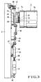
- disk-like bearers 7a are integrally formed on the two end portions of the plate cylinder 7, and a winding rod hole 7c extends in the circumferential portion of a cylinder body 7b throughout the entire length of the plate cylinder 7 between the bearers 7a.
- a plate winding rod 15 slightly longer than the length of the plate cylinder 7 and having a section of a true circle is pivotally fitted in the winding rod hole 7c.
- the movement of the plate winding rod 15 in the axial direction is regulated by abutting its stepped portions against bushes 16 fitted in corresponding portions of the bearers 7a of the winding rod hole 7c.
- a projecting portion 15a of the plate winding rod 15 on the operation side of the machine base has a hexagonal section, and a lever 17 is fixed on the projecting portion 15a by split clamping such that its hexagonal hole is fitted on the projecting portion 15a.
- An L-shaped bracket 18 is bolted to the end face of the bearer 7a close to the lever 17.
- a spring shaft 19 having a flange is pivotally fixed to the branching portion formed on the free end portion of the lever 17 by a pin 20.
- the spring shaft 19 is slidably fitted in holes respectively formed in a spring seat 21 and the bracket 18.
- Reference numeral 22 denotes a compression coil spring disposed between the flange of the spring shaft 19 and the spring seat 21 to pivot the plate winding rod 15 counterclockwise in Fig. 1 through the lever 17. As shown in Fig.
- a groove 15b is formed in the plate winding rod 15 to extend in the radial direction of the plate winding rod 15 and open to the circumferential surface of the plate winding rod 15 throughout the entire length of the plate winding rod 15.
- a plurality of U-shaped leaf springs 23 each having a small width and used for plate winding (to be described later) are urged into the groove 15b.
- the plate winding rod 15 stops as the spring force of the compression coil spring 22 and that of the leaf springs 23 are balanced.
- a gap 7d corresponding to the winding rod hole 7c is formed in the circumferential surface of the plate cylinder 7 to be open to its circumferential surface.
- the plate cylinder 7 is axially supported on the frame 2 through a bearing 24, and a pin 25 having a flange is fixed above the bearing 24 by threadably engaging its threaded portion in the screw hole in the frame 2.
- a V-shaped lever 26 is pivotally supported on the pin 25 while it is prevented from being disengaged from the pin 25 by its bush 27.
- a cam lever 28 is fixed to the other projecting portion 15a of the plate winding rod 15 by split clamping, and a cam follower 29 pivotally mounted on the central portion of the lever 26 contacts the free end portion of the cam lever 28.
- An air cylinder 31 is pivotally supported on a pin 30 provided to the frame 2.
- the operating end of a piston rod 32 which moves forward and backward by the air pressure of the air cylinder 31 and one free end portion of a V-shaped link 34 pivotally supported by a stud 33 provided to the frame 2 are coupled to each other by a link 35 having two ends pivotally supported by pins.
- the lever 26 and the other free end portion of the link 34 are coupled to each other by a link 36 having two ends pivotally supported by pins.
- a tension coil spring 39 to rotate the lever 26 to a position indicated by a solid line in Fig. 4 is provided to extend between a spring catch 37 provided to one end of the link 35 and a spring catch 38 on the frame 2.
- the tension coil spring 39 serves as a safety spring that prevents the lever 26 from being rotated to a position indicated by a long and two short dashed line in Fig. 4 when a power failure occurs.
- Reference numeral 35a denotes a stopper fixed to the frame 2 to regulate the moving limit of the link 35 when the link 35 is abutted against it.
- substantially square sub frames 41 are provided inside the two frames 2 in the vicinity of the circumferential surface of the plate cylinder 7 as they are supported by a plurality of posts 40.
- An air cylinder 42 is fixed to each sub frame 41.
- a lever 44 perpendicular to a piston rod 43 of the air cylinder 42 and extending toward substantially the axis of the blanket cylinder 4 is coupled to the operating end of the piston rod 43.
- Reference numeral 45 denotes a slide shaft having two ends supported by brackets 46 of each sub frame 41 and extending in a direction perpendicular to the lever 44. The lever 44 is slidably fitted on the slide shaft 45.
- a bearing 47 is mounted on each distal end portion of the lever 44 of each sub frame 41.
- Two end portions of a plate press roller 48 extending in the axial direction of the plate cylinder 7 are axially rotatably supported by the bearings 47 on the two sides.
- Another air cylinder 49 is fixed to each lever 44 such that its axial direction is parallel with that of the corresponding air cylinder 42.
- the air cylinders 49 move forward and backward together with the corresponding levers 44.
- a pad 51 made of an elastic material, e.g., rubber, and extending in the axial direction of the plate press roller 48 is provided to the operating end of a piston rod 50 as the pad 51 is supported by a bar 52.
- the piston rods 50 are moved forward and backward by the air pressure of the corresponding air cylinders 49.
- the free end portion of each lever 53 having a base portion pivotally loosely mounted on the end shaft of the plate press roller 48 is loosely mounted on the end shaft of the bar 52.
- the levers 53 swing about the end shaft of the plate press roller 48, and the pads 51 on the free end portions of the levers 53 are rotated to be urged against the trailing end of the plate in the radial direction. More specifically, when the plate press roller 48 is moved forward by the air cylinders 42 and urged against the plate surface, if the piston rods 50 of the air cylinders 49 are moved forward, the pads 51 are rotated to be urged against the trailing end of the plate at portions each having a different phase in the circumferential direction of the plate cylinder 7 from the portion urged by the plate press roller 48.
- a line shaft 55 driven by the driver and extending along the machine base, and an intermediate shaft 56 parallel with the line shaft 55 extend axially and are coupled to each other by gears 57 and 58.
- a solenoid clutch 59 is interposed between the gear 57 and the line shaft 55 to be connected to and disconnected from them by a signal from a control unit or a push button operation.
- the intermediate shaft 56 and a gear shaft 60 perpendicular to it are coupled by bevel gears 61 and 62, and the gear shaft 60 and the blanket cylinder 4 are coupled to each other by gears 63 and 64.
- a single-acting motor 65 is mounted to the gear box 54, and a clutch 66 for connecting and disconnecting rotary transmission between the single-acting motor 65 and the intermediate shaft 56 is provided to the intermediate shaft 56. More specifically, during printing, the intermediate shaft 56 is driven by the driver when the solenoid clutch 59 and the clutch 66 are connected and disconnected, respectively, so that the line shaft 55 is driven by the driver motor. For plate exchange, the intermediate shaft 56 is driven by the single-acting motor 65 when the solenoid clutch 59 and the clutch 66 are disconnected and connected, respectively. Referring to Fig. 8, a rotary encoder 67 is mounted in the end shaft of the upper blanket cylinder 4 opposite to the gears 13 and 14 to detect a stop position of the plate cylinder 7.
- operation panels 70 and 71 are provided to the upper and lower printing devices 3 and 5 and fixed to the frame 2 on the side of the operation space, and push buttons for operating the respective devices and units described above are provided to the operation panels 70 and 71.
- Each printing unit 1 has a sequencer of its own.
- a leading end 81a of the old plate 81 bent by a plate bending machine (not shown) is inserted in the gap 7d of the plate cylinder 7 to be held on the wall surface of the gap 7d by one end of each leaf spring 23, and a trailing end 81b of the old plate 81 bent by the plate bending machine at almost a right angle is held on the bent portion of the other end of each leaf spring 23 to be caught by it.
- a Plate exchange mode button of the operation stand is depressed to set the driver motor in a non-operative safe state, and a unit select button is depressed. Then, the solenoid clutch 59 (unit clutch) of the driver of the upper printing unit 3 of the selected printing unit 1 is disconnected, the clutch (make-ready clutch) 66 of the single-acting motor 65 is connected, and an ink clutch (not shown) is disconnected, thus resetting the printing registration apparatus for the up-down, right-left, and twisted directions to the zero position. Since the single-acting motor 65 is rotated in this state, the plate cylinder 7 is rotated to a position indicated in Fig. 12 and stopped.
- the air cylinders 42 are actuated to move the piston rods 43 forward, and the levers 44 are moved together with the pads 51 as they are guided by the slide shafts 45. Hence, the plate press roller 48 is urged against the surface of the new plate 80. Since the new plate 80 is wound on the plate cylinder 7 in this manner, it is in tight contact with the circumferential surface of the plate cylinder 7.
- a separate device is used to insert the trailing-side bent portion of the plate under the open end portions of the leaf springs 23.
- the position of the plate press roller 48 may be altered and used to insert the trailing-side bent portion of the plate.
- the plurality of leaf springs each constituted by a leaf spring member and having a U-shaped section are provided in a spring groove of the plate winding rod which is pivotally fitted in the winding rod hole of the plate cylinder and capable of being pivoted by a plate winding rod pivoting device, and the two ends of the plate mounted on the plate cylinder are held by the leaf springs.
- the plate press roller and the elastic pads are provided. The plate press roller extends in the axial direction of the plate cylinder close to the circumferential surface of the plate cylinder and is moved forward and backward toward and away from the leading end of the plate by a driving unit.
- the elastic pads extend in the axial direction of the plate cylinder close to the circumferential surface of the plate cylinder and are moved forward and backward toward and away from the trailing end of the plate by the driving unit.
- the respective devices and units are operated at predetermined timings by the control unit.
Landscapes
- Supply, Installation And Extraction Of Printed Sheets Or Plates (AREA)
- Rotary Presses (AREA)
- Manufacture Or Reproduction Of Printing Formes (AREA)
Abstract
Description
- The present invention relates to a plate exchange apparatus for a rotary press, which automatically removes an old plate from a plate cylinder and mounts a new plate on a plate cylinder.
- In a variety of rotary presses, a winding rod hole partially open to the circumferential surface of a plate cylinder and having a circular section extends in the axial direction of the plate cylinder, and a plate winding rod is fitted in the winding rod hole. To mount a plate on the circumferential surface of the plate cylinder, the leading end of the plate is inserted in the holding portion of the winding rod, and the plate cylinder is rotated by almost one revolution to wind the plate on the circumferential surface of the plate cylinder. The trailing end of the plate is held by the holding portion of the winding rod, and the plate winding rod is rotated while regulating the reverse rotation of the plate winding rod by a ratchet device or the like. To remove the plate from the plate cylinder, an operation substantially reverse to that for mounting the plate is performed.
- In a conventional plate exchange apparatus of this type, however, plate exchange must be entirely performed by manual operations necessitating much labor, thus increasing load to the operator. In addition, plate exchange requires a long period of time which prolongs the preparation time, thus degrading the operation efficiency of the machine. Also, operational safety is not sufficient.
- The present invention has been made in view of the problems described above, and has as its object to provide a plate exchange apparatus for a rotary press, which enables automatic plate exchange within a short period of time without using any tools.
- In order to achieve this object, according to the present invention, there is provided a plate exchange apparatus for a rotary press, comprising a plate winding rod pivotally fitted in a winding rod hole in an outer circumferential portion of a plate cylinder and having a spring groove extending almost the entire length thereof, a plurality of leaf springs, each constituted by a leaf spring member having a U-shaped section, provided in the spring groove, and each having an end formed with a press portion for urging a leading end of a plate against a surface of a gap of the plate cylinder and the other end formed with a bent portion for catching a bent end wound on a circumferential surface of plate cylinder, a biasing member for biasing the plate winding rod in a predetermined rotational direction, a plate winding rod pivoting unit coupled to an end portion of the plate winding rod by a cam mechanism, a plate press roller extending in an axial direction of the plate cylinder close to the circumferential surface of the plate cylinder and moved forward and backward toward and away from the leading end of the plate by a driving unit, and a control unit for operating the plate winding rod, the plurality of leaf springs, the biasing member, the plate winding rod pivoting unit, and the plate press roller at predetermined timings.
- When a start button and a selection button are depressed while the leaf springs are inserted in the groove of the plate winding rod and an old plate is mounted on the plate cylinder, the plate cylinder of a selected printing unit is stopped, the plate winding rod pivoting unit is actuated, and the plate winding rod is pivoted through the cam mechanism to let the trailing end of the old plate out of the leaf springs. The trailing end of the plate is held by a hand, and the plate cylinder is rotated in the reverse direction to remove the leading end of the plate from the leaf springs.
- After the old plate is removed in this manner, the plate winding rod is pivoted by a push button operation through the cam mechanism to insert the leading end of a new plate under the leaf springs. The plate press roller is moved forward by a push button operation to press the plate, and the plate cylinder is rotated in the forward direction to wind the new plate on its cylinder surface. Thereafter, the trailing end of the plate is inserted under the leaf springs so that its bent end is caught by the bent end portions of the leaf springs, thus completing new plate mounting.
-
- Fig. 1 is a side view of a plate cylinder;
- Fig. 2 is a partially cutaway front view of an end portion of the plate cylinder;
- Fig. 3 is a partially cutaway developed front view of a plate winding/driving section;
- Fig. 4 is a side view of the plate winding/driving section;
- Fig. 5 is a front view of a plate press section;
- Fig. 6 is a side view of the plate press section;
- Fig. 7 is a partially cutaway plan view of a printing unit single-acting driving section;
- Fig. 8 is a developed plan view of the printing unit single-acting driving section;
- Fig. 9 is a schematic plan view of a printing unit;
- Fig. 10 is a schematic front view of the printing unit;
- Fig. 11 is a front view of the plate winding rod and its vicinity to describe a plate winding operation;
- Fig. 12 is a front view of the plate winding rod and its vicinity to describe the plate winding operation;
- Fig. 13 is a front view of the plate winding rod and its vicinity to describe the plate winding operation;
- Fig. 14 is a front view of the plate winding rod and its vicinity to describe the plate winding operation;
- Fig. 15 is a front view of the plate winding rod and its vicinity to describe the plate winding operation;
- Fig. 16 is a side view of an end portion of the plate cylinder and its vicinity to describe the plate winding operation;
- Fig. 17 is a side view of the end portion of the plate cylinder and its vicinity to describe the plate winding operation;
- Fig. 18 is a side view of the end portion of the plate cylinder and its vicinity to describe the plate winding operation;
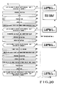
- Fig. 19 is a flow chart of a plate exchange operation;
- Fig. 20 is a flow chart of the plate exchange operation; and
- Fig. 21 is a flow chart of the plate exchange operation.
- Figs. 1 to 18 show an arrangement in which a plate exchange apparatus for a rotary press according to the present invention is applied to a perfecting web rotary press, in which Fig. 1 shows a plate cylinder, Fig. 2 shows an end portion of the plate cylinder, Figs. 3 and 4 show a plate winding/driving section, Figs. 5 and 6 show a plate press section, Figs. 7 and 8 show a printing unit single-acting section, Figs. 9 and 10 show a printing unit, Figs. 11 to 15 show a plate winding rod and its vicinity to describe a plate winding operation, and Figs. 16 to 18 show an end portion of the plate cylinder and its vicinity to describe the plate winding operation. Figs. 19 to 21 show a plate exchange operation.
- Referring to Figs. 8 to 10, a
blanket cylinder 4 of anupper printing device 3 and ablanket cylinder 6 of alower printing device 5 are axially supported to extend between right andleft frames 2 of aprinting unit 1 to be in contact with each other.Plate cylinders left frames 2 contact theblanket cylinders plate cylinders lower printing device 5 has substantially the same arrangement as that of theupper printing device 3, and hence only theupper printing device 3 will be described hereinafter. A plurality ofink rollers 9 of an inking arrangement shown in Fig. 6 contact the surface of the plate mounted on theplate cylinder 7, and aform dampening roller 10 of a dampening arrangement contacts the surface of the plate. Images formed on the plate surfaces with ink and water supplied to the plate surface from the inking and dampening arrangements only partly shown in Fig. 6 are transferred to theblanket cylinders web 11 travelling in a direction indicated by an arrow in Fig. 10, thus performing double-sided printing.Reference numerals 12 denote steps provided betweenadjacent printing units 1. The operator stands on eachstep 12 to perform plate exchange, ink exchange, or the like.Reference numerals blanket cylinders plate cylinders - Referring to Figs. 1 and 2, disk-
like bearers 7a are integrally formed on the two end portions of theplate cylinder 7, and awinding rod hole 7c extends in the circumferential portion of acylinder body 7b throughout the entire length of theplate cylinder 7 between thebearers 7a. Aplate winding rod 15 slightly longer than the length of theplate cylinder 7 and having a section of a true circle is pivotally fitted in the windingrod hole 7c. The movement of theplate winding rod 15 in the axial direction is regulated by abutting its stepped portions againstbushes 16 fitted in corresponding portions of thebearers 7a of thewinding rod hole 7c. A projectingportion 15a of theplate winding rod 15 on the operation side of the machine base has a hexagonal section, and alever 17 is fixed on the projectingportion 15a by split clamping such that its hexagonal hole is fitted on the projectingportion 15a. - An L-
shaped bracket 18 is bolted to the end face of thebearer 7a close to thelever 17. Aspring shaft 19 having a flange is pivotally fixed to the branching portion formed on the free end portion of thelever 17 by apin 20. Thespring shaft 19 is slidably fitted in holes respectively formed in aspring seat 21 and thebracket 18.Reference numeral 22 denotes a compression coil spring disposed between the flange of thespring shaft 19 and thespring seat 21 to pivot theplate winding rod 15 counterclockwise in Fig. 1 through thelever 17. As shown in Fig. 11, agroove 15b is formed in theplate winding rod 15 to extend in the radial direction of theplate winding rod 15 and open to the circumferential surface of theplate winding rod 15 throughout the entire length of theplate winding rod 15. A plurality ofU-shaped leaf springs 23 each having a small width and used for plate winding (to be described later) are urged into thegroove 15b. Theplate winding rod 15 stops as the spring force of thecompression coil spring 22 and that of theleaf springs 23 are balanced. Agap 7d corresponding to thewinding rod hole 7c is formed in the circumferential surface of theplate cylinder 7 to be open to its circumferential surface. - Referring to Figs. 3 and 4, the
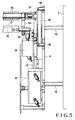
plate cylinder 7 is axially supported on theframe 2 through abearing 24, and apin 25 having a flange is fixed above thebearing 24 by threadably engaging its threaded portion in the screw hole in theframe 2. A V-shaped lever 26 is pivotally supported on thepin 25 while it is prevented from being disengaged from thepin 25 by itsbush 27. Acam lever 28 is fixed to the other projectingportion 15a of theplate winding rod 15 by split clamping, and acam follower 29 pivotally mounted on the central portion of thelever 26 contacts the free end portion of thecam lever 28. - An
air cylinder 31 is pivotally supported on apin 30 provided to theframe 2. The operating end of apiston rod 32 which moves forward and backward by the air pressure of theair cylinder 31 and one free end portion of a V-shapedlink 34 pivotally supported by astud 33 provided to theframe 2 are coupled to each other by alink 35 having two ends pivotally supported by pins. Thelever 26 and the other free end portion of thelink 34 are coupled to each other by alink 36 having two ends pivotally supported by pins. Atension coil spring 39 to rotate thelever 26 to a position indicated by a solid line in Fig. 4 is provided to extend between aspring catch 37 provided to one end of thelink 35 and aspring catch 38 on theframe 2. Thetension coil spring 39 serves as a safety spring that prevents thelever 26 from being rotated to a position indicated by a long and two short dashed line in Fig. 4 when a power failure occurs.Reference numeral 35a denotes a stopper fixed to theframe 2 to regulate the moving limit of thelink 35 when thelink 35 is abutted against it. - Referring to Figs. 5 and 6, substantially square sub frames 41 are provided inside the two
frames 2 in the vicinity of the circumferential surface of theplate cylinder 7 as they are supported by a plurality ofposts 40. Anair cylinder 42 is fixed to eachsub frame 41. Alever 44 perpendicular to apiston rod 43 of theair cylinder 42 and extending toward substantially the axis of theblanket cylinder 4 is coupled to the operating end of thepiston rod 43.Reference numeral 45 denotes a slide shaft having two ends supported bybrackets 46 of eachsub frame 41 and extending in a direction perpendicular to thelever 44. Thelever 44 is slidably fitted on theslide shaft 45. When thepiston rod 43 is moved forward and backward by the air pressure, thelever 44 is guided by theslide shaft 45 to move forward and backward toward and away from the circumferential surface of theplate cylinder 7. Abearing 47 is mounted on each distal end portion of thelever 44 of eachsub frame 41. Two end portions of aplate press roller 48 extending in the axial direction of theplate cylinder 7 are axially rotatably supported by thebearings 47 on the two sides. When theplate press roller 48 is moved forward, it is brought into tight contact with the plate surface on theplate cylinder 7. - Another
air cylinder 49 is fixed to eachlever 44 such that its axial direction is parallel with that of thecorresponding air cylinder 42. Theair cylinders 49 move forward and backward together with the correspondinglevers 44. Apad 51 made of an elastic material, e.g., rubber, and extending in the axial direction of theplate press roller 48 is provided to the operating end of apiston rod 50 as thepad 51 is supported by abar 52. Thepiston rods 50 are moved forward and backward by the air pressure of thecorresponding air cylinders 49. The free end portion of eachlever 53 having a base portion pivotally loosely mounted on the end shaft of theplate press roller 48 is loosely mounted on the end shaft of thebar 52. When thepiston rods 50 are moved forward, thelevers 53 swing about the end shaft of theplate press roller 48, and thepads 51 on the free end portions of thelevers 53 are rotated to be urged against the trailing end of the plate in the radial direction. More specifically, when theplate press roller 48 is moved forward by theair cylinders 42 and urged against the plate surface, if thepiston rods 50 of theair cylinders 49 are moved forward, thepads 51 are rotated to be urged against the trailing end of the plate at portions each having a different phase in the circumferential direction of theplate cylinder 7 from the portion urged by theplate press roller 48. - The arrangement of the printing unit driving section will be described with reference to Fig. 7. In a
gear box 54 provided to the driver of theprinting unit 1, aline shaft 55, driven by the driver and extending along the machine base, and anintermediate shaft 56 parallel with theline shaft 55 extend axially and are coupled to each other bygears solenoid clutch 59 is interposed between thegear 57 and theline shaft 55 to be connected to and disconnected from them by a signal from a control unit or a push button operation. Theintermediate shaft 56 and agear shaft 60 perpendicular to it are coupled bybevel gears gear shaft 60 and theblanket cylinder 4 are coupled to each other bygears - A single-acting
motor 65 is mounted to thegear box 54, and a clutch 66 for connecting and disconnecting rotary transmission between the single-actingmotor 65 and theintermediate shaft 56 is provided to theintermediate shaft 56. More specifically, during printing, theintermediate shaft 56 is driven by the driver when thesolenoid clutch 59 and the clutch 66 are connected and disconnected, respectively, so that theline shaft 55 is driven by the driver motor. For plate exchange, theintermediate shaft 56 is driven by the single-actingmotor 65 when thesolenoid clutch 59 and the clutch 66 are disconnected and connected, respectively. Referring to Fig. 8, arotary encoder 67 is mounted in the end shaft of theupper blanket cylinder 4 opposite to thegears plate cylinder 7. - Referring to Fig. 10,
operation panels lower printing devices frame 2 on the side of the operation space, and push buttons for operating the respective devices and units described above are provided to theoperation panels printing unit 1 has a sequencer of its own. - The operation of the plate exchange apparatus having the arrangement as described above will be described with reference to the views of Figs. 11 to 18 describing the plate winding operation and the flow charts of Figs. 19 to 21. The leaf springs 23 are urged in the
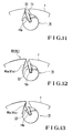
groove 15b of theplate winding rod 15, and anold plate 81 is mounted on theplate cylinder 7 in the same manner as anew plate 80 shown in Fig. 15. More specifically, aleading end 81a of theold plate 81 bent by a plate bending machine (not shown) is inserted in thegap 7d of theplate cylinder 7 to be held on the wall surface of thegap 7d by one end of eachleaf spring 23, and a trailingend 81b of theold plate 81 bent by the plate bending machine at almost a right angle is held on the bent portion of the other end of eachleaf spring 23 to be caught by it. - When the old plate is mounted in this manner, a Plate exchange mode button of the operation stand is depressed to set the driver motor in a non-operative safe state, and a unit select button is depressed. Then, the solenoid clutch 59 (unit clutch) of the driver of the
upper printing unit 3 of the selectedprinting unit 1 is disconnected, the clutch (make-ready clutch) 66 of the single-actingmotor 65 is connected, and an ink clutch (not shown) is disconnected, thus resetting the printing registration apparatus for the up-down, right-left, and twisted directions to the zero position. Since the single-actingmotor 65 is rotated in this state, theplate cylinder 7 is rotated to a position indicated in Fig. 12 and stopped. - In this state, when a preparation/operation button is depressed, the
air cylinder 31 is actuated, thecam follower 29 pivotally supported on thelever 26 urges thecam lever 28 to pivot theplate winding rod 15, as shown in Fig. 17, and the bent portions of theleaf springs 23 release theold plate 81, as shown in Fig. 14. Hence, the trailing-side bent portion of theold plate 81 is let out of theplate cylinder 7. When the trailing end of theplate 81 is held by hand and the preparation/operation button is depressed, theplate cylinder 7 is rotated in the reverse direction to rewind theold plate 81, and is stopped at the position shown in Fig. 18. - Then, when the preparation/operation button is depressed, the
air cylinder 31 is actuated so that thecam follower 29 pivotally mounted on thelever 26 urges thecam lever 28 to rotate theplate winding rod 15 to and stop it at the position shown in Fig. 12. The leading end of theold plate 81 is released from theleaf springs 23 and is let out of theplate cylinder 7, thus completing removal of theold plate 81. - In this state, when a
leading end 80a of thenew plate 80 is inserted in the gap of theblanket cylinder 4, as shown in Fig. 12, and the preparation/operation button is depressed, theair cylinder 31 is actuated so that thecam follower 29 pivotally mounted on thelever 26 releases thecam lever 28, and theplate winding rod 15 is rotated to and stopped at the position shown in Fig. 13 by the spring force of thecompression coil spring 22. Hence, theleading end 80a of thenew plate 80 is held by the leaf springs 23. When the preparation/operation button is depressed, theplate cylinder 7 is rotated in the forward direction to wind thenew plate 80 on the circumferential surface of theplate cylinder 7, and theplate cylinder 7 is stopped at the position shown in Fig. 17. When thenew plate 80 is to be wound on the circumferential surface of theplate cylinder 7, theair cylinders 42 are actuated to move thepiston rods 43 forward, and thelevers 44 are moved together with thepads 51 as they are guided by theslide shafts 45. Hence, theplate press roller 48 is urged against the surface of thenew plate 80. Since thenew plate 80 is wound on theplate cylinder 7 in this manner, it is in tight contact with the circumferential surface of theplate cylinder 7. - When the rotation of the
plate cylinder 7 is stopped, theair cylinders 49 are actuated to move theirpiston rods 50 forward. Then, thelevers 53 are pivoted about the end shaft of theplate press roller 48 to rotate thepads 51 fixed to their free end portions to be urged against the trailing-side bent portion of thenew plate 80 in the radial direction. Thus, the trailing-side bent portion of thenew plate 80 is inserted under the open end portions of the leaf springs 23. At this time, theplate winding rod 15 is pivoted by theair cylinders 42 to the position shown in Fig. 15. Thus, a trailing-side end portion 80b of thenew plate 80 is held as itsbent end 80c is caught by the bent portions of theleaf springs 23, thus completing mounting of thenew plate 80. After this, plate exchange of thelower printing device 5 and plate exchange of other printing units are performed in accordance with the same operation as that described above. Clutch exchange is performed, and the plate exchange mode button is cancelled. - In the above embodiment, a separate device is used to insert the trailing-side bent portion of the plate under the open end portions of the leaf springs 23. However, the position of the
plate press roller 48 may be altered and used to insert the trailing-side bent portion of the plate. - As is apparent from the above description, according to the present invention, the plurality of leaf springs each constituted by a leaf spring member and having a U-shaped section are provided in a spring groove of the plate winding rod which is pivotally fitted in the winding rod hole of the plate cylinder and capable of being pivoted by a plate winding rod pivoting device, and the two ends of the plate mounted on the plate cylinder are held by the leaf springs. The plate press roller and the elastic pads are provided. The plate press roller extends in the axial direction of the plate cylinder close to the circumferential surface of the plate cylinder and is moved forward and backward toward and away from the leading end of the plate by a driving unit. The elastic pads extend in the axial direction of the plate cylinder close to the circumferential surface of the plate cylinder and are moved forward and backward toward and away from the trailing end of the plate by the driving unit. The respective devices and units are operated at predetermined timings by the control unit. Hence, the plate exchange operation can be performed by a single operator within a short period of time without using any tool to decrease labor and energy consumption, thereby shortening the preparation time and increasing the operation efficiency of the machine.
Claims (1)
- A plate exchange apparatus for a rotary press,
characterized by comprising:
a plate winding rod (15) pivotally fitted in a winding rod hole (7c) in an outer circumferential portion of a plate cylinder (7; 8) and having a spring groove (15b) extending almost an entire length thereof;
a plurality of leaf springs (23), each constituted by a leaf spring member to have a U-shaped section, provided in the spring groove (15b), and each having an end formed with a press portion for urging a leading end (80a; 81a) of a plate (80; 81) against a surface of a gap (7d) of said plate cylinder (7; 8) and the other end formed with a bent portion for catching a bent end (80c; 81c) of the plate (80; 81) wound on a circumferential surface of said plate cylinder (7; 8);
a biasing member (22) for biasing said plate winding rod (15) in a predetermined rotational direction;
a plate winding rod pivoting unit (26) coupled to an end portion (15a) of said plate winding rod (15) by a cam mechanism (28, 29);
a plate press roller (48) extending in an axial direction of said plate cylinder (7; 8) close to said circumferential surface of said plate cylinder (7; 8) and moved forward and backward toward and away from the leading end (80a; 81a) of the plate (80; 81) by a driving unit (42); and
a control unit for operating said plate winding rod (15), said plurality of leaf springs (23), said biasing member (22), said plate winding rod pivoting unit (26), and said plate press roller (48) at predetermined timings.
Applications Claiming Priority (2)
| Application Number | Priority Date | Filing Date | Title |
|---|---|---|---|
| JP266986/91 | 1991-09-19 | ||
| JP3266986A JP3030582B2 (en) | 1991-09-19 | 1991-09-19 | Plate changing device for rotary printing press |
Publications (4)
| Publication Number | Publication Date |
|---|---|
| EP0534579A2 EP0534579A2 (en) | 1993-03-31 |
| EP0534579A3 EP0534579A3 (en) | 1993-06-09 |
| EP0534579B1 true EP0534579B1 (en) | 1996-06-26 |
| EP0534579B2 EP0534579B2 (en) | 1999-04-28 |
Family
ID=17438474
Family Applications (1)
| Application Number | Title | Priority Date | Filing Date |
|---|---|---|---|
| EP92250266A Expired - Lifetime EP0534579B2 (en) | 1991-09-19 | 1992-09-18 | Plate exchange apparatus for rotary press |
Country Status (5)
| Country | Link |
|---|---|
| US (1) | US5213038A (en) |
| EP (1) | EP0534579B2 (en) |
| JP (1) | JP3030582B2 (en) |
| AT (1) | ATE139736T1 (en) |
| DE (1) | DE69211797T3 (en) |
Families Citing this family (19)
| Publication number | Priority date | Publication date | Assignee | Title |
|---|---|---|---|---|
| DE4225949C2 (en) * | 1992-08-06 | 1994-10-13 | Roland Man Druckmasch | Device for attaching a flexible pressure plate |
| DE4234332A1 (en) * | 1992-10-12 | 1994-04-14 | Heidelberger Druckmasch Ag | Clamping device for attaching a flexible printing form to the outer surface of a cylinder |
| DE4300099C1 (en) * | 1993-01-05 | 1993-12-16 | Heidelberger Druckmasch Ag | Clamping device with parallel clamping surfaces |
| FR2709091B1 (en) * | 1993-08-20 | 1995-11-10 | Heidelberg Harris Sa | Interchangeable blade device for holding a printing plate on a plate cylinder in a rotary printer, and blade disassembly tool. |
| DE4330610A1 (en) * | 1993-09-09 | 1995-03-16 | Roland Man Druckmasch | Sheet gripper for a sheet processing machine |
| DE4335140C1 (en) * | 1993-10-15 | 1995-02-02 | Roland Man Druckmasch | Device for attaching a flexible printing plate |
| DE4415683C2 (en) * | 1994-05-04 | 1998-04-09 | Roland Man Druckmasch | Device for attaching a flexible pressure plate |
| DE19701046C5 (en) * | 1996-01-19 | 2008-04-10 | Man Roland Druckmaschinen Ag | Device for fastening a clothing on a printing cylinder |
| DE29600845U1 (en) * | 1996-01-19 | 1996-03-07 | MAN Roland Druckmaschinen AG, 63075 Offenbach | Device for fastening a covering on a printing unit cylinder |
| CN1082689C (en) * | 1996-02-07 | 2002-04-10 | 凌阳科技股份有限公司 | Virtual multiplex microprocessor |
| DE19611642C2 (en) * | 1996-03-25 | 2002-07-18 | Roland Man Druckmasch | Device for fastening a covering on a printing unit cylinder |
| EP1038672B1 (en) * | 1999-03-26 | 2003-12-03 | Heidelberger Druckmaschinen Aktiengesellschaft | Device for tensioning of printing plates in lock-up gaps having a reduced size |
| DE19913701A1 (en) * | 1999-03-26 | 2000-09-28 | Heidelberger Druckmasch Ag | Printing plate mounting system, using spring fittings engaging with rear edge of plate and allowing play |
| DE10060826A1 (en) * | 2000-12-07 | 2002-06-13 | Heidelberger Druckmasch Ag | Spring element for fixing printing forms to printing form cylinders |
| DE10060984B4 (en) * | 2000-12-08 | 2006-10-26 | Man Roland Druckmaschinen Ag | Vorichtung for attaching a clothing on a printing cylinder |
| EP1790472A3 (en) * | 2005-11-02 | 2008-05-07 | Goss Systemes Graphiques Nantes | Printing press with plate locking mechanisms mounted on the frame |
| FR2892660B1 (en) * | 2005-11-02 | 2012-05-25 | Goss Systemes Graphiques Nantes | PRINTING PRESS WITH LOCKING ACTUATORS OF PLATES FITTED BY THE BUILDING. |
| FR2905082B1 (en) * | 2006-08-22 | 2010-01-22 | Goss Int Montataire Sa | PRINTING PLATE AND CORRESPONDING PRINTING ASSEMBLY. |
| KR200495660Y1 (en) * | 2020-09-23 | 2022-07-20 | 아이디어링크 주식회사 | Apparatus for training golf with motion sensing circuit board |
Family Cites Families (12)
| Publication number | Priority date | Publication date | Assignee | Title |
|---|---|---|---|---|
| US3626848A (en) * | 1969-06-09 | 1971-12-14 | American Rockwell Corp | Lockup for thin plates |
| US3727551A (en) * | 1971-07-22 | 1973-04-17 | North American Rockwell | Reversible lockup for flexible printing plate |
| GB1486873A (en) * | 1974-08-06 | 1977-09-28 | Koenig & Bauer Ag | Printing press cylinder with means of securing a mounting block for a printing plate or blanket clamping device |
| US4104968A (en) * | 1976-06-03 | 1978-08-08 | Albert-Frankenthal Ag | Clamping device for flexible printing plates |
| US4347788A (en) * | 1980-05-01 | 1982-09-07 | Harris Corporation | Plate lockup mechanism |
| DE3018249C2 (en) * | 1980-05-13 | 1982-09-09 | M.A.N.- Roland Druckmaschinen AG, 6050 Offenbach | Device for attaching flexible printing plates to the plate cylinder of rotary printing presses |
| DE3315445A1 (en) * | 1983-04-28 | 1984-10-31 | M.A.N.- Roland Druckmaschinen AG, 6050 Offenbach | PROTECTING THE TRANSITION |
| US4493258A (en) * | 1983-11-14 | 1985-01-15 | Rockwell International Corporation | Interfacing cam and toggle lockup |
| JP2726661B2 (en) * | 1986-09-18 | 1998-03-11 | 三菱重工業株式会社 | Plate insertion device for sheet-fed printing press |
| US4890555A (en) * | 1987-06-03 | 1990-01-02 | Motter Printing Press Co. | Printing press plate lockup |
| US5107763A (en) * | 1990-04-24 | 1992-04-28 | Rockwell International Corporation | Narrow gap plate mounting apparatus and method |
| US5131326A (en) * | 1991-08-19 | 1992-07-21 | Rockwell International Corporation | Cover mounting for a printing press |
-
1991
- 1991-09-19 JP JP3266986A patent/JP3030582B2/en not_active Expired - Fee Related
-
1992
- 1992-09-16 US US07/945,692 patent/US5213038A/en not_active Expired - Fee Related
- 1992-09-18 AT AT92250266T patent/ATE139736T1/en not_active IP Right Cessation
- 1992-09-18 EP EP92250266A patent/EP0534579B2/en not_active Expired - Lifetime
- 1992-09-18 DE DE69211797T patent/DE69211797T3/en not_active Expired - Lifetime
Also Published As
| Publication number | Publication date |
|---|---|
| DE69211797T2 (en) | 1997-02-06 |
| JP3030582B2 (en) | 2000-04-10 |
| DE69211797T3 (en) | 2000-01-05 |
| EP0534579B2 (en) | 1999-04-28 |
| JPH0577399A (en) | 1993-03-30 |
| US5213038A (en) | 1993-05-25 |
| EP0534579A2 (en) | 1993-03-31 |
| EP0534579A3 (en) | 1993-06-09 |
| DE69211797D1 (en) | 1996-08-01 |
| ATE139736T1 (en) | 1996-07-15 |
Similar Documents
| Publication | Publication Date | Title |
|---|---|---|
| EP0534579B1 (en) | Plate exchange apparatus for rotary press | |
| JP3117592B2 (en) | Printing device capable of releasing bearing tightening | |
| DE2833745C2 (en) | Device for feeding a flexible printing plate to a plate cylinder | |
| EP0516260B1 (en) | Apparatus for mounting plate on plate cylinder | |
| JPH11334029A (en) | Flexographic rotary printing press and temporary engagement device thereof | |
| US20180079198A1 (en) | Variable Cutoff Printing Press with Off Impression Gap | |
| JP2911815B2 (en) | Equipment for grooming and escape | |
| EP0551166B1 (en) | Plate exchange apparatus for printing press | |
| US7963226B2 (en) | Method for operating a printing unit having at least one press unit, and a press unit for carrying out the method | |
| US7934450B2 (en) | Printing press | |
| AU748606B2 (en) | Positioning device of a flexible printing plate on a plate cylinder | |
| EP2722176A2 (en) | Variable cutoff printing press with actuators for moving blanket and impression cylinder supports | |
| JP3220909B2 (en) | Plate press device of rotary printing press. | |
| JP2579079B2 (en) | Device for supporting the impression cylinder of a rotary printing press | |
| EP0519583B2 (en) | Plate exchange apparatus for printing press | |
| JP3030583B2 (en) | Plate drive for rotary printing press | |
| EP0445600A2 (en) | Cylinder cleaning mechanism for a printing press | |
| US20010042478A1 (en) | Printing press | |
| EP0895859B1 (en) | Lifting device for ink form rollers in a printing machine | |
| US20010042470A1 (en) | Printing press | |
| JPH0577400A (en) | Pressplate replacing method and device in rotary press | |
| JP2008534330A (en) | Web offset printing machine with pivoted tacker | |
| US5688068A (en) | Phase adjustment fixing apparatus for cam | |
| JPH0446236B2 (en) | ||
| EP0774353A1 (en) | Offset printing machine |
Legal Events
| Date | Code | Title | Description |
|---|---|---|---|
| PUAI | Public reference made under article 153(3) epc to a published international application that has entered the european phase |
Free format text: ORIGINAL CODE: 0009012 |
|
| 17P | Request for examination filed |
Effective date: 19921014 |
|
| AK | Designated contracting states |
Kind code of ref document: A2 Designated state(s): AT CH DE FR GB IT LI NL SE |
|
| PUAL | Search report despatched |
Free format text: ORIGINAL CODE: 0009013 |
|
| AK | Designated contracting states |
Kind code of ref document: A3 Designated state(s): AT CH DE FR GB IT LI NL SE |
|
| 17Q | First examination report despatched |
Effective date: 19950728 |
|
| GRAH | Despatch of communication of intention to grant a patent |
Free format text: ORIGINAL CODE: EPIDOS IGRA |
|
| GRAA | (expected) grant |
Free format text: ORIGINAL CODE: 0009210 |
|
| AK | Designated contracting states |
Kind code of ref document: B1 Designated state(s): AT CH DE FR GB IT LI NL SE |
|
| REF | Corresponds to: |
Ref document number: 139736 Country of ref document: AT Date of ref document: 19960715 Kind code of ref document: T |
|
| REF | Corresponds to: |
Ref document number: 69211797 Country of ref document: DE Date of ref document: 19960801 |
|
| ET | Fr: translation filed | ||
| ITF | It: translation for a ep patent filed | ||
| REG | Reference to a national code |
Ref country code: CH Ref legal event code: NV Representative=s name: PATENTANWALTSBUREAU BOSSHARD UND LUCHS |
|
| PLBI | Opposition filed |
Free format text: ORIGINAL CODE: 0009260 |
|
| PLBF | Reply of patent proprietor to notice(s) of opposition |
Free format text: ORIGINAL CODE: EPIDOS OBSO |
|
| 26 | Opposition filed |
Opponent name: KBA KOENIG & BAUER-ALBERT AG WERK WUERZBURG Effective date: 19970325 |
|
| NLR1 | Nl: opposition has been filed with the epo |
Opponent name: KBA KOENIG & BAUER-ALBERT AG WERK WUERZBURG |
|
| PLBF | Reply of patent proprietor to notice(s) of opposition |
Free format text: ORIGINAL CODE: EPIDOS OBSO |
|
| PLAW | Interlocutory decision in opposition |
Free format text: ORIGINAL CODE: EPIDOS IDOP |
|
| PLAW | Interlocutory decision in opposition |
Free format text: ORIGINAL CODE: EPIDOS IDOP |
|
| PUAH | Patent maintained in amended form |
Free format text: ORIGINAL CODE: 0009272 |
|
| STAA | Information on the status of an ep patent application or granted ep patent |
Free format text: STATUS: PATENT MAINTAINED AS AMENDED |
|
| 27A | Patent maintained in amended form |
Effective date: 19990428 |
|
| AK | Designated contracting states |
Kind code of ref document: B2 Designated state(s): AT CH DE FR GB IT LI NL SE |
|
| REG | Reference to a national code |
Ref country code: CH Ref legal event code: AEN Free format text: AUFRECHTERHALTUNG DES PATENTES IN GEAENDERTER FORM |
|
| ET3 | Fr: translation filed ** decision concerning opposition | ||
| NLR2 | Nl: decision of opposition | ||
| NLR3 | Nl: receipt of modified translations in the netherlands language after an opposition procedure | ||
| REG | Reference to a national code |
Ref country code: GB Ref legal event code: IF02 |
|
| PGFP | Annual fee paid to national office [announced via postgrant information from national office to epo] |
Ref country code: FR Payment date: 20080915 Year of fee payment: 17 Ref country code: NL Payment date: 20080915 Year of fee payment: 17 Ref country code: AT Payment date: 20080912 Year of fee payment: 17 Ref country code: IT Payment date: 20080926 Year of fee payment: 17 |
|
| PGFP | Annual fee paid to national office [announced via postgrant information from national office to epo] |
Ref country code: GB Payment date: 20080924 Year of fee payment: 17 |
|
| PGFP | Annual fee paid to national office [announced via postgrant information from national office to epo] |
Ref country code: CH Payment date: 20081016 Year of fee payment: 17 |
|
| PGFP | Annual fee paid to national office [announced via postgrant information from national office to epo] |
Ref country code: SE Payment date: 20080908 Year of fee payment: 17 |
|
| PGFP | Annual fee paid to national office [announced via postgrant information from national office to epo] |
Ref country code: DE Payment date: 20090910 Year of fee payment: 18 |
|
| REG | Reference to a national code |
Ref country code: NL Ref legal event code: V1 Effective date: 20100401 |
|
| REG | Reference to a national code |
Ref country code: CH Ref legal event code: PL |
|
| EUG | Se: european patent has lapsed | ||
| GBPC | Gb: european patent ceased through non-payment of renewal fee |
Effective date: 20090918 |
|
| REG | Reference to a national code |
Ref country code: FR Ref legal event code: ST Effective date: 20100531 |
|
| PG25 | Lapsed in a contracting state [announced via postgrant information from national office to epo] |
Ref country code: AT Free format text: LAPSE BECAUSE OF NON-PAYMENT OF DUE FEES Effective date: 20090918 |
|
| PG25 | Lapsed in a contracting state [announced via postgrant information from national office to epo] |
Ref country code: FR Free format text: LAPSE BECAUSE OF NON-PAYMENT OF DUE FEES Effective date: 20090930 Ref country code: NL Free format text: LAPSE BECAUSE OF NON-PAYMENT OF DUE FEES Effective date: 20100401 |
|
| PG25 | Lapsed in a contracting state [announced via postgrant information from national office to epo] |
Ref country code: LI Free format text: LAPSE BECAUSE OF NON-PAYMENT OF DUE FEES Effective date: 20090930 Ref country code: CH Free format text: LAPSE BECAUSE OF NON-PAYMENT OF DUE FEES Effective date: 20090930 |
|
| PG25 | Lapsed in a contracting state [announced via postgrant information from national office to epo] |
Ref country code: GB Free format text: LAPSE BECAUSE OF NON-PAYMENT OF DUE FEES Effective date: 20090918 |
|
| PG25 | Lapsed in a contracting state [announced via postgrant information from national office to epo] |
Ref country code: IT Free format text: LAPSE BECAUSE OF NON-PAYMENT OF DUE FEES Effective date: 20090918 |
|
| PG25 | Lapsed in a contracting state [announced via postgrant information from national office to epo] |
Ref country code: SE Free format text: LAPSE BECAUSE OF NON-PAYMENT OF DUE FEES Effective date: 20090919 |
|
| REG | Reference to a national code |
Ref country code: DE Ref legal event code: R119 Ref document number: 69211797 Country of ref document: DE Effective date: 20110401 |
|
| PG25 | Lapsed in a contracting state [announced via postgrant information from national office to epo] |
Ref country code: DE Free format text: LAPSE BECAUSE OF NON-PAYMENT OF DUE FEES Effective date: 20110401 |