EP0534232A1 - Einrichtung und Verfahren zur Verbindung der SRM-Zwischenleitungen - Google Patents
Einrichtung und Verfahren zur Verbindung der SRM-Zwischenleitungen Download PDFInfo
- Publication number
- EP0534232A1 EP0534232A1 EP19920115427 EP92115427A EP0534232A1 EP 0534232 A1 EP0534232 A1 EP 0534232A1 EP 19920115427 EP19920115427 EP 19920115427 EP 92115427 A EP92115427 A EP 92115427A EP 0534232 A1 EP0534232 A1 EP 0534232A1
- Authority
- EP
- European Patent Office
- Prior art keywords
- highways
- srm
- vertical
- row
- inter
- Prior art date
- Legal status (The legal status is an assumption and is not a legal conclusion. Google has not performed a legal analysis and makes no representation as to the accuracy of the status listed.)
- Withdrawn
Links
Images


Classifications
-
- H—ELECTRICITY
- H04—ELECTRIC COMMUNICATION TECHNIQUE
- H04L—TRANSMISSION OF DIGITAL INFORMATION, e.g. TELEGRAPHIC COMMUNICATION
- H04L12/00—Data switching networks
- H04L12/54—Store-and-forward switching systems
- H04L12/56—Packet switching systems
- H04L12/5601—Transfer mode dependent, e.g. ATM
-
- H—ELECTRICITY
- H04—ELECTRIC COMMUNICATION TECHNIQUE
- H04L—TRANSMISSION OF DIGITAL INFORMATION, e.g. TELEGRAPHIC COMMUNICATION
- H04L49/00—Packet switching elements
- H04L49/10—Packet switching elements characterised by the switching fabric construction
- H04L49/104—Asynchronous transfer mode [ATM] switching fabrics
- H04L49/105—ATM switching elements
- H04L49/106—ATM switching elements using space switching, e.g. crossbar or matrix
-
- H—ELECTRICITY
- H04—ELECTRIC COMMUNICATION TECHNIQUE
- H04L—TRANSMISSION OF DIGITAL INFORMATION, e.g. TELEGRAPHIC COMMUNICATION
- H04L49/00—Packet switching elements
- H04L49/15—Interconnection of switching modules
- H04L49/1553—Interconnection of ATM switching modules, e.g. ATM switching fabrics
-
- H—ELECTRICITY
- H04—ELECTRIC COMMUNICATION TECHNIQUE
- H04Q—SELECTING
- H04Q3/00—Selecting arrangements
- H04Q3/64—Distributing or queueing
- H04Q3/68—Grouping or interlacing selector groups or stages
- H04Q3/685—Circuit arrangements therefor
-
- H—ELECTRICITY
- H04—ELECTRIC COMMUNICATION TECHNIQUE
- H04L—TRANSMISSION OF DIGITAL INFORMATION, e.g. TELEGRAPHIC COMMUNICATION
- H04L12/00—Data switching networks
- H04L12/54—Store-and-forward switching systems
- H04L12/56—Packet switching systems
- H04L12/5601—Transfer mode dependent, e.g. ATM
- H04L2012/5638—Services, e.g. multimedia, GOS, QOS
- H04L2012/5646—Cell characteristics, e.g. loss, delay, jitter, sequence integrity
- H04L2012/5649—Cell delay or jitter
-
- H—ELECTRICITY
- H04—ELECTRIC COMMUNICATION TECHNIQUE
- H04L—TRANSMISSION OF DIGITAL INFORMATION, e.g. TELEGRAPHIC COMMUNICATION
- H04L12/00—Data switching networks
- H04L12/54—Store-and-forward switching systems
- H04L12/56—Packet switching systems
- H04L12/5601—Transfer mode dependent, e.g. ATM
- H04L2012/5638—Services, e.g. multimedia, GOS, QOS
- H04L2012/5646—Cell characteristics, e.g. loss, delay, jitter, sequence integrity
- H04L2012/5651—Priority, marking, classes
-
- H—ELECTRICITY
- H04—ELECTRIC COMMUNICATION TECHNIQUE
- H04L—TRANSMISSION OF DIGITAL INFORMATION, e.g. TELEGRAPHIC COMMUNICATION
- H04L12/00—Data switching networks
- H04L12/54—Store-and-forward switching systems
- H04L12/56—Packet switching systems
- H04L12/5601—Transfer mode dependent, e.g. ATM
- H04L2012/5672—Multiplexing, e.g. coding, scrambling
-
- H—ELECTRICITY
- H04—ELECTRIC COMMUNICATION TECHNIQUE
- H04L—TRANSMISSION OF DIGITAL INFORMATION, e.g. TELEGRAPHIC COMMUNICATION
- H04L12/00—Data switching networks
- H04L12/54—Store-and-forward switching systems
- H04L12/56—Packet switching systems
- H04L12/5601—Transfer mode dependent, e.g. ATM
- H04L2012/5678—Traffic aspects, e.g. arbitration, load balancing, smoothing, buffer management
- H04L2012/5681—Buffer or queue management
Definitions
- This invention pertains to a highway connection between SRMs (Self Routing Modules), which are switching modules for a broadband ISDN system, more particularly to an apparatus and method for connecting inter-SRM highways for simplifying the switching of highway connections, when SRMs are added to an MSSR (Multi-stage Self-routing Unit) having SRMs connected in multiple stages.
- SRMs Self Routing Modules
- MSSR Multi-stage Self-routing Unit
- An ATM (Asynchronous Transfer Mode) network for transmitting information in a broadband ISDN system has an SRM comprising a multiplicity of buffers switch the routes on which highway data flow in a form of cells.
- Figure 1 shows an exemplary SRM configuration. It shows as an example an SRM of a 4x4 unit.
- B11 through B14, B21, through B24, B31 through B34 and B41 through B44 are buffers, IH1 through IH4 are highways on the input side, and OH1 through OH4 are highways on the output side.
- Highway data for use in an ATM network form a cell having a fixed length, e.g. of fifty-three [53] bytes, containing in its header, e.g. of five [5] bytes out of the fifty-three [53] bytes, identifiers indicating an output route, such as a VCI (Virtual Channel Identifier) for identifying the next output node of the cell and a VPI (Virtual Path Identifier) identifying the path of the cell within the current output node.
- VCI Virtual Channel Identifier
- VPI Virtual Path Identifier
- Figures 2A, 2B and 2C show exemplary configurations of conventional MSSRs.
- Figure 2A shows a case in which 4x4 SRMs T11 through T13 have a single row alignment.
- Figure 2B shows a case in which 4x4 SRMs T11 through T13 and T21 through T23 have a double row alignment forming an 8x8 switch.
- Figure 2C shows a case in which 4x4 SRMs T11 through T13, T21 through T23, T31 through T33 and T41 through T43 have a quadruple row alignment forming a 16x16 switch.
- FIG. 2C a case is shown in which a single row alignment of 4x4 SRMs T11 through T13 shown in Figure 2A or a double row alignment of 4x4 SRMs T11 through T13 and T21 through T23 shown in Figure 2B is extended into a 16x16 switch.
- This invention purports to solve such a problem incidental to a prior art. It aims at providing an apparatus and method for connecting inter-SRM highways, allowing an SRM to be newly added to an already provided SRM by using a group of connection lines between stages of connection modules having the same configuration, and for minimizing an ill effect on an already provided device caused by adding an SRM.
- This invention pertains to inter-SRM highway connections for a broadband ISDN system. It aims at simplifying a highway connection switching when an SRM is added to an MSSR.
- An MSSR having a plurality of SRM rows comprises a connection module for each SRM row, a plurality of horizontal highways connecting in each row an SRM on the input side row with an SRM on the output side, a plurality of vertical highways crossing the horizontal highways, a plurality of switches provided at the crossing points of both highways and for arbitrarily switching the connections of horizontal highways with vertical highways, a group of interstage connection lines for sequentially connecting in a predetermined connecting sequence the output side of the vertical highways of each connection module with the input side of the vertical highways of a connection module in the next row, and a group of external connection lines for connecting the output side of the vertical highways of a connection module in the last row with the input side of the vertical highways of a connection module in the first row.
- FIG. 3 is a block diagram of this invention.
- a method of this invention connects inter-SRM highways.
- the method is for use in a multi-stage SRM (MSSR) formed by arraying a plurality of self-routing module (SRM) rows pursuant to a broadband ISDN system.
- the method comprises a step of inserting a connection module 6 between SRMs in each SRM row; a step of having a plurality of horizontal highways 1 connect an SRM 3 on the input side with an SRM 4 on the output side in each SRM row; a step of providing a plurality of vertical highways 2 crossing the plurality of horizontal highways 1; a step of having a plurality of switches 5, provided at respective crossing points between horizontal highways and vertical highways, switch the connection of a horizontal highway to an arbitrary vertical highway; a step of providing a group of interstage connection lines 7 for connecting, in a predetermined connecting sequence, the output side of vertical highways of each connection module with the input side of horizontal highways of each connection module in the next row; and a step of providing a group of
- An apparatus of this invention connects inter-SRM highways.
- the apparatus is for use in an MSSR formed by arraying a plurality of SRM rows pursuant to a broadband ISDN system.
- the apparatus comprises a connection module 6, a group of interstage connection lines 7 and a group of external connection lines 8.
- connection module 6 provided at each SRM row, has N horizontal highways 1 for connecting an SRM 3 on the input side of each SRM row with an SRM 4 on the output side, 2N vertical highways 2 crossing the horizontal highways 1, and 2N switches 5 each for switching the connection of a horizontal highway with an arbitrary vertical highway.
- the group of interstage connection lines 7 connects, in a predetermined connecting sequence, the output side of the vertical highways of a connection module with the input side of the vertical highways of the connection module in the next row.
- the group of external connection lines 8 connects the output side of the vertical highways of a connection module of the last row of the MSSR with the input side of the vertical highways of a connection module of the first row.
- each of the switches 5 comprises two [2] selectors S A and S B , under control by an external signal or being semi-fixed, for generating an output of 1 or 2 by arbitrarily switching between two [2] inputs.
- connection module 6 in each SRM row, a plurality of horizontal highways 1 of each SRM row connect the SRM 3 on the input side with the SRM 4 on the output side; and by providing a plurality of vertical highways 2 crossing the horizontal highways 1, a plurality of switches 5 provided at respective crossing points between horizontal highways and vertical highways arbitrarily switch the connections of horizontal highways to vertical highways.
- connection module 7 By providing a group of interstage connection lines 7, the output side of the vertical highways of each connection module is connected with the input side of the vertical highways of the connection module in the next row in a predetermined connecting sequence; and by providing a group of external connection lines 8, the output side of the vertical highways of the connection module in the last row of an MSSR is connected with the input side of the vertical highways of the connection module in the first row.
- this invention allows, through a use of the connection lines between stages and connection modules of the same configuration, an SRM to be added just by setting the switching method for each switch in a connection module and by setting the connecting method for connection lines between an SRM in the first row and an SRM in the last row, when an MSSR is formed by adding an SRM to an already provided SRM.
- each of the switches 5 may have its switching controlled by an external control signal or partially fixed, and comprise two [2] selectors S A and S B for generating an output 1 or 2 by arbitrarily switching between two [2] inputs.
- Figures 4A and 4B show an embodiment of this invention, in which Figure 4a shows a single row alignment of 4x4 SRMs, and Figure 4B shows a double row alignment of 4x4 SRMs. Parts shown in Figures 4A and 4B that are the same as those shown in Figures 2A, 2B and 2C have the same numbers.
- M1 and M2 are connection modules, and S11, S12, S21, S22, S31, S32, S41, S42, S51, S52, S61, S62, S71, S72, S81 and S82 are switches.
- 1 is horizontal highways
- 2 is vertical highways.
- connection module M1 switches S11, S12, S21, S22, S31, S32, S41, S42 are connected only with the horizontal highways 1 and not with the vertical highways 2. Accordingly, the MSSR having a single row alignment of 4x4 SRMs shown in Figure 4A can perform the same highway switching as the MSSR shown in Figure 2A.
- Switches S11, S12, S21, S22, S31, S32, S41 and S42 in connection module M1 and switches S51, S52, S61, S62, S71, S72, S81 and S82 in connection module M2 are in switch states respectively shown in Figure 4B.
- the vertical highways of connection module M1 are connected to the vertical highways of connection module M2 by connection lines A sequentially shifted by two [2] lines in a horizontal direction
- connection lines B are connected to the vertical highways of connection module M1 by connection lines B.
- a double row alignment of 4x4 SRMs shown in Figure 4B is formed by adding to a single row alignment shown in Figure 4A another single row alignment, connection lines A and connection lines B, and by changing the switching method of switches in a connection module from the switch state shown in Figure 4A.
- this invention has an MSSR formed by multiple stages of SRMs by using pairs, each having connection lines between stages and a connection module, of the same configuration connected in plural rows and by selecting the switching method of switches in the connection module, as well as by providing connection lines between SRMs in the first row and SRMs in the last row and by selecting their connecting method, thereby structuring an MSSR capable of executing necessary switching.
- a frame of highway data of an embodiment shown in Figures 4A and 4B is structured by a total of twenty [20] bits, e.g. comprising a cell frame pulse bit indicating a cell head end, sixteen [16] bits of payload data, a parity bit, a "data enable" bit indicating an effectiveness or an ineffectiveness of a cell, and a clock bit.
- bits e.g. comprising a cell frame pulse bit indicating a cell head end, sixteen [16] bits of payload data, a parity bit, a "data enable" bit indicating an effectiveness or an ineffectiveness of a cell, and a clock bit.
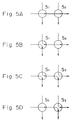
- FIGs 5A through 5D show methods for connecting switches. Each illustrates a different method for connecting two [2] switches S1 and S2. A circle indicating that a switch connects a highway in an arrow direction but does not connect a highway not passing through therein.
- the switches in connection modules M1 and M2 shown in Figures 4A and 4B are switched to be pursuant to any of the switching methods shown in Figures 5A through 5D. Switches shown in Figures 4A and 4B are aligned, such that their last suffix letters correspond to the switch numbers shown in Figures 5A through 5D.
- the connecting method shown in Figure 5C is not used.
- Figure 6 shows an exemplary configuration of a switch.
- S A and S B are selectors.
- the selector S A and S B can generate outputs OA and OB by arbitrarily switching inputs IA and IB.
- selectors S A and S B receives an input IA and the other one of them receives an input IB and selector S A supplies an output OA to one of the horizontal highways 1 and selector S B supplies an output OB to one of the vertical highways 2.
- the selectors S A and S B receive a control signal supplied from the setting circuit 9, which sets the connections shown in Figures 5A through 5D.
- a switch S1 shown in Figure 5D has its selector S A select input IA and supply the same as output OA to the corresponding one of the horizontal highways 1, whereas it has its selector S B select no input and supply nothing as output OB to the corresponding one of the vertical highways 2.
- a switch S2 shown in Figure 5D has its selector S A select input IB and supply the same as output OA to the corresponding one of the horizontal highways 1, whereas it has its selector S B select input IA and supply the same as output OB to the corresponding one of the vertical highways 2.
- the switch shown in Figure 6 may perform a switching by software based on office data e.g. according to an externally supplied control signal from the setting circuit 9 or may be a semi-fixed switch.
- Figure 7 shows another embodiment of this invention. It shows a method for connecting highways of 4x4 SRMs in four [4] rows of connection modules. Parts shown in Figure 7 that are the same as those shown in Figures 4A and 4B have the same numbers.
- M1 and M2 are connection modules. S91, S92, S101, S102, S111, S112, S121, S122, switches S131, S132, S141, S142, S151, S152, S161 and S162 are switches.
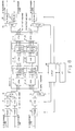
- Figure 8 is a block diagram of a third embodiment of this invention.
- Trunks 12 accommodate respective subscriber lines 11 on the input side, and connect them with VCCs (Virtual Channel Converters) 15.
- VCCs Virtual Channel Converters
- the VCCs 15 Based on call control information supplied via a CPIF (control device interface) 22 from a CC (central controller) 23 of an exchange, the VCCs 15 replace the original VCIs (Virtual Channel Identifiers), indicating the current output node (ATM exchange) as the destination of cells, attached to the headers of cells inputted from respective input highways 14 with the new VCIs indicating the next output nodes, and attach to the head ends of cells in a form of tags data over which paths in an MSSR 16 those cells are switched for their destined outputs to output highways 18.
- VCIs Virtual Channel Converters
- the MSSR 16 which is a virtual communications part, receives outputs from the VCCs 15 multiplexed by MUXs (multiplexers) 13 over to input highways 14.
- the MSSR 16 comprises a plurality of SRMs 17 (17-11 through 17-25, which are the same as those shown in Figure 1) and connection modules 10 (10-12 through 10-24).
- Figure 8 shows an example of a 2x5 multiple stage configuration in which SRMs 17-11 and 17-21 form a first stage, connection modules 10-12 and 10-22 form a second stage, SRMs 17-13 and 17-23 form the third stage, connection modules 10-14 and 10-24 form a fourth stage and SRMs 17-15 and 17-25 form the fifth stage.
- the MSSR 16 outputs cells via the output highways 18 respectively to DMUXs (demultiplexers) 19 to be demultiplexed for outputs via corresponding trunks 20 for outputs to subscriber lines 21 on the output side.
- DMUXs demultiplexers
- Figure 6 shows the configuration of a cell communications path part only in one [1] direction, it goes without saying that the communications path part for the cells in the reverse direction is configured in a same manner.
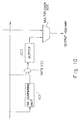
- FIG 9 is a block diagram of one of the VCCs 15 shown in Figure 8.
- a VPI/VCI detecting unit 501 detects a VPI (virtual path identifier) and a VCI (Virtual channel identifier) and a VPI (Virtual Path Identifier) in the header of a cell inputted from the corresponding one of the trunks 12.
- a table readout controlling unit 502 reads corresponding tag data from a VPI/VCI table 503 by using the detected VPI and VCI as an address.
- a multiplexing unit 505 adds to the head end of a cell delayed by a delaying unit 504 tag data read from a table readout controlling unit 502 for its output.
- the conversion table for obtaining tag data from the VPI and VCI stored in the VPI/VCI table 503 is set by the CC 23 via the CPIF 22.
- a test cell generating unit (TCG) 506 generates a test cell for testing the MSSR 16.
- the multiplexing unit 505 multiplexes the test cell over to a free time slots on input highways 14.
- Figure 10 is a block diagram for any of crossing point B11 through B44.
- a tag comparing unit 601 detects a tag attached to the head end of a cell inputted from an input line 401 and determines whether or not to switch the cell at the home crossing point. If it determines positively, it turns on a gate 602, and allow a buffer 603 to receive a cell inputted from an input highway after tag data. Then, a multiplexing unit 604 multiplexes a cell stored in a buffer 603 over to a free time slot on an output highway.
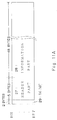
- Figure 11A shows a data structure of an ATM cell handled by an ATM exchange
- Figure 11B shows a data structure of a tag part.
- An ATM cell usually has the following data structure. As shown in Figure 11A, a cell has forty-eight [48] bytes of an information part 28 for storing payload communications data, and five [5] bytes of a header part 27 for storing destination data, e.g. VCI and VPI on the destination data for a receiving side subscriber, a CRC (cyclical redundancy check) code for correcting an error, data on a payload type of a cell, a cell loss priority data indicating the priority of discarding a cell in case of a congestion.
- destination data e.g. VCI and VPI on the destination data for a receiving side subscriber
- CRC cyclical redundancy check
- An ATM cell additionally comprises within an MSSR 16 two [2] bytes of a tag part 29 for storing data indicating over which path in the MSSR 16 a cell is switched for their outputs to destined ones of the output highways 18.
- Each of the VCCs 15 shown in Figure 8 attaches the tag part 29 to a received ATM cell.
- FIG 11B shows the configuration of the tag part 29.
- the tag part 29 has three [3] stages of tag data 30 e.g. each of four [4] bits for having switches in the three [3] stages of the SRMs 17 in the MSSR 16. It also comprises four [4] bits of demultiplexer tag 31, which determines over which one of the subscriber lines 21 a cell inputted via one of the output highways 18 is to be outputted from a destined one of the DMUXs 19.
- an ATM exchange transfers a cell from one of the subscriber lines 11 on the input side to one of the subscriber lines on the output side.
- trunks 12' and 20', VCCs 15', MUX 13' and DMUX 19' are provided additionally in the number additions to the subscriber lines 11 and 21, as well as additional rows of SRMs 17 (17-31, 17-33 and 17-35 in this case) and connection modules 10 (10-32 and 10-34 in this case) in the MSSR 16.
- Figure 12 is a block diagram showing additional subscriber lines 11 and 21 to the third embodiment of this invention.
- An increase in the number of subscriber lines 11 and 21 causes a mere addition of trunks 12' and 20', a VCC 15' a multiplexer 13' and a demultiplexer 19'.
- connection modules 10-12 through 10-24 are reset, and connection modules 10-32 and 10-34 are set, e.g. by changing the memory content of the CC 23.
- the CC 23 based on its memory content, controls the selectors S A and S B in each of the connection modules 10-12 through 10-34.
- this invention enables a use of interstage connection lines and connection modules of the same configuration to allow extra SRMs to be added to the existing SRMs, and an MSSR making desired highway connections to be structured simply by setting the switching method for switches in connection modules and the connecting method for connecting the connection lines between the SRMs in the first row and the SRMs in the last row. Therefore, this invention can minimize an effect on existing devices, when SRMs are added to an MSSR.
Landscapes
- Engineering & Computer Science (AREA)
- Computer Networks & Wireless Communication (AREA)
- Signal Processing (AREA)
- Physics & Mathematics (AREA)
- Mathematical Physics (AREA)
- Data Exchanges In Wide-Area Networks (AREA)
- Use Of Switch Circuits For Exchanges And Methods Of Control Of Multiplex Exchanges (AREA)
- Medicines That Contain Protein Lipid Enzymes And Other Medicines (AREA)
Applications Claiming Priority (2)
| Application Number | Priority Date | Filing Date | Title |
|---|---|---|---|
| JP227747/91 | 1991-09-09 | ||
| JP22774791A JP3023721B2 (ja) | 1991-09-09 | 1991-09-09 | Srm間ハイウエイ接続方法および装置 |
Publications (1)
| Publication Number | Publication Date |
|---|---|
| EP0534232A1 true EP0534232A1 (de) | 1993-03-31 |
Family
ID=16865740
Family Applications (1)
| Application Number | Title | Priority Date | Filing Date |
|---|---|---|---|
| EP19920115427 Withdrawn EP0534232A1 (de) | 1991-09-09 | 1992-09-09 | Einrichtung und Verfahren zur Verbindung der SRM-Zwischenleitungen |
Country Status (3)
| Country | Link |
|---|---|
| EP (1) | EP0534232A1 (de) |
| JP (1) | JP3023721B2 (de) |
| CA (1) | CA2077882A1 (de) |
Families Citing this family (2)
| Publication number | Priority date | Publication date | Assignee | Title |
|---|---|---|---|---|
| JPH08102749A (ja) * | 1994-08-02 | 1996-04-16 | Fujitsu Ltd | Atmスイッチ及びatmスイッチによるパス張り替え方法 |
| JPH08265328A (ja) * | 1995-03-20 | 1996-10-11 | Fujitsu Ltd | 多段接続スイッチおよびその増設方法 |
Citations (3)
| Publication number | Priority date | Publication date | Assignee | Title |
|---|---|---|---|---|
| EP0165499A1 (de) * | 1984-06-12 | 1985-12-27 | Siemens Aktiengesellschaft | Raummultiplexkoppelnetz |
| US4864558A (en) * | 1986-11-29 | 1989-09-05 | Nippon Telegraph And Telephone Corporation | Self-routing switch |
| US4993018A (en) * | 1987-02-06 | 1991-02-12 | Fujitsu Limited | Self-routing switching system with multiple link connections between incoming and outgoing lines |
-
1991
- 1991-09-09 JP JP22774791A patent/JP3023721B2/ja not_active Expired - Lifetime
-
1992
- 1992-09-09 EP EP19920115427 patent/EP0534232A1/de not_active Withdrawn
- 1992-09-09 CA CA 2077882 patent/CA2077882A1/en not_active Abandoned
Patent Citations (3)
| Publication number | Priority date | Publication date | Assignee | Title |
|---|---|---|---|---|
| EP0165499A1 (de) * | 1984-06-12 | 1985-12-27 | Siemens Aktiengesellschaft | Raummultiplexkoppelnetz |
| US4864558A (en) * | 1986-11-29 | 1989-09-05 | Nippon Telegraph And Telephone Corporation | Self-routing switch |
| US4993018A (en) * | 1987-02-06 | 1991-02-12 | Fujitsu Limited | Self-routing switching system with multiple link connections between incoming and outgoing lines |
Non-Patent Citations (1)
| Title |
|---|
| IEEE TRANSACTIONS ON COMPUTERS vol. 29, no. 10, October 1980, US pages 884 - 889 P. JANSEN ET AL * |
Also Published As
| Publication number | Publication date |
|---|---|
| JP3023721B2 (ja) | 2000-03-21 |
| JPH05130130A (ja) | 1993-05-25 |
| CA2077882A1 (en) | 1993-03-10 |
Similar Documents
| Publication | Publication Date | Title |
|---|---|---|
| US5313453A (en) | Apparatus for testing ATM channels | |
| Garcia-Haro et al. | ATM shared-memory switching architectures | |
| US5361255A (en) | Method and apparatus for a high speed asynchronous transfer mode switch | |
| US5485453A (en) | Method for handling redundant switching planes in packet switches and a packet switch for carrying out the method | |
| US5555243A (en) | Self routing exchange and exchange system | |
| US5239539A (en) | Controller for distributing loads among call processors | |
| KR100262682B1 (ko) | 멀티캐스트 atm교환기 및 그멀티캐스트 경합조정방법 | |
| US5168492A (en) | Rotating-access ATM-STM packet switch | |
| AU728583B2 (en) | Switching fabric | |
| AU631081B1 (en) | ATM cell error processing system | |
| EP0652685B1 (de) | Vermittlungseinrichtung nach einem asynchronen Transfermodus (ATM) | |
| EP0868054B1 (de) | Selbstarbitrierender Kreuzschienenschalter | |
| KR100250762B1 (ko) | 패킷 스위치의 링크를 그룹화하는 방법(a method of grouping links in a packet switch) | |
| US7088721B1 (en) | Method and apparatus for multipoint-to-point transmission in an ATM network | |
| US5390174A (en) | Method for handling information contained in a header portion of message cells transmitted in asynchronous transfer mode | |
| CN88100334A (zh) | 数字电路交换与分组交换网及其交换设施 | |
| EP0453129B1 (de) | Zeitmultiplex-Vermittlungssystem mit hoher Geschwindigkeit | |
| US6389014B1 (en) | ATM switching device and method capable of providing voice call service | |
| US6396811B1 (en) | Segmented performance monitoring of multi-stage ATM node | |
| US6507584B1 (en) | ATM switch | |
| EP1254532A2 (de) | Verfahren und einrichtung zum auswählen der besseren zelle redundanter ströme innerhalb einer zellen-orientierten umgebung | |
| EP0477553B1 (de) | Gerät zum Testen von Kommunikationskanälen | |
| US5191577A (en) | Switch stage number setting apparatus for MSSR channels | |
| US5325089A (en) | Two-stage, at least doubled ATM reversing switching network having (2n×2n) switching matrices | |
| EP0534232A1 (de) | Einrichtung und Verfahren zur Verbindung der SRM-Zwischenleitungen |
Legal Events
| Date | Code | Title | Description |
|---|---|---|---|
| PUAI | Public reference made under article 153(3) epc to a published international application that has entered the european phase |
Free format text: ORIGINAL CODE: 0009012 |
|
| AK | Designated contracting states |
Kind code of ref document: A1 Designated state(s): DE FR GB |
|
| 17P | Request for examination filed |
Effective date: 19930608 |
|
| 18W | Application withdrawn |
Withdrawal date: 19971217 |