EP0534096A2 - Method and device for examining impurities in containers - Google Patents
Method and device for examining impurities in containers Download PDFInfo
- Publication number
- EP0534096A2 EP0534096A2 EP92113169A EP92113169A EP0534096A2 EP 0534096 A2 EP0534096 A2 EP 0534096A2 EP 92113169 A EP92113169 A EP 92113169A EP 92113169 A EP92113169 A EP 92113169A EP 0534096 A2 EP0534096 A2 EP 0534096A2
- Authority
- EP
- European Patent Office
- Prior art keywords
- container
- cuvette
- gas
- containers
- measuring
- Prior art date
- Legal status (The legal status is an assumption and is not a legal conclusion. Google has not performed a legal analysis and makes no representation as to the accuracy of the status listed.)
- Granted
Links
Images


Classifications
-
- B—PERFORMING OPERATIONS; TRANSPORTING
- B08—CLEANING
- B08B—CLEANING IN GENERAL; PREVENTION OF FOULING IN GENERAL
- B08B9/00—Cleaning hollow articles by methods or apparatus specially adapted thereto
- B08B9/08—Cleaning containers, e.g. tanks
- B08B9/46—Inspecting cleaned containers for cleanliness
-
- G—PHYSICS
- G01—MEASURING; TESTING
- G01N—INVESTIGATING OR ANALYSING MATERIALS BY DETERMINING THEIR CHEMICAL OR PHYSICAL PROPERTIES
- G01N21/00—Investigating or analysing materials by the use of optical means, i.e. using sub-millimetre waves, infrared, visible or ultraviolet light
- G01N21/84—Systems specially adapted for particular applications
- G01N21/88—Investigating the presence of flaws or contamination
- G01N21/90—Investigating the presence of flaws or contamination in a container or its contents
- G01N21/9018—Dirt detection in containers
-
- G—PHYSICS
- G01—MEASURING; TESTING
- G01N—INVESTIGATING OR ANALYSING MATERIALS BY DETERMINING THEIR CHEMICAL OR PHYSICAL PROPERTIES
- G01N15/00—Investigating characteristics of particles; Investigating permeability, pore-volume, or surface-area of porous materials
- G01N2015/0007—Investigating dispersion of gas
- G01N2015/0011—Investigating dispersion of gas in liquids, e.g. bubbles
-
- G—PHYSICS
- G01—MEASURING; TESTING
- G01N—INVESTIGATING OR ANALYSING MATERIALS BY DETERMINING THEIR CHEMICAL OR PHYSICAL PROPERTIES
- G01N33/00—Investigating or analysing materials by specific methods not covered by groups G01N1/00 - G01N31/00
- G01N2033/0078—Investigating or analysing materials by specific methods not covered by groups G01N1/00 - G01N31/00 testing material properties on manufactured objects
- G01N2033/0081—Investigating or analysing materials by specific methods not covered by groups G01N1/00 - G01N31/00 testing material properties on manufactured objects containers; packages; bottles
Definitions
- the invention relates to a method for examining containers for foreign substances, a gas sample being taken from the container and being examined, and a device for examining containers for foreign substances with a line leading from an opening of the container to a measuring cell and with a gas source.
- a generic method and a generic device are known from EP-A-306 307.
- the bottles are transported on a rotary conveyor and are connected at their top to ionization chambers, into which samples in the bottles of "newly formed steam" are “drawn”. This is done using conventional pumps, venturi devices or blowers with or without vacuum accumulators or cylinders. Sampling takes place here by suction. This is disadvantageous and in particular is not sufficiently effective.
- the ionization also involves destruction of the foreign gases to be examined, so that there is a risk that certain molecules as such are destroyed and thus only the fractions but not the starting gases can be determined.
- the invention has for its object to provide a method and an apparatus that enable a quick and extremely reliable inspection of containers, in particular the bottles mentioned, whether there are or are interfering foreign substances in them.
- the above-mentioned object is achieved in a method of the type mentioned at the outset by taking the gas sample in such a way that a standard gas, such as air, is blown into the container in order to expel the gas in the container into a measuring cuvette and so that the previously the container and is examined photometrically in the measuring cuvette from this gas escaping due to the excess pressure caused.
- a device according to the invention is characterized in that the gas source is a standard gas pressure source and that a pressure line leading from the standard gas pressure source into the container is provided in addition to the removal line leading from the containers.
- the removal of gas in the bottles according to EP-A-306 307 into the surroundings has nothing to do with the sampling according to the invention by means of excess pressure.
- the photometric examination can be carried out, for example, according to DE-A-23 40 747 or WO 81/02633, which also show suitable detector devices.
- the standard gas is blown in via a lance moved into the container and the escaping air is fed to the measuring cell via a further lance, the standard gas in particular being blown centrally into the containers.
- the walls of the container are heated at least before the standard gas is blown in.
- the compressed air or a compressed gas expelling the air in the container is blown in centrally, so that the exiting air first brushes along the walls of the container and absorbs gas particles from it, which may have previously been expelled by the heating, and conduct the analysis can.
- a heating station is provided for the containers and that the heating station has IR radiators.
- a cuvette is provided for receiving the air pushed out of a container and the air pushed out of the container can be brought into the detector device in the cuvette.
- the cuvette is provided with heating devices.
- the pressure line has a lance which can be inserted centrally into a container and is characterized by a cap provided with an annular seal, on the periphery of which a discharge line for air pressed out of the container opens, which leads to a measuring cuvette.
- the measuring cell is provided with sealed viewing windows on the end face.
- the measuring cell has a high level of tightness since it is sealed on all sides, the inlet cylinder and, if applicable, outlets being able to be completely sealed by valves.
- the cuvette is provided with rinsing outlets in which a valve is arranged.
- the measuring cell is open on both end faces and its end faces are guided closely past stationary ring walls arranged on the inside and outside.
- the ring walls are closed except for individual outlets over the entire circumference.
- a preferred development provides that rinsing outlets and, if appropriate, inlets for the measuring cuvette are provided at suitable locations in the stationary ring walls, namely where the gas sampling device for removing the measuring gas from the containers to be examined is located (in the path of movement the detector device) and where the measuring cuvettes are cleaned again by neutral purging gas from the measuring gas (in the path of movement immediately behind the detector devices).
- the purging air can be supplied via the supply inlet rotating with the cuvette (through which the measuring gas is also fed to the measuring cuvette) or through an inlet provided in a ring wall on one end of the measuring cuvette, while an outlet is only on the opposite end is arranged.
- These configurations have the advantage that separate valves can be dispensed with, since the end faces are automatically adequately closed when they are moved from the inlet and outlet regions in the walls to the closed regions of the surrounding walls.
- the gap between the open end faces of the measuring cell and the surrounding closed ring walls is only a few hundredths of a millimeter thick. It has been found that the loss of sample gas is negligible.
- containers such as PET bottles, gas bottles or other containers, for gaseous foreign substances in them, such as hair tonic, oils or the like, but also decomposition gases from small animals introduced into the bottles or the like can be determined reliably and quickly.
- the invention can also be used for quality assurance in the production process. By working with excess pressure, from which the air in the bottle is expelled, a higher concentration of the foreign matter is brought into the measuring cuvette faster than would be the case with suction. This means that faster measurements and a higher throughput are required. It has been found that the particle concentration in the measuring cuvette can be significantly increased compared to suction by pressing out the air in the bottle. This is supported in that the container wall is heated before the suction.
- IR light for example in PET bottles
- IR light is 99% absorbed so that the bottle wall heats up. Due to the heating, due to the higher vapor pressure caused, gas molecules diffused into the wall are brought out of the latter and into the interior of the container. Due to the overpressure, they are expelled from the bottle and driven into the measuring cell.
- the device 1 according to the invention has a base frame 2.
- a feed path 3 for the containers 4 to be examined (FIG. 2), such as bottles, in particular PET bottles, is located on the base frame.
- a continuation path 6 is provided, which in the embodiment of the device according to the invention shown runs parallel to the feed path, but conveys the containers 4 out of the device according to the invention in the opposite direction.
- a transfer circular conveyor 7, 8 is assigned to each of the two tracks 3, 6.
- the actual examination device 9 is located between the two circular conveyors 7, 8, which also has a circular conveyor 11 and on the circumference of which a detector device 12 is arranged.
- receptacles 14 for the containers 4 are formed in the circumference of the circular conveyor 11, receptacles 14 for the containers 4 are formed. Above the receptacles 14, associated with each receptacle 14, there is in each case a cuvette 16 which runs through the detector devices 12, so that the gas in the cuvettes 16, which is removed from the containers 14 in a manner to be described below, contains foreign components can be examined.
- the cuvettes 16 can also be provided on the circular conveyor 11 also heating devices (not shown) in order to expel the gas in the cuvettes and to prepare them for further sampling from another container.
- the containers are fed via the feed path 3. Their walls are heated by the heating device 13, so that foreign gas components diffused into the walls, in particular foreign substances, such as solids, liquids or gases, which were previously in the bottles, exit into the bottle interior.
- the bottles are taken over by the transfer circular conveyor 7 and transferred to the circular conveyor 11. There, in the manner to be described below, a gas sample is taken, passed into the cuvette 16 assigned to the bottle and, as soon as it passes through the detector device 12, analyzed therein.
- the bottles are then transferred from the conveyor 11 to the transfer circular conveyor 8 and from there to the continuation track 6.
- the transfer circular conveyor 8 is provided with a control device controlled by the detector device 12, by means of which only harmless containers are transferred to the continuation track 6, while containers which have been identified as being of concern are ejected in a bottle discharge station 17.
- the containers 4 are held by holders 21, such as grippers or the like, on the circumference of the circular conveyor 11 in the receptacles 14.
- a gas extraction device 22 is located above the bottles or the receptacles 14. This has a compressed air line 23 leading into a cylinder 24.
- the cylinder 24 is located coaxially above the container 4 held by the holder 21.
- a compressed air lance 26, which can be inserted with its lower end into the container 4, projects tightly into the cylinder 24 in the opening region of the container 24. It is held by a movable block 27, which can be moved up and down on the circumference of the circular conveyor 11, the upper end of the lance 26 being inserted more or less deeply into the cylinder 24 and thereby moving out of the containers 4 or into them is driven in.
- a gas sampling lance 28 which opens at its lower end into a cap 29 which is provided on its lower end face with an annular seal 31 which, when the block 27 moves downward, firmly and sealingly on the upper edge of the container 4 is attachable.
- the lance 28 also projects into a cylinder 32 which opens into the cuvette 16 from its upper side.
- the cuvette 16 is provided with two outlets 33 which can be connected to an outlet line 36 via a valve 34.
- the compressed air line 23 can be connected to a compressed air source (not shown).
- the block 27, which carries the lances 26, 28, moves downward from an upper position and thereby leads the lower end of the Lance 26 into the openings of the container 4 until the seal 31 of the cap 29 firmly on the edge of the opening of the container 4 rests.
- the compressed air line 23, the cylinder 24 and the lance 26 pressurized gas, which may also be compressed air, from the compressed gas source (not shown) into the bottle 24. It is essential that the gas itself does not have any absorption bands in the region in which absorption bands from foreign gases or gases caused by foreign substances are expected.
- the air in the bottle with the gaseous impurity components which were previously operated by the heating device 13 from the wall of the bottle into the interior, is removed from the container via the Lance 28 removed and driven into the cuvette 16.
- neutral purging gas located in the cuvette and, if appropriate, also initially the first portion of the measurement gas funneled on the bottle are displaced from the cuvette 16 through the outlets 33 until the valve 34 is closed.
- the detector device 12 may have a plurality of light sources 41 and detectors 42.
- the cuvette 16 is provided with viewing windows 43, 44 on its end faces.
- the detector device 12 can have a plurality of units which are provided for different gas fractions and their absorption bands. If the cuvette has been brought out of the detector device by further movement of the circular conveyor 11, it can be flushed through air or a neutral gas - via the inlet cylinder 32 and the outlets 33 - and also heated to assist in expelling the gas removed from the container can be.
- the district sponsors work intermittently.
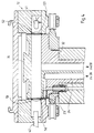
- FIGS. 3 and 4 show sections of a further preferred embodiment of the device according to the invention, FIG. 3 showing a section in the area of rinsing outlets 33 and FIG. 4 showing a section in the area of a detector device 12.
- the end faces 51, 52 of the measuring cell 16 are not provided with viewing windows, but rather are designed to be open.
- the end faces 51, 52 of the measuring cuvette 16 are at least over the circumference of the circular conveyor in the area in which the cuvette contains measuring gas, but preferably also in the area that follows the flushing station with neutral gas, by largely closed inner and outer walls 53, 54 covered.
- the gap between the end faces 51, 52 of the cuvette 16 and the stationary walls 53, 54 is in the range of a few hundredths of a millimeter, for example between 20 and 50 micrometers. It has already been found that the loss of measurement gas in the cuvette 16 through this column is negligible.
- the cuvette 16 is located in the area of the rinsing station for the cuvette 16 with openings 33, 33a in the walls 53, 54 surrounding it inside and outside.
- the opening 33 is a purge gas outlet 33, while the opening 33a is either can also be such an outlet or a purge air inlet.
- the rinsing air can be supplied via the sampling lance 28 rotating with the cuvette and the feed cylinder 32, the rinsing air then being supplied to these in a suitable manner (via a stationary slot opening).
- the design of the device in the area of the sampling station is essentially the same, but the pressure line 23 running around the cuvette 16 is guided past a corresponding stationary feed inlet area.
- FIG. 4 shows a section in the area of the detector device.
- the detector device also has a light source 41 and a detector 42 (if necessary, a plurality of detector devices 12 for different foreign gas components can be arranged one behind the other).
- An optical system with lenses 56, 57 is also provided, through which the light coming from the light source 41 is parallelized through the cuvette 16 or focused on the detector 42.
Abstract
Description
Die Erfindung betrifft ein Verfahren zum Untersuchen von Behältnissen auf Fremdstoffe, wobei aus dem Behältnis eine Gasprobe entnommen und untersucht wird, sowie eine Vorrichtung zur Untersuchung von Behältnissen auf Fremdstoffe mit einer von einer Öffnung des Behältnisses zu einer Meßküvette führenden Leitung und mit einer Gasquelle.The invention relates to a method for examining containers for foreign substances, a gas sample being taken from the container and being examined, and a device for examining containers for foreign substances with a line leading from an opening of the container to a measuring cell and with a gas source.
Bei Mehrwegbehältnissen, wie insbesondere Mehrweggetränkeflaschen, vor allem aus Kunststoffen, wie PET-Material, stellt sich das Problem, daß zwischen diesen Flaschen nicht Fremdstoffe, wie insbesondere fremde, schädliche Flüssigkeiten, gefunden haben dürfen. Flaschen, in denen sich solche Fremdstoffe befunden haben, müssen ausgeschieden werden und dürfen nicht wiederverwendet werden.In the case of reusable containers, such as in particular reusable beverage bottles, especially made of plastics, such as PET material, the problem arises that foreign substances, such as in particular foreign, harmful liquids, must not have found between these bottles. Bottles in which such foreign substances have been found must be excreted and must not be reused.
Aus der EP-A-306 307 ist ein gattungsgemäßes Verfahren und eine gattungsgemäße Vorrichtung bekannt. Die Flaschen werden auf einen Rotationsförderer befördert und sind an ihrer Oberseite mit Ionisationskammern verbunden, in die Proben in den Flaschen neu geformten Dampfes "gezogen" werden. Dies geschieht durch herkömmliche Pumpen, Venturi-Einrichtungen oder Gebläse mit oder ohne Vakuum-Akkumulatoren oder -zylinder. Die Probenentnahme erfolgt hier also durch Absaugen. Dies ist nachteilig und insbesondere nicht hinreichend wirksam. Auch beinhaltet die Ionisation eine Zerstörung der zu untersuchenden Fremdgase, so daß die Gefahr besteht, daß gewissen Moleküle als solche zerstört werden und damit nur die Bruchteile, nicht aber die Ausgangsgase festgestellt werden können.A generic method and a generic device are known from EP-A-306 307. The bottles are transported on a rotary conveyor and are connected at their top to ionization chambers, into which samples in the bottles of "newly formed steam" are "drawn". This is done using conventional pumps, venturi devices or blowers with or without vacuum accumulators or cylinders. Sampling takes place here by suction. This is disadvantageous and in particular is not sufficiently effective. The ionization also involves destruction of the foreign gases to be examined, so that there is a risk that certain molecules as such are destroyed and thus only the fractions but not the starting gases can be determined.
Damit nur Proben von aus den Wandungen des Behältnisses neu herausdiffundierter Fremdstoffe entnommen werden, ist nach der Druckschrift weiterhin vorgesehen, daß zeitlich und räumlich vor der Probennahme zunächst in den Flaschen befindliches Gas durch Überdruck in die freie Umgebung ausgetrieben wird.So that only samples of foreign substances newly diffused out of the walls of the container are taken, it is further provided according to the publication that time and place before the gas is taken, gas which is initially in the bottles is expelled into the free environment by overpressure.
Der Erfindung liegt die Aufgabe zugrunde, ein Verfahren und eine Vorrichtung zu schaffen, die eine schnelle und äußerst zuverlässige Überprüfung von Behältern, insbesondere den genannten Flaschen, darauf ermöglichen, ob sich in ihnen störende Fremdstoffe befunden haben oder befinden.The invention has for its object to provide a method and an apparatus that enable a quick and extremely reliable inspection of containers, in particular the bottles mentioned, whether there are or are interfering foreign substances in them.
Erfindungsgemäß wird die genannte Aufgabe bei einem Verfahren der eingangs genannten Art dadurch gelöst, daß die Gasprobe derart entnommen wird, daß in das Behältnis ein Normgas, wie Luft, eingeblasen wird, um in dem Behältnis befindliches Gas in eine Meßküvette auszutreiben und derart das vorher in dem Behältnis befindliche und aus diesem durch den bewirkten Überdruck austretende Gas in der Meßküvette photometrisch untersucht wird. Eine erfindungsgemäße Vorrichtung ist dadurch gekennzeichnet, daß die Gasquelle eine Normgas-Druckquelle ist und daß eine neben der aus den Behältnissen führenden Entnahmeleitung von der Normgas-Druckquelle in das Behältnis führende Druckleitung vorgesehen ist. Mit der erfindungsgemäßen Probeentnahme durch Überdruck hat das Entfernen von in den Flaschen befindlichem Gas nach der EP-A-306 307 in die Umgebung nichts zu tun. Die photometrische Untersuchung kann beispielsweise nach der DE-A-23 40 747 oder der WO 81/02633 erfolgen, die auch geeignete Detektoreinrichtungen zeigen.According to the invention, the above-mentioned object is achieved in a method of the type mentioned at the outset by taking the gas sample in such a way that a standard gas, such as air, is blown into the container in order to expel the gas in the container into a measuring cuvette and so that the previously the container and is examined photometrically in the measuring cuvette from this gas escaping due to the excess pressure caused. A device according to the invention is characterized in that the gas source is a standard gas pressure source and that a pressure line leading from the standard gas pressure source into the container is provided in addition to the removal line leading from the containers. The removal of gas in the bottles according to EP-A-306 307 into the surroundings has nothing to do with the sampling according to the invention by means of excess pressure. The photometric examination can be carried out, for example, according to DE-A-23 40 747 or WO 81/02633, which also show suitable detector devices.
In bevorzugter Weiterbildung kann vorgesehen sein, daß das Normgas über eine in das Behältnis hineinbewegte Lanze eingeblasen und die austretende Luft über eine weitere Lanze der Meßküvette zugeführt wird, wobei insbesondere das Normgas zentral in die Behältnisse eingeblasen wird. Eine weitere bevorzugte Ausgestaltung sieht vor, daß die Wandungen des Behältnisses zumindestens vor Einblasen des Normgases erwärmt werden. Hierdurch wird die die in dem Behälter befindliche Luft austreibende Druckluft oder ein Druckgas zentral eingeblasen, so daß die austretende Luft vorher an den Wandungen des Behälters entlangstreift und von diesem Gaspartikel von Fremdstoffen, die vorher gegebenenfalls durch die Erwärmung ausgetrieben wurden, aufnehmen und der Untersuchung zuführen kann.In a preferred development, it can be provided that the standard gas is blown in via a lance moved into the container and the escaping air is fed to the measuring cell via a further lance, the standard gas in particular being blown centrally into the containers. A further preferred embodiment provides that the walls of the container are heated at least before the standard gas is blown in. As a result, the compressed air or a compressed gas expelling the air in the container is blown in centrally, so that the exiting air first brushes along the walls of the container and absorbs gas particles from it, which may have previously been expelled by the heating, and conduct the analysis can.
Weiterbildungen der erfindungsgemäßen Vorrichtung sehen vor, daß eine Heizstation für die Behälter vorgesehen ist und daß die Heizstation IR-Strahler aufweist.Further developments of the device according to the invention provide that a heating station is provided for the containers and that the heating station has IR radiators.
Gemäß einer weiteren Ausgestaltung der Erfindung ist vorgesehen, daß eine Küvette zur Aufnahme der aus einem Behälter herausgedrückten Luft vorgesehen und die aus dem Behälter herausgedrückte Luft in der Küvette in die Detetektoreinrichtung bringbar ist. Darüber hinaus zeichnet sich eine Weiterbildung dadurch aus, daß die Küvette mit Heizeinrichtungen versehen ist. Weitere Ausgestaltungen sehen vor, daß die Druckleitung eine Lanze aufweist, die zentral in einen Behälter einführbar ist und gekennzeichnet ist durch eine mit einer Ringdichtung versehenen Kappe, an dessen Umfang eine Entnahmeleitung für aus dem Behälter herausgedrückte Luft mündet, die zu einer Meßküvette führt.According to a further embodiment of the invention, it is provided that a cuvette is provided for receiving the air pushed out of a container and the air pushed out of the container can be brought into the detector device in the cuvette. In addition, a further development is characterized in that the cuvette is provided with heating devices. Further refinements provide that the pressure line has a lance which can be inserted centrally into a container and is characterized by a cap provided with an annular seal, on the periphery of which a discharge line for air pressed out of the container opens, which leads to a measuring cuvette.
Gemäß einer Ausgestaltung ist vorgesehen, daß die Meßküvette stirnseitig mit dichten Sichtfenstern versehen ist. In diesem Falle weist die Meßküvette eine hoche Dichtigkeit auf, da sie allseitig abgedichtet ist, wobei der Einlaßzylinder und gegebenenfalls Auslässe durch Ventile vollständig abgedichtet werden können. Grundsätzlich und in diesem Falle ist weiterhin vorgesehen, daß die Küvette mit Spül-Auslässen versehen ist, in denen ein Ventil angeordnet ist.According to one embodiment, it is provided that the measuring cell is provided with sealed viewing windows on the end face. In this case, the measuring cell has a high level of tightness since it is sealed on all sides, the inlet cylinder and, if applicable, outlets being able to be completely sealed by valves. Basically and in this case it is further provided that the cuvette is provided with rinsing outlets in which a valve is arranged.
In einer bevorzugten alternativen Ausgestaltung kann aber vorgesehen sein, daß die Meßküvette an beiden Stirnseiten offen ist und ihre Stirnseiten dicht an innen- und außenseitig angeordneten stationären Ringwandungen vorbeigeführt werden. Die Ringwandungen sind dabei bis auf einzelne Auslässe über den gesamten Umfang geschlossen. Diese Ausgestaltung weist den Vorteil auf, daß keine Sichtfenster vorhanden sind, die verschmutzen können und daher wiederholt gereinigt werden müssen, was zu unerwünschten Standzeiten führen kann. Bei dieser Ausgestaltung sieht eine bevorzugte Weiterbildung vor, daß Spülaus- und gegebenenfalls -Einlässe für die Meßküvette an geeigneten Stellen in den stationären Ringwandungen vorgesehen sind, nämlich dort, wo sich die Gasentnahmeeinrichtung zur Entnahme des Meßgases aus den zu untersuchenden Behältern befindet (in Bewegungsweg vor der Detektoreinrichtung) und dort, wo die Meßküvetten durch neutrales Spülgas von dem Meßgas wieder gereinigt werden (im Bewegungsweg unmittelbar hinter den Detektoreinrichtungen).In a preferred alternative embodiment, however, it can be provided that the measuring cell is open on both end faces and its end faces are guided closely past stationary ring walls arranged on the inside and outside. The ring walls are closed except for individual outlets over the entire circumference. This configuration has the advantage that there are no viewing windows are present that can become dirty and therefore have to be cleaned repeatedly, which can lead to undesirable downtimes. In this embodiment, a preferred development provides that rinsing outlets and, if appropriate, inlets for the measuring cuvette are provided at suitable locations in the stationary ring walls, namely where the gas sampling device for removing the measuring gas from the containers to be examined is located (in the path of movement the detector device) and where the measuring cuvettes are cleaned again by neutral purging gas from the measuring gas (in the path of movement immediately behind the detector devices).
Die Spülluft kann dabei über den mit der Küvette umlaufenden Zuführeinlaß (durch den auch das Meßgas der Meßküvette zugeführt wird) zugeführt werden oder aber eben durch einen in einer Ringwandung stationär vorgesehenen Einlaß auf der einen Stirnseite der Meßküvette, während lediglich auf der gegenüberliegenden Stirnseite ein Auslaß angeordnet ist. Diese Ausgestaltungen weisen den Vorteil auf, daß separate Ventile entfallen können, da die Stirnseiten automatison hinreichend verschlossen werden, wenn sie aus den Ein- und Auslaßbereichen in den Wandungen zu den geschlossenen Bereichen der umgebenden Wandungen bewegt werden. Der Spalt zwischen den offenen Stirnseiten der Meßküvette und den umgebenden geschlossenen Ringwandungen weist lediglich eine Stärke von wenigen Hundertstel Millimetern auf. Es hat sich herausgestellt, daß der Verlust von Meßgas vernachlässigbar ist.The purging air can be supplied via the supply inlet rotating with the cuvette (through which the measuring gas is also fed to the measuring cuvette) or through an inlet provided in a ring wall on one end of the measuring cuvette, while an outlet is only on the opposite end is arranged. These configurations have the advantage that separate valves can be dispensed with, since the end faces are automatically adequately closed when they are moved from the inlet and outlet regions in the walls to the closed regions of the surrounding walls. The gap between the open end faces of the measuring cell and the surrounding closed ring walls is only a few hundredths of a millimeter thick. It has been found that the loss of sample gas is negligible.
Durch die Erfindung wird erreicht, daß Behälter, wie PET-Flaschen, Gasflaschen oder auch andere Behältnisse, auf in ihnen befindliche gasförmige Fremdstoffe, wie Haarwasser, Öle oder dergleichen, aber auch Verwesungsgase von in die Flaschen eingebrachten Kleintieren oder dergleichen zuverlässig und schnell festgestellt werden können. Darüber hinaus kann die Erfindung auch zur Qualitätssicherung im Produktionsprozeß eingesetzt werden. Durch das Arbeiten mit Überdruck, aus dem die in der Flasche befindliche Luft ausgetrieben wird, wird schneller eine höhere Konzentration des Fremdstoffes in die Meßküvette gebracht, als dies beim Absaugen der Fall wäre. Es sind damit schnellere Messungen und insgesamt ein höherer Durchsatz erforderlich. So hat man festgestellt, daß die Partikelkonzentration in der Meßküvette durch das Herausdrücken der in der Flasche befindlichen Luft gegenüber dem Absaugen deutlich erhöht werden kann. Dies wird dadurch unterstützt, daß die Behälterwandung vor den Absaugen erwärmt wird. Es hat sich gezeigt, daß IR-Licht, beispielsweise in PET-Flaschen, zu 99 % absorbiert wird, damit die Flaschenwandung erwärmt. Durch die Erwärmung werden aufgrund des bedingten höheren Dampfdrucks in die Wandung hineindiffundierte Gasmoleküle wieder aus diesen heraus in das Innere des Behältnisses gebracht. Durch den Überdruck werden sie aus der Flasche aus- und in die Meßküvette eingetrieben.It is achieved by the invention that containers, such as PET bottles, gas bottles or other containers, for gaseous foreign substances in them, such as hair tonic, oils or the like, but also decomposition gases from small animals introduced into the bottles or the like can be determined reliably and quickly. In addition, the invention can also be used for quality assurance in the production process. By working with excess pressure, from which the air in the bottle is expelled, a higher concentration of the foreign matter is brought into the measuring cuvette faster than would be the case with suction. This means that faster measurements and a higher throughput are required. It has been found that the particle concentration in the measuring cuvette can be significantly increased compared to suction by pressing out the air in the bottle. This is supported in that the container wall is heated before the suction. It has been shown that IR light, for example in PET bottles, is 99% absorbed so that the bottle wall heats up. Due to the heating, due to the higher vapor pressure caused, gas molecules diffused into the wall are brought out of the latter and into the interior of the container. Due to the overpressure, they are expelled from the bottle and driven into the measuring cell.
Weitere Vorteile und Merkmale der Erfindung ergeben sich aus den Ansprüchen und aus der nachfolgenden Beschreibung, der ein Ausführungsbeispiel der erfindungsgemäßen Vorrichtung zum Untersuchen von Behältnissen auf Fremdstoffe unter Bezugnahme auf die Zeichnung im einzelnen erläutert ist. Dabei zeigt:
Figur 1- eine schematische Gesamtdarstellung der bevorzugten Ausführungsform der erfindungsgemäßen Vorrichtung in Draufsicht;
- Figur 2
- eine Seitenansicht, teilweise geschnitten der wesentlichen erfinderischen Teile der erfindungsgemäßen Vorrichtung;
Figur 3- einen Schnitt durch eine weitere Ausgestaltung der erfindungsgemäßen Vorrichtung mit stirnseitig offener Meßküvette im Bereich von stationären Gasauslässen; und
Figur 4- einen Schnitt durch die Ausgestaltung der
Figur 3 im Bereich einer Detektoreinrichtung.
- Figure 1
- a schematic overall view of the preferred embodiment of the device according to the invention in plan view;
- Figure 2
- a side view, partially in section of the essential inventive parts of the device according to the invention;
- Figure 3
- a section through a further embodiment of the device according to the invention with a measuring cuvette open at the end in the region of stationary gas outlets; and
- Figure 4
- a section through the configuration of Figure 3 in the region of a detector device.
Die erfindungsgemäße Vorrichtung 1 weist ein Grundgestell 2 auf. Auf dem Grundgestell befindet sich eine Zuführbahn 3 für die zu untersuchenden Behältnisse 4 (Figur 2), wie Flaschen, insbesondere PET-Flaschen. Weiterhin ist eine Fortführbahn 6 vorgesehen, die bei der dargestellten Ausführungsform der erfindungsgemäßen Vorrichtung parallel zur Zuführbahn verläuft, die Behältnisse 4 aber in Gegenrichtung aus der erfindungsgemäßen Vorrichtung herausfördert. In beiden Bahnen 3, 6 ist jeweils ein Übergabe-Kreisförderer 7, 8 zugeordnet. Zwischen den beiden Kreisförderern 7, 8 befindet sich die eigentliche Untersuchungseinrichtung 9, die ebenfalls einen Kreisförderer 11 aufweist und an deren Umfang eine Detektoreinrichtung 12 angeordnet ist. Beidseits der Zuführbahn 3 befindet sich eine Heizeinrichtung 13, beispielsweise in Form von Infrarotstrahlern, die sich über die Höhe der Behältnisse 4 erstrecken.The
Im Umfang des Kreisförderers 11 sind Aufnahmen 14 für die Behältnisse 4 ausgebildet. Oberhalb der Aufnahmen 14 befinden sich, jeder Aufnahme 14 zugeordnet, jeweils eine Küvette 16, die durch die Detektoreinrichtungen 12 laufen, so daß dort das in den Küvetten 16 befindliche Gas, welches in noch zu beschreibender Weise aus den Behältnissen 14 entnommen wird, auf Fremdbestandteile untersucht werden kann. Den Küvetten 16 können weiter am Kreisförderer 11 ebenfalls Heizeinrichtungen vorgesehen sein (nicht dargestellt), um in den Küvetten befindliches Gas auszutreiben und diese für eine weitere Probennahme aus einen anderen Behältnis vorzubereiten.In the circumference of the
Die Behältnisse werden über die Zuführbahn 3 zugeführt. Ihre Wandungen werden durch die Heizeinrichtung 13 erwärmt, so daß in die Wandungen diffundierte Fremdgasanteile, insbesondere von Fremdstoffen, wie Festkörpern, Flüssigkeiten oder auch Gasen, die sich früher in den Flaschen befunden haben, wieder in das Flascheninnere austreten. Die Flaschen werden von Übergabe-Kreisförderer 7 übernommen und den Kreisförderer 11 übergeben. Dort wird in der weiter unten zu beschreibenden Weise eine Gasprobe genommen, in die der Flasche zugeordnete Küvette 16 geleitet und, sobald diese durch die Detektoreinrichtung 12 tritt, in dieser analysiert. Anschließend werden die Flaschen vom Förderer 11 auf den Übergabe-Kreisförderer 8 und von diesem der Fortführbahn 6 übergeben. Der Übergabe-Kreisförderer 8 ist mit einer durch die Detektoreinrichtung 12 gesteuerten Steuereinrichtung versehen, mittels derer nur unbedenkliche Behältnisse auf die Fortführbahn 6 übergeben werden, während als bedenklich festgestellte Behältnisse in einer Flaschenabwurfstation 17 ausgeworfen werden.The containers are fed via the
Die Behältnisse 4 werden durch Halterungen 21, wie Greifer oder dergleichen, am Umfang des Kreisförderers 11 in den Aufnahmen 14 gehalten. Oberhalb der Flaschen bzw. der Aufnahmen 14 befindet sich eine Gasentnahmeeinrichtung 22. Diese weist eine in einen Zylinder 24 führende Druckluftleitung 23 auf. Der Zylinder 24 befindet sich koaxial über dem durch die Halter 21 gehaltenen Behältnis 4. In den Zylinder 24 ragt, dicht einsitzend, im Öffnungsbereich des Behälters 24 eine Druckluftlanze 26, die mit ihrem unteren Ende in das Behältnis 4 einführbar ist. Sie wird durch einen verfahrbaren Block 27 gehalten, der am Umfang des Kreisförderer 11 auf- und abfahrbar ist, wobei das obere Ende der Lanze 26 mehr oder weniger tief in den Zylinder 24 eingefahren wird und dabei aus den Behältnissen 4 heraus- bzw. in diese hereingefahren wird. Mit den Block 27 ist weiterhin eine Gasentnahmelanze 28 verbunden, die an ihrem unteren Ende in eine Kappe 29 mündet, welche an ihrer unteren Stirnseite mit einer Ringdichtung 31 versehen ist, die bei Abwärtsbewegung des Blocks 27 fest und dichtend auf dem oberen Rand des Behältnisses 4 aufsetzbar ist. Die Lanze 28 ragt ebenfalls in einen Zylinder 32, der von seiner oberen Seite in die Küvette 16 mündet. Die Küvette 16 ist mit zwei Auslässen 33 versehen, die über ein Ventil 34 mit einer Auslaßleitung 36 in Verbindung bringbar sind. Die Druckluftleitung 23 ist an eine (nicht dargestellte) Druckluftquelle anschaltbar.The
Wenn die in der Heizstation 13 erwärmten Behältnisse 4 vom Übergabe-Heizförderer 7 zum Kreisförderer 11 übernommen wurden (Figur 1), verfährt der Block 27, der die Lanzen 26, 28 trägt, aus einer oberen Stellung nach unten und führt dabei das untere Ende der Lanze 26 in die Öffnungen des Behältnisses 4 ein, bis die Dichtung 31 der Kappe 29 fest auf dem Rand der Öffnung des Behältnisses 4 aufliegt. Anschließend wird von der Druckgasquelle (nicht dargestellt) die Druckluftleitung 23, der Zylinder 24 und die Lanze 26 unter Druck stehendes Gas, das gegebenenfalls auch Druckluft sein kann, in die Flasche 24 gedrückt. Wesentlich ist, daß das Gas in dem Bereich, in dem Absorptionsbanden von Fremdgasen bzw. durch Fremdstoffe bedingten Gase erwartet werden, selbst kein Absorptionsbanden aufweist. Durch die über die Lanze 26 in das Behältnis 4 eingedrückte Druckluft oder das eingedrückte Druckgas wird die in der Flasche befindliche Luft mit den gasförmigen Verunreinigungsanteilen, die vorher durch die Heizeinrichtung 13 aus der Wandung der Flasche in das Innere betrieben wurden, aus dem Behältnis über die Lanze 28 aus- und in die Küvette 16 getrieben. Dabei wird in der Küvette befindliches neutrales Spülgas und gegebenenfalls auch zunächst der erste Anteil des an der Flasche getrichterten Meßgases aus der Küvette 16 durch die Auslässe 33 verdrängt, bis das Ventil 34 geschlossen wird.When the
Gelangt die Küvette 16 nun in die Detektoreinrichtung 12, so wird in der Küvette 16 befindliche Gas durch die Detektoreinrichtung 12 untersucht. Die Detektoreinrichtung 12 weist gegebenenfalls mehrere Lichtquellen 41 und Detektoren 42 auf. Die Küvette 16 ist hierzu an ihren Stirnseiten mit Sichtfenstern 43, 44 versehen. Gegebenenfalls kann die Detektoreinrichtung 12 mehrere Einheiten aufweisen, die für verschiedene Gasanteile und deren Absorptionsbanden vorgesehen sind. Wenn durch Weiterbewegung des Kreisförderers 11 die Küvette aus der Detektoreinrichtung herausgebracht wurde, so kann sie durch Luft oder ein neutrales Gas - über den Einlaßzylinder 32 und die Auslässe 33 - gespült werden, wobei sie ebenfalls zur Unterstützung des Austreibens des aus dem Behältnis entnommenen Gases erwärmt werden kann. Die Kreisförderer arbeiten intermetierend. Im weiteren Bewegungsablauf wird der Block 27 angehoben, löst damit die Dichtung 31 von der Öffnung des Behältnisses 4 und zieht das untere Ende der Lanze 26 aus dem Behältnis 4, so daß dieses dann an den Übergabe-Kreisförderer 9 übergeben werden kann. Es wird von diesem dann entweder auf die Fortführbahn übergeben oder aber durch die Abwurfeinrichtung eliminiert.If the
Die Figuren 3 und 4 zeigen Schnitte einer weiteren bevorzugten Ausgestaltung der erfindungsgemäßen Vorrichtung, wobei die Figur 3 einen Schnitt im Bereich von Spülauslässen 33 und die Figur 4 einen Schnitt im Bereich einer Detektoreinrichtung 12 zeigt.FIGS. 3 and 4 show sections of a further preferred embodiment of the device according to the invention, FIG. 3 showing a section in the area of rinsing
Bei dieser Ausgestaltung sind die Stirnseiten 51, 52 der Meßküvette 16 nicht mit Sichtfenstern versehen, sondern vielmehr offen ausgebildet. Die Stirnseiten 51, 52 der Meßküvette 16 werden dabei zumindestens über den Umfang des Kreisförderers in den Bereich, in dem die Küvette Meßgas enthält, vorzugsweise aber auch in dem Bereich, der der Spülstation mit Neutralgas folgt, durch weitgehend geschlossene innere und äußere Wandungen 53, 54 abgedeckt. Der Spalt zwischen den Stirnseiten 51, 52 der Küvette 16 und den stationären Wandungen 53, 54 liegt dabei im Bereich von wenigen Hundertstel Millimeter, beispielsweise zwischen 20 und 50 Mikrometern. Es hat sich schon herausgestellt, daß der Verlust von in der Küvette 16 befindlichen Meßgas durch diese Spalte vernachlässigbar ist. Bei der Ausgestaltung der Figur 3 befindet sich die Küvette 16 im Bereich der Spülstation für die Küvette 16 mit Öffnungen 33, 33a in den sie innen und außen umgebenden Wandungen 53, 54. Die Öffnung 33 ist dabei ein Spülgasauslaß 33, während die Öffnung 33a entweder ebenfalls ein solcher Auslaß oder ein Spüllufteinlaß sein kann. Im ersteren Falle (wenn 33a auch ein Auslaß ist), so kann die Spülluft über die mit der Küvette umlaufende Probeentnahmelanze 28 und den Zuführzylinder 32 zugeführt werden, wobei die Spülluft diesen dann in geeigneter Weise (über eine stationäre Langlochöffnung) zugeführt wird.In this embodiment, the end faces 51, 52 of the measuring
Die Ausgestaltung der Vorrichtung im Bereich der Probeentnahmestation ist im wesentlichen die gleiche, wobei dort allerdings die mit der Küvette 16 umlaufende Drucklaufleitung 23 an einem entsprechenden stationären Zuführeinlaßbereich vorbeigeführt wird.The design of the device in the area of the sampling station is essentially the same, but the
Die Figur 4 zeigt einen Schnitt im Bereich der Detektoreinrichtung. Die Detektoreinrichtung weist ebenfalls wie bei der Ausgestaltung der Figur 2 eine Lichtquelle 41 und einen Detektor 42 auf (gegebenenfalls können mehrere Detektoreinrichtungen 12 für verschiedene Fremdgasanteile hintereinander angeordnet sein). Es ist weiterhin eine Optik mit Linsen 56, 57 vorgesehen, durch die das von der Lichtquelle 41 ausgehende Licht durch die Küvette 16 hindurch parallelisiert bzw. auf den Detektor 42 fokussiert wird.FIG. 4 shows a section in the area of the detector device. As in the embodiment in FIG. 2, the detector device also has a
Soweit einzelne Elemente bei der Erläuterung der Figuren 3 und 4 nicht besonders erwähnt wurden, so sind sie ebenso wie bei der Ausgestaltung der Figur 2 ausgebildet.Insofar as individual elements were not specifically mentioned in the explanation of FIGS. 3 and 4, they are designed in the same way as in the embodiment of FIG. 2.
Claims (17)
Applications Claiming Priority (2)
| Application Number | Priority Date | Filing Date | Title |
|---|---|---|---|
| DE4126885 | 1991-08-14 | ||
| DE4126885A DE4126885A1 (en) | 1991-08-14 | 1991-08-14 | METHOD AND DEVICE FOR EXAMINING CONTAINERS FOR FOREIGN MATERIALS |
Publications (3)
| Publication Number | Publication Date |
|---|---|
| EP0534096A2 true EP0534096A2 (en) | 1993-03-31 |
| EP0534096A3 EP0534096A3 (en) | 1994-08-24 |
| EP0534096B1 EP0534096B1 (en) | 1997-11-05 |
Family
ID=6438293
Family Applications (1)
| Application Number | Title | Priority Date | Filing Date |
|---|---|---|---|
| EP92113169A Expired - Lifetime EP0534096B1 (en) | 1991-08-14 | 1992-08-01 | Method and device for examining impurities in containers |
Country Status (2)
| Country | Link |
|---|---|
| EP (1) | EP0534096B1 (en) |
| DE (2) | DE4126885A1 (en) |
Cited By (7)
| Publication number | Priority date | Publication date | Assignee | Title |
|---|---|---|---|---|
| US5365771A (en) * | 1992-07-09 | 1994-11-22 | Elpatronic Ag | Process and apparatus for testing bottles for contamination |
| EP0643840A1 (en) * | 1992-06-01 | 1995-03-22 | The Coca-Cola Company | A method and system for sampling and determining the presence of compounds in containers |
| EP0672900A2 (en) * | 1994-03-17 | 1995-09-20 | Elpatronic Ag | Method for cleaning a bottle testing system |
| DE4427314A1 (en) * | 1994-08-02 | 1996-02-15 | Graessle Walter Gmbh | Gas analysis device for analysing gaseous content of container |
| US5703300A (en) * | 1995-06-08 | 1997-12-30 | Elpatronic Ag | Container inspection apparatus |
| DE102004034852A1 (en) * | 2004-07-19 | 2006-02-16 | Krieg, Gunther, Prof. Dipl.-Phys. Dr.-Ing. | Travelling sampling head for monitoring contamination, is synchronized to engage, inject gas, and withdraw samples from mouths of containers moving along a production line |
| JP2010509142A (en) * | 2006-11-13 | 2010-03-25 | カーハーエス・アクチエンゲゼルシヤフト | Method for inspecting bottles or such containers, and measuring equipment for inspection or inspection sections of bottles or such containers |
Families Citing this family (5)
| Publication number | Priority date | Publication date | Assignee | Title |
|---|---|---|---|---|
| DE10200349A1 (en) * | 2002-01-08 | 2003-07-17 | Gerhart Schroff | Method and arrangement for foreign gas detection in the beam path of optical imaging and / or beam guidance systems |
| DE202004008202U1 (en) * | 2004-05-18 | 2005-09-29 | Krones Ag | Extraction unit for sampling gases from e.g. returned bottles for analysis, contains blowing nozzle and suction channel embedded in plate with planar side facing vessel |
| DE202004020280U1 (en) * | 2004-12-30 | 2006-02-09 | Krones Ag | Device for removing gas samples from hollow vessels and feeding to analysis device used in drinks industry comprises blasting nozzles displaced in transport direction arranged in front of suction channel |
| DE102007062812A1 (en) * | 2007-12-21 | 2009-07-16 | Khs Ag | Apparatus for treating bottles or similar containers, in particular filling machine |
| DE102011083037A1 (en) * | 2011-09-20 | 2013-03-21 | Krones Aktiengesellschaft | Method and device for inspection of containers and preforms |
Citations (7)
| Publication number | Priority date | Publication date | Assignee | Title |
|---|---|---|---|---|
| US3266292A (en) * | 1964-06-08 | 1966-08-16 | Nat Distillers Chem Corp | Method for detecting volatile organic contaminants in reusable containers |
| US3321954A (en) * | 1966-07-20 | 1967-05-30 | Nat Distillers Chem Corp | Contaminant detection apparatus |
| DE3534756A1 (en) * | 1985-09-28 | 1987-04-02 | Seitz Enzinger Noll Masch | METHOD FOR DETECTING POLLUTED KEGS AND SYSTEM FOR IMPLEMENTING THE METHOD |
| US4791820A (en) * | 1987-07-31 | 1988-12-20 | Pharmacology & Toxicology Research Laboratory | Apparatus module for collection of volatiles from test sample |
| EP0306307A2 (en) * | 1987-09-02 | 1989-03-08 | The Coca-Cola Company | Plastic container inspection process |
| DE9114357U1 (en) * | 1991-11-18 | 1992-03-26 | Holstein Und Kappert Ag, 4600 Dortmund, De | |
| DE4038993A1 (en) * | 1990-12-06 | 1992-06-11 | Lehmann Martin | METHOD FOR SELECTION OF CONTAINERS AND MEASURING ARRANGEMENT FOR DETERMINING A DECISION SIZE FOR THIS |
Family Cites Families (5)
| Publication number | Priority date | Publication date | Assignee | Title |
|---|---|---|---|---|
| DE7531561U (en) * | 1975-10-04 | 1976-02-19 | Kronseder, Hermann, 8404 Woerth | DEVICE FOR CHECKING TRANSPARENT BEVERAGE BOTTLES FOR CLEANLINESS |
| DE3023211A1 (en) * | 1979-06-28 | 1981-01-22 | Ti Fords Ltd | METHOD AND DEVICE FOR DETERMINING AN AQUEOUS LIQUID IN BOTTLES AND CONTAINERS |
| JPS6041850U (en) * | 1983-08-30 | 1985-03-25 | 株式会社 堀場製作所 | gas analyzer |
| DE3908934A1 (en) * | 1989-03-18 | 1990-09-20 | Msi Elektronik Gmbh | Device for gas analysis |
| DE9002150U1 (en) * | 1990-02-23 | 1990-04-26 | Umweltschutz-Gasmesstechnik Teichert Gmbh, 8500 Nuernberg, De |
-
1991
- 1991-08-14 DE DE4126885A patent/DE4126885A1/en not_active Withdrawn
-
1992
- 1992-08-01 DE DE59209009T patent/DE59209009D1/en not_active Expired - Lifetime
- 1992-08-01 EP EP92113169A patent/EP0534096B1/en not_active Expired - Lifetime
Patent Citations (7)
| Publication number | Priority date | Publication date | Assignee | Title |
|---|---|---|---|---|
| US3266292A (en) * | 1964-06-08 | 1966-08-16 | Nat Distillers Chem Corp | Method for detecting volatile organic contaminants in reusable containers |
| US3321954A (en) * | 1966-07-20 | 1967-05-30 | Nat Distillers Chem Corp | Contaminant detection apparatus |
| DE3534756A1 (en) * | 1985-09-28 | 1987-04-02 | Seitz Enzinger Noll Masch | METHOD FOR DETECTING POLLUTED KEGS AND SYSTEM FOR IMPLEMENTING THE METHOD |
| US4791820A (en) * | 1987-07-31 | 1988-12-20 | Pharmacology & Toxicology Research Laboratory | Apparatus module for collection of volatiles from test sample |
| EP0306307A2 (en) * | 1987-09-02 | 1989-03-08 | The Coca-Cola Company | Plastic container inspection process |
| DE4038993A1 (en) * | 1990-12-06 | 1992-06-11 | Lehmann Martin | METHOD FOR SELECTION OF CONTAINERS AND MEASURING ARRANGEMENT FOR DETERMINING A DECISION SIZE FOR THIS |
| DE9114357U1 (en) * | 1991-11-18 | 1992-03-26 | Holstein Und Kappert Ag, 4600 Dortmund, De |
Cited By (13)
| Publication number | Priority date | Publication date | Assignee | Title |
|---|---|---|---|---|
| EP0643840A1 (en) * | 1992-06-01 | 1995-03-22 | The Coca-Cola Company | A method and system for sampling and determining the presence of compounds in containers |
| TR28242A (en) * | 1992-06-01 | 1996-03-28 | Coca Cola Co | A method and system for sampling and determining the presence of substances in containers. |
| EP0643840A4 (en) * | 1992-06-01 | 1996-05-01 | Coca Cola Co | A method and system for sampling and determining the presence of compounds in containers. |
| US5365771A (en) * | 1992-07-09 | 1994-11-22 | Elpatronic Ag | Process and apparatus for testing bottles for contamination |
| EP0810040A1 (en) * | 1994-03-17 | 1997-12-03 | Elpatronic Ag | Means for cleaning a container testing system |
| EP0672900A2 (en) * | 1994-03-17 | 1995-09-20 | Elpatronic Ag | Method for cleaning a bottle testing system |
| EP0672900A3 (en) * | 1994-03-17 | 1996-06-05 | Elpatronic Ag | Method for cleaning a bottle testing system. |
| US5613713A (en) * | 1994-03-17 | 1997-03-25 | Elpatronic Ag | Arrangement for cleaning a container testing apparatus |
| DE4427314A1 (en) * | 1994-08-02 | 1996-02-15 | Graessle Walter Gmbh | Gas analysis device for analysing gaseous content of container |
| US5703300A (en) * | 1995-06-08 | 1997-12-30 | Elpatronic Ag | Container inspection apparatus |
| DE102004034852A1 (en) * | 2004-07-19 | 2006-02-16 | Krieg, Gunther, Prof. Dipl.-Phys. Dr.-Ing. | Travelling sampling head for monitoring contamination, is synchronized to engage, inject gas, and withdraw samples from mouths of containers moving along a production line |
| DE102004034852B4 (en) * | 2004-07-19 | 2015-06-18 | Gunther Krieg | Method and apparatus for inspecting containers for foreign matter |
| JP2010509142A (en) * | 2006-11-13 | 2010-03-25 | カーハーエス・アクチエンゲゼルシヤフト | Method for inspecting bottles or such containers, and measuring equipment for inspection or inspection sections of bottles or such containers |
Also Published As
| Publication number | Publication date |
|---|---|
| EP0534096A3 (en) | 1994-08-24 |
| DE59209009D1 (en) | 1997-12-11 |
| DE4126885A1 (en) | 1993-02-18 |
| EP0534096B1 (en) | 1997-11-05 |
Similar Documents
| Publication | Publication Date | Title |
|---|---|---|
| EP1811289B1 (en) | Method and apparatus for the inspection of bottles or similar containers | |
| EP0534096B1 (en) | Method and device for examining impurities in containers | |
| EP0579952A1 (en) | Method and device for testing of bottles for contamination | |
| DE19727942A1 (en) | Machine and method for closing bottles with caps | |
| WO1997019766A1 (en) | Process and device for conveying containers past a device for inspecting the container bases | |
| EP2092291A1 (en) | Method for the inspection of bottles or similar containers, and measuring station for an inspection or control segment for bottles or similar containers | |
| EP2450696A1 (en) | Method and device for inspecting containers | |
| DE3028818C2 (en) | ||
| EP0579055A1 (en) | Method and device for mass-spectrometrical testing of bottles for contamination | |
| EP3853168B1 (en) | Drinks processing system and method for filling a drink into containers | |
| DE4427314C2 (en) | Device for examining containers for foreign gases | |
| EP0653964B1 (en) | Method and device for the inspection of containers on a conveyor | |
| EP0747690A1 (en) | Device for inspecting containers | |
| DE3115735A1 (en) | DEVICE FOR X-RAY TESTING OF A WHEEL BODY FOR MOTOR VEHICLES | |
| DE102004004755A1 (en) | Method and device for producing and filling containers | |
| EP2720036B1 (en) | Device for inspecting products | |
| EP0759330A2 (en) | Device for the establishment of a fluid connection between a fixed fluid coupling and a moving container | |
| EP3684696B1 (en) | Device for manufacturing and filling containers | |
| DE60226046T2 (en) | SAMPLE DETECTION DEVICE FOR AUTOMATIC ELEMENTARY ANALYSIS DEVICES | |
| EP3418709B1 (en) | Method and device for leak detection in pressure containers | |
| DE2813757C2 (en) | Device for sorting objects according to material | |
| EP0778064A2 (en) | Filter device and filtering process | |
| DE3311360C2 (en) | ||
| DE102005034574A1 (en) | Method and device for taking and analyzing samples | |
| DE4115580C1 (en) | Irradiation appts. for photochemical reactions - has rotation symmetrical reaction vessel through which flowable medium can pass |
Legal Events
| Date | Code | Title | Description |
|---|---|---|---|
| PUAI | Public reference made under article 153(3) epc to a published international application that has entered the european phase |
Free format text: ORIGINAL CODE: 0009012 |
|
| AK | Designated contracting states |
Kind code of ref document: A2 Designated state(s): BE CH DE FR IT LI SE |
|
| PUAL | Search report despatched |
Free format text: ORIGINAL CODE: 0009013 |
|
| AK | Designated contracting states |
Kind code of ref document: A3 Designated state(s): BE CH DE FR IT LI SE |
|
| 17P | Request for examination filed |
Effective date: 19950211 |
|
| 17Q | First examination report despatched |
Effective date: 19960522 |
|
| GRAG | Despatch of communication of intention to grant |
Free format text: ORIGINAL CODE: EPIDOS AGRA |
|
| GRAH | Despatch of communication of intention to grant a patent |
Free format text: ORIGINAL CODE: EPIDOS IGRA |
|
| GRAH | Despatch of communication of intention to grant a patent |
Free format text: ORIGINAL CODE: EPIDOS IGRA |
|
| GRAA | (expected) grant |
Free format text: ORIGINAL CODE: 0009210 |
|
| AK | Designated contracting states |
Kind code of ref document: B1 Designated state(s): BE CH DE FR IT LI SE |
|
| RAP2 | Party data changed (patent owner data changed or rights of a patent transferred) |
Owner name: KHS MASCHINEN- UND ANLAGENBAU AKTIENGESELLSCHAFT |
|
| RIN2 | Information on inventor provided after grant (corrected) |
Free format text: RUPP, MICHAEL |
|
| REG | Reference to a national code |
Ref country code: CH Ref legal event code: EP |
|
| REF | Corresponds to: |
Ref document number: 59209009 Country of ref document: DE Date of ref document: 19971211 |
|
| ITF | It: translation for a ep patent filed |
Owner name: BARZANO' E ZANARDO ROMA S.P.A. |
|
| PG25 | Lapsed in a contracting state [announced via postgrant information from national office to epo] |
Ref country code: SE Free format text: LAPSE BECAUSE OF FAILURE TO SUBMIT A TRANSLATION OF THE DESCRIPTION OR TO PAY THE FEE WITHIN THE PRESCRIBED TIME-LIMIT Effective date: 19980205 |
|
| ET | Fr: translation filed | ||
| PG25 | Lapsed in a contracting state [announced via postgrant information from national office to epo] |
Ref country code: BE Free format text: LAPSE BECAUSE OF NON-PAYMENT OF DUE FEES Effective date: 19980831 |
|
| PLBE | No opposition filed within time limit |
Free format text: ORIGINAL CODE: 0009261 |
|
| STAA | Information on the status of an ep patent application or granted ep patent |
Free format text: STATUS: NO OPPOSITION FILED WITHIN TIME LIMIT |
|
| 26N | No opposition filed | ||
| BERE | Be: lapsed |
Owner name: RUPP MICHAEL Effective date: 19980831 |
|
| PGFP | Annual fee paid to national office [announced via postgrant information from national office to epo] |
Ref country code: CH Payment date: 20020529 Year of fee payment: 11 |
|
| PGFP | Annual fee paid to national office [announced via postgrant information from national office to epo] |
Ref country code: FR Payment date: 20020614 Year of fee payment: 11 |
|
| PG25 | Lapsed in a contracting state [announced via postgrant information from national office to epo] |
Ref country code: CH Free format text: LAPSE BECAUSE OF NON-PAYMENT OF DUE FEES Effective date: 20030831 Ref country code: LI Free format text: LAPSE BECAUSE OF NON-PAYMENT OF DUE FEES Effective date: 20030831 |
|
| REG | Reference to a national code |
Ref country code: CH Ref legal event code: PL |
|
| PG25 | Lapsed in a contracting state [announced via postgrant information from national office to epo] |
Ref country code: FR Free format text: LAPSE BECAUSE OF NON-PAYMENT OF DUE FEES Effective date: 20040430 |
|
| REG | Reference to a national code |
Ref country code: FR Ref legal event code: ST |
|
| PGFP | Annual fee paid to national office [announced via postgrant information from national office to epo] |
Ref country code: DE Payment date: 20110823 Year of fee payment: 20 |
|
| PGFP | Annual fee paid to national office [announced via postgrant information from national office to epo] |
Ref country code: IT Payment date: 20110824 Year of fee payment: 20 |
|
| REG | Reference to a national code |
Ref country code: DE Ref legal event code: R071 Ref document number: 59209009 Country of ref document: DE |
|
| REG | Reference to a national code |
Ref country code: DE Ref legal event code: R071 Ref document number: 59209009 Country of ref document: DE |
|
| PG25 | Lapsed in a contracting state [announced via postgrant information from national office to epo] |
Ref country code: DE Free format text: LAPSE BECAUSE OF EXPIRATION OF PROTECTION Effective date: 20120802 |