EP0534082A1 - Pump system for delivering liquid or gaseous media - Google Patents
Pump system for delivering liquid or gaseous media Download PDFInfo
- Publication number
- EP0534082A1 EP0534082A1 EP92112525A EP92112525A EP0534082A1 EP 0534082 A1 EP0534082 A1 EP 0534082A1 EP 92112525 A EP92112525 A EP 92112525A EP 92112525 A EP92112525 A EP 92112525A EP 0534082 A1 EP0534082 A1 EP 0534082A1
- Authority
- EP
- European Patent Office
- Prior art keywords
- pump system
- pressure vessel
- recipient
- membrane
- liquid
- Prior art date
- Legal status (The legal status is an assumption and is not a legal conclusion. Google has not performed a legal analysis and makes no representation as to the accuracy of the status listed.)
- Withdrawn
Links
- 239000007788 liquid Substances 0.000 title claims abstract description 9
- 239000011888 foil Substances 0.000 claims abstract description 5
- 239000000463 material Substances 0.000 claims abstract description 3
- 239000012528 membrane Substances 0.000 claims description 6
- PEDCQBHIVMGVHV-UHFFFAOYSA-N Glycerine Chemical compound OCC(O)CO PEDCQBHIVMGVHV-UHFFFAOYSA-N 0.000 claims description 5
- 229920002981 polyvinylidene fluoride Polymers 0.000 claims description 5
- 239000002033 PVDF binder Substances 0.000 claims description 3
- 239000012799 electrically-conductive coating Substances 0.000 claims description 2
- 230000000737 periodic effect Effects 0.000 claims description 2
- 235000011187 glycerol Nutrition 0.000 claims 1
- 230000008602 contraction Effects 0.000 description 2
- 238000000576 coating method Methods 0.000 description 1
- 238000011161 development Methods 0.000 description 1
- 230000018109 developmental process Effects 0.000 description 1
- 230000000694 effects Effects 0.000 description 1
- 230000001939 inductive effect Effects 0.000 description 1
- 230000010287 polarization Effects 0.000 description 1
- 238000005086 pumping Methods 0.000 description 1
Images
Classifications
-
- F—MECHANICAL ENGINEERING; LIGHTING; HEATING; WEAPONS; BLASTING
- F04—POSITIVE - DISPLACEMENT MACHINES FOR LIQUIDS; PUMPS FOR LIQUIDS OR ELASTIC FLUIDS
- F04B—POSITIVE-DISPLACEMENT MACHINES FOR LIQUIDS; PUMPS
- F04B43/00—Machines, pumps, or pumping installations having flexible working members
- F04B43/02—Machines, pumps, or pumping installations having flexible working members having plate-like flexible members, e.g. diaphragms
- F04B43/04—Pumps having electric drive
- F04B43/043—Micropumps
- F04B43/046—Micropumps with piezoelectric drive
Definitions
- the invention relates to a pump system for conveying liquid or gaseous media according to the preamble of claim 1.
- the present invention is based on the object of demonstrating a pump system of the type mentioned at the outset, the pump frequencies of which extend into the kHz range and higher, have rapid controllability, are almost free of power loss and are hardly subject to wear.
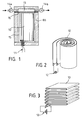
- the pump system shown there is based on an electrically conductive coating on both sides Film 10 made of a piezoelectric material - for example PVDF (polyvinylidene difluoride).
- This piezo film 10 is now folded (FIG. 3) or rolled in two layers (FIG. 2) in a pressure vessel DG filled with liquid 15 with low compressibility, which is closed with a membrane 16 towards the recipient 13.
- An inlet valve 14a and an outlet valve 14b are assigned to the recipient 13.
- An electrical control voltage 12 is applied to the piezo film 10 via electrical connections 11, which causes polarization and thus a change in the film thickness.
- the resulting change in pressure in the pressure vessel DG now moves the membrane 16, which in turn varies the volume of the recipient 13.
- a periodic change in voltage now produces a pumping effect in connection with the two valves 14a, 14b.
- this creates a pump system that operates at a very high frequency (kHz range and higher), has a quick controllability due to the low inertia of the drive, and since the piezoelectrics can in principle be controlled without power, only very low power losses occur because of ohmic and inductive There are no losses whatsoever. It is also essential that this pump system is almost wear-free.
- the transverse contraction must be prevented by the thickness and by the elastic properties of at least one of the electrically conductive coatings (electrodes), for example by an Al foil con bonded to the piezoelectric foil with approx Thickness of the PVDF piezoelectric film.
- the pressure vessel DG be replaced by a cylinder with a piston (not shown) complete, the diameter of the cylinder must be adapted to the desired piston stroke. This can be easily implemented by any specialist who has become familiar with the present pump system.
- the thickness dimensioning of the piezo film 10 should be 100 ⁇ m. As already explained above, the film 10 must be folded or rolled in two layers in the pressure vessel DG so that no contact can occur between the two contact surfaces.
Abstract
Description
Die Erfindung bezieht sich auf ein Pumpensystem zur Förderung von flüssigen oder gasförmigen Medien gemäß dem Gattungsbegriff des Anspruchs 1.The invention relates to a pump system for conveying liquid or gaseous media according to the preamble of claim 1.
Solche Pumpensysteme zählen in den verschiedensten Ausführungsformen und für die verschiedensten Zwecke zum Stand der Technik. Jedes dieser Systeme hat sich für den ihr zugeordneten Zweck bewährt, ist aber auch mit Nachteilen behaftet. Im einen Fall muß sehr niederfrequent gearbeitet werden, im anderen Fall ist die Trägheit des Antriebs zu groß oder im dritten Fall sind die Verlustleistungen zu hoch usw.Pump systems of this type are state of the art in a wide variety of embodiments and for a wide variety of purposes. Each of these systems has proven itself for the purpose assigned to it, but also has disadvantages. In one case you have to work very low frequency, in the other case the inertia of the drive is too great or in the third case the power losses are too high etc.
Der vorliegenden Erfindung liegt die Aufgabe zugrunde, ein Pumpensystem der eingangs genannten Art aufzuzeigen, dessen Pumpfrequenzen bis in den kHz-Bereich und höher reichen, eine schnelle Regelbarkeit aufweisen, nahezu verlustleistungsfrei sind und kaum einem Verschleiß unterliegen.The present invention is based on the object of demonstrating a pump system of the type mentioned at the outset, the pump frequencies of which extend into the kHz range and higher, have rapid controllability, are almost free of power loss and are hardly subject to wear.
Diese Aufgabenkombination wird durch die im Anspruch 1 aufgezeigten Maßnahmen in überraschend einfacher zuverlässiger Weise gelöst. In den Unteransprüchen sind Weiterbildungen und Ausgestaltungen angegeben und in der nachfolgenden Beschreibung werden Ausführungsbeispiele erläutert. Die Figuren der Zeichnung ergänzen diese Erläuterungen. Es zeigen:
- Fig. 1
- einen Querschnitt durch ein Ausführungsbeispiel in schematischer Darstellung,
- Fig. 2
- eine perspektivische Skizze für ein Ausführungsbeispiel mit gerollter Piezofolie in schematischer Darstellung,
- Fig. 3
- eine perspektivische Skizze für ein Ausführungsbeispiel mit gefalteter Piezofolie in schematischer Darstellung.
- Fig. 1
- 3 shows a cross section through an exemplary embodiment in a schematic illustration,
- Fig. 2
- 1 shows a perspective sketch for an exemplary embodiment with rolled piezo film in a schematic illustration,
- Fig. 3
- a perspective sketch of an embodiment with folded piezo film in a schematic representation.
Wie aus der Figur 1 der Zeichnung hervorgeht, basiert das dort dargestellte Pumpensystem auf einer beidseitig elektrisch leitend beschichteten Folie 10 aus einem piezoelektrischen Material - beispielsweise PVDF (Polyvinylidendifluorid). Diese Piezofolie 10 befindet sich nun gefaltet (Fig. 3) oder doppellagig gerollt (Fig. 2) in einem mit Flüssigkeit 15 mit geringer Kompressibilität gefüllten Druckgefäß DG, welches mit einer Membran 16 zum Rezipienten 13 hin abgeschlossen ist. Dem Rezipienten 13 sind ein Einlaßventil 14a und ein Auslaßventil 14b zugeordnet. Über elektrische Anschlüsse 11 wird an die Piezofolie 10 eine elektrische Steuerspannung 12 angelegt, die eine Polarisation und damit eine Änderung der Foliendicke bewirkt. Der hierdurch veränderte Druck im Druckgefäß DG bewegt nun die Membran 16, die ihrerseits das Volumen des Rezipienten 13 variiert.As can be seen from FIG. 1 of the drawing, the pump system shown there is based on an electrically conductive coating on both
Durch periodische Spannungsänderung wird nun in Verbindung mit den beiden Ventilen 14a, 14b eine Pumpwirkung erzielt. Damit ist aber nun ein Pumpensystem geschaffen, das sehr hochfrequent arbeitet (kHz-Bereich und höher), aufgrund der geringen Trägheit des Antriebes eine schnelle Regelbarkeit aufweist und da die Piezoelektrika im Prinzip leistungsfrei steuerbar sind, nur sehr geringe Verlustleistungen auftreten, weil ohmsche und induktive Verluste völlig entfallen. Weiterhin ist noch wesentlich, daß dieses Pumpensystem nahezu verschleißfrei ist.A periodic change in voltage now produces a pumping effect in connection with the two
Die Spannungsänderung und damit die Dickenänderung haben so schnell zu erfolgen, daß aufgrund der Massenträgheit der Folie und der Flüssigkeit (bei der gefalteten Folie) die Querkontraktion der Dickenänderung nicht folgen kann. Daraus resultiert die Volumenänderung der Folie.The change in tension and thus the change in thickness must take place so quickly that, due to the inertia of the film and the liquid (in the case of the folded film), the transverse contraction cannot follow the change in thickness. This results in the change in volume of the film.
Für den quasistatischen bzw. langsam veränderlichen Betrieb muß die Querkontraktion durch die Dicke und durch die elastischen Eigenschaften mindestens einer der elektrisch leitenden Beschichtungen (Elektroden) verhindert werden, beispielsweise durch eine, mit der piezoelektrischen Folie verklebten Al-Folie con ca. 1/10 der Dicke der piezoelektrischen Folie aus PVDF.For quasi-static or slowly changing operation, the transverse contraction must be prevented by the thickness and by the elastic properties of at least one of the electrically conductive coatings (electrodes), for example by an Al foil con bonded to the piezoelectric foil with approx Thickness of the PVDF piezoelectric film.
In einem weiteren Ausführungsbeispiel wird vorgeschlagen, anstelle einer Membran 13 das Druckgefäß DG durch einen Zylinder mit Kolben (nicht gezeichnet) abzuschließen, wobei der Durchmesser des Zylinders dem gewünschten Kolbenhub angepaßt werden muß. Dies ist für jeden Fachmann, der das vorliegende Pumpensystem kennengelernt hat, problemlos zu realisieren.In a further exemplary embodiment it is proposed that the pressure vessel DG be replaced by a cylinder with a piston (not shown) complete, the diameter of the cylinder must be adapted to the desired piston stroke. This can be easily implemented by any specialist who has become familiar with the present pump system.
Nachstehend soll rechnerisch ein Ausführungsbeispiel aufgezeigt werden. Hierbei wird ein zylindrisches Druckgefäß DG mit einem Durchmesser D = 30 mm, einer Höhe H = 50mm und damit mit einem Volumen V = 35 cm³ zugrunde gelegt. Die Dicken-Dimensionierung der Piezofolie 10 soll 100 µm sein. Wie vorstehend bereits ausgeführt, muß die Folie 10 so gefaltet oder doppellagig gerollt im Druckgefäß DG untergebracht werden, daß keine Kontaktierung der beiden Kontaktflächen auftreten kann.An exemplary embodiment is to be arithmetically shown below. This is based on a cylindrical pressure vessel DG with a diameter D = 30 mm, a height H = 50 mm and thus with a volume V = 35 cm³. The thickness dimensioning of the
Die Folienfläche, die maximal in dem Volumen V des Druckgefäßes DG untergebracht wird, ist AF = 3.500 cm². Unter Zugrundelegung eines Füllfaktors Ff = 0,6 wird AFeff = 2.000 cm².The maximum film area that is accommodated in the volume V of the pressure vessel DG is A F = 3,500 cm². Based on a fill factor F f = 0.6, A Feff = 2,000 cm².
Die Änderung der Dicke D der Piezofolie 10 bei einer elektrischen Spannung von 1.000 V beträgt 1 Promille: ΔD = 0,1 µm. Daraus ergibt sich unter der Voraussetzung, daß die Änderung der Dicke D nicht durch gegenläufige Änderung von Länge oder Breite der Folie 10 kompensiert werden kann:
![]()
Das Druckgefäß 10 ist mit einer inkompressiblen Flüssigkeit - beispielsweise Glyzerin mit K = 4.7 x 10³ MPa - gefüllt.The change in the thickness D of the
![]()
The
Die Druckänderung durch Volumenänderung errechnet sich aus:
![]()
dies entspricht ungefähr 27 bar.The change in pressure due to volume change is calculated from:
![]()
this corresponds to approximately 27 bar.
Wird nun nicht eine Membran sondern ein Zylinder mit Kolben an das Druckgefäß 10 angeschlossen, so wird ein Durchmesser von DK = 2mm und eine Fläche von AK = 3mm² angenommen. Die Durchrechnung dieses Ausführungsbeispiels ergibt, daß der Kolben mit einer Kraft von 8,1 N und einem Hub von 6 mm bewegt wird.If not a membrane but a cylinder with a piston is connected to the
Claims (5)
Applications Claiming Priority (2)
| Application Number | Priority Date | Filing Date | Title |
|---|---|---|---|
| DE4127860A DE4127860A1 (en) | 1991-08-22 | 1991-08-22 | PUMP SYSTEM FOR CONVEYING LIQUID OR GASEOUS MEDIA |
| DE4127860 | 1991-08-22 |
Publications (1)
| Publication Number | Publication Date |
|---|---|
| EP0534082A1 true EP0534082A1 (en) | 1993-03-31 |
Family
ID=6438886
Family Applications (1)
| Application Number | Title | Priority Date | Filing Date |
|---|---|---|---|
| EP92112525A Withdrawn EP0534082A1 (en) | 1991-08-22 | 1992-07-22 | Pump system for delivering liquid or gaseous media |
Country Status (2)
| Country | Link |
|---|---|
| EP (1) | EP0534082A1 (en) |
| DE (1) | DE4127860A1 (en) |
Cited By (1)
| Publication number | Priority date | Publication date | Assignee | Title |
|---|---|---|---|---|
| EP1323925A2 (en) * | 2001-12-25 | 2003-07-02 | Matsushita Electric Works, Ltd. | Electroactive polymer actuator and diaphragm pump using the same |
Families Citing this family (3)
| Publication number | Priority date | Publication date | Assignee | Title |
|---|---|---|---|---|
| DE4333871C2 (en) * | 1993-10-05 | 1997-02-20 | Daimler Benz Aerospace Ag | Electro-hydraulic actuator |
| DE102009045396A1 (en) * | 2009-10-06 | 2011-04-07 | Fev Motorentechnik Gmbh | Test-stand for testing fatigue strength e.g. transient fatigue, of cylindrical body of motor vehicle, has pressure generating unit and fixture including piezo-actuator and heating element, where load is applied on test objects |
| CN113994585A (en) * | 2019-06-18 | 2022-01-28 | Strawb股份有限公司 | Electrostatic actuator |
Citations (4)
| Publication number | Priority date | Publication date | Assignee | Title |
|---|---|---|---|---|
| DE3037380A1 (en) * | 1980-10-03 | 1982-05-13 | Carl Schenck Ag, 6100 Darmstadt | HYDRAULIC PRINTER GENERATOR AND / OR PRESSURE SUPPLY ARRANGEMENT |
| US4330730A (en) * | 1980-03-27 | 1982-05-18 | Eastman Kodak Company | Wound piezoelectric polymer flexure devices |
| DE3415421A1 (en) * | 1983-04-25 | 1984-10-31 | Ricoh Co., Ltd., Tokio/Tokyo | PUMP FOR COMPRESSING A LIQUID |
| FR2645349A1 (en) * | 1989-03-29 | 1990-10-05 | Pennwalt Corp | LAMINATED PIEZOELECTRIC STRUCTURE AND METHOD FOR ITS FORMATION |
Family Cites Families (2)
| Publication number | Priority date | Publication date | Assignee | Title |
|---|---|---|---|---|
| US3598506A (en) * | 1969-04-23 | 1971-08-10 | Physics Int Co | Electrostrictive actuator |
| DE3342844A1 (en) * | 1983-11-26 | 1985-06-05 | Philips Patentverwaltung Gmbh, 2000 Hamburg | MICROPLANAR INK JET PRINT HEAD |
-
1991
- 1991-08-22 DE DE4127860A patent/DE4127860A1/en not_active Ceased
-
1992
- 1992-07-22 EP EP92112525A patent/EP0534082A1/en not_active Withdrawn
Patent Citations (4)
| Publication number | Priority date | Publication date | Assignee | Title |
|---|---|---|---|---|
| US4330730A (en) * | 1980-03-27 | 1982-05-18 | Eastman Kodak Company | Wound piezoelectric polymer flexure devices |
| DE3037380A1 (en) * | 1980-10-03 | 1982-05-13 | Carl Schenck Ag, 6100 Darmstadt | HYDRAULIC PRINTER GENERATOR AND / OR PRESSURE SUPPLY ARRANGEMENT |
| DE3415421A1 (en) * | 1983-04-25 | 1984-10-31 | Ricoh Co., Ltd., Tokio/Tokyo | PUMP FOR COMPRESSING A LIQUID |
| FR2645349A1 (en) * | 1989-03-29 | 1990-10-05 | Pennwalt Corp | LAMINATED PIEZOELECTRIC STRUCTURE AND METHOD FOR ITS FORMATION |
Non-Patent Citations (2)
| Title |
|---|
| RESEARCH DISCLOSURE, Nr. 187, November 1979, ISSN 0374-4353, INDUSTRIAL OPPOR- TUNITIES LTD HOMEWELL, HAVANT HAMPSHIRE, PO9 1EF, UK Nr. 18715 "Multilayered pie- zoelectric flexure device", Seiten 627, 628. * |
| SOVIET INVENTIONS ILLU- STRATED, Sektionen P,Q, Woche 8848, 18. Jänner 1989, DERWENT PUBLICATONS LTD., London Q56, & SU-A-1 397 622 (AVERIN) * |
Cited By (5)
| Publication number | Priority date | Publication date | Assignee | Title |
|---|---|---|---|---|
| EP1323925A2 (en) * | 2001-12-25 | 2003-07-02 | Matsushita Electric Works, Ltd. | Electroactive polymer actuator and diaphragm pump using the same |
| EP1323925A3 (en) * | 2001-12-25 | 2004-07-07 | Matsushita Electric Works, Ltd. | Electroactive polymer actuator and diaphragm pump using the same |
| US6960864B2 (en) | 2001-12-25 | 2005-11-01 | Matsushita Electric Works, Ltd. | Electroactive polymer actuator and diaphragm pump using the same |
| EP1683968A2 (en) * | 2001-12-25 | 2006-07-26 | Matsushita Electric Works, Ltd. | Electroactive polymer actuator and diaphragm pump using the same |
| EP1683968A3 (en) * | 2001-12-25 | 2006-08-16 | Matsushita Electric Works, Ltd. | Electroactive polymer actuator and diaphragm pump using the same |
Also Published As
| Publication number | Publication date |
|---|---|
| DE4127860A1 (en) | 1993-02-25 |
Similar Documents
| Publication | Publication Date | Title |
|---|---|---|
| DE3037078C2 (en) | Electrically controlled actuator | |
| DE60210736T2 (en) | Electrically activatable actuator made of polymer and diaphragm pump with this drive | |
| DE4135655C2 (en) | ||
| DE69635870T2 (en) | CONVERTERS OF ELECTROACTIVE METAL-CERAMIC COMPOSITE | |
| EP1661190B1 (en) | Piezoactuator | |
| EP0268204A1 (en) | Piezoelectric pump | |
| WO1987007218A1 (en) | Piezoelectrically operated fluid pump | |
| DE102006035470A1 (en) | Method for producing a piezoelectric layer element | |
| DE102013013545B4 (en) | Vacuum generating device | |
| EP0534082A1 (en) | Pump system for delivering liquid or gaseous media | |
| DE3434729C2 (en) | ||
| DE19725685B4 (en) | Fluid pump | |
| DE60020740T2 (en) | ELECTRIC PUMP WITH A HIGH FREQUENCY RELUCTANCE DRIVE | |
| DE102009002631A1 (en) | Piezoelectric actuator and microvalve with such | |
| DE2927269C2 (en) | Piezoelectric drive element for writing nozzles in ink mosaic writing devices | |
| DE3204100A1 (en) | MEMBRANE MODULE FOR PNEUMATIC CONTROL SYSTEMS | |
| EP1527485A2 (en) | Piezoactuator and method for production of the piezoactuator | |
| DE2320811A1 (en) | ELECTROSTATIC CONVERTER | |
| DE2831553A1 (en) | Fine droplets prodn. by ultrasonic atomisation - using bipolar resonator attached to HF source of proportions to give droplets in 5 micron range | |
| DE10130078B4 (en) | Piezoelectric actuator | |
| DE102004047696B4 (en) | Piezoelectric bending transducer | |
| DE102005030836B4 (en) | Piezoelectric actuator and its use | |
| DE2150118A1 (en) | Solenoid device | |
| DE2507329C3 (en) | Ferroelectric analog value memory | |
| EP0301303A1 (en) | Piston pump for compressing fluids or gases |
Legal Events
| Date | Code | Title | Description |
|---|---|---|---|
| PUAI | Public reference made under article 153(3) epc to a published international application that has entered the european phase |
Free format text: ORIGINAL CODE: 0009012 |
|
| AK | Designated contracting states |
Kind code of ref document: A1 Designated state(s): DE FR GB IT |
|
| 17P | Request for examination filed |
Effective date: 19930823 |
|
| 17Q | First examination report despatched |
Effective date: 19940905 |
|
| RAP1 | Party data changed (applicant data changed or rights of an application transferred) |
Owner name: DAIMLER-BENZ AEROSPACE AKTIENGESELLSCHAFT |
|
| STAA | Information on the status of an ep patent application or granted ep patent |
Free format text: STATUS: THE APPLICATION IS DEEMED TO BE WITHDRAWN |
|
| 18D | Application deemed to be withdrawn |
Effective date: 19950117 |