EP0533889B1 - Method and apparatus for the reduction of distance-dependent voltage increase of parallel high-frequency electrodes - Google Patents
Method and apparatus for the reduction of distance-dependent voltage increase of parallel high-frequency electrodes Download PDFInfo
- Publication number
- EP0533889B1 EP0533889B1 EP92908716A EP92908716A EP0533889B1 EP 0533889 B1 EP0533889 B1 EP 0533889B1 EP 92908716 A EP92908716 A EP 92908716A EP 92908716 A EP92908716 A EP 92908716A EP 0533889 B1 EP0533889 B1 EP 0533889B1
- Authority
- EP
- European Patent Office
- Prior art keywords
- electrode
- compensating
- electrodes
- conductors
- distance
- Prior art date
- Legal status (The legal status is an assumption and is not a legal conclusion. Google has not performed a legal analysis and makes no representation as to the accuracy of the status listed.)
- Expired - Lifetime
Links
Images


Classifications
-
- H—ELECTRICITY
- H05—ELECTRIC TECHNIQUES NOT OTHERWISE PROVIDED FOR
- H05B—ELECTRIC HEATING; ELECTRIC LIGHT SOURCES NOT OTHERWISE PROVIDED FOR; CIRCUIT ARRANGEMENTS FOR ELECTRIC LIGHT SOURCES, IN GENERAL
- H05B6/00—Heating by electric, magnetic or electromagnetic fields
- H05B6/46—Dielectric heating
- H05B6/60—Arrangements for continuous movement of material
-
- D—TEXTILES; PAPER
- D21—PAPER-MAKING; PRODUCTION OF CELLULOSE
- D21F—PAPER-MAKING MACHINES; METHODS OF PRODUCING PAPER THEREON
- D21F5/00—Dryer section of machines for making continuous webs of paper
- D21F5/16—Drying webs by electrical heating
- D21F5/165—Inductive heating; Capacitive heating
-
- F—MECHANICAL ENGINEERING; LIGHTING; HEATING; WEAPONS; BLASTING
- F26—DRYING
- F26B—DRYING SOLID MATERIALS OR OBJECTS BY REMOVING LIQUID THEREFROM
- F26B3/00—Drying solid materials or objects by processes involving the application of heat
- F26B3/32—Drying solid materials or objects by processes involving the application of heat by development of heat within the materials or objects to be dried, e.g. by fermentation or other microbiological action
- F26B3/34—Drying solid materials or objects by processes involving the application of heat by development of heat within the materials or objects to be dried, e.g. by fermentation or other microbiological action by using electrical effects
- F26B3/347—Electromagnetic heating, e.g. induction heating or heating using microwave energy
-
- H—ELECTRICITY
- H05—ELECTRIC TECHNIQUES NOT OTHERWISE PROVIDED FOR
- H05B—ELECTRIC HEATING; ELECTRIC LIGHT SOURCES NOT OTHERWISE PROVIDED FOR; CIRCUIT ARRANGEMENTS FOR ELECTRIC LIGHT SOURCES, IN GENERAL
- H05B6/00—Heating by electric, magnetic or electromagnetic fields
- H05B6/46—Dielectric heating
- H05B6/54—Electrodes
Definitions
- Object of the present invention is a method and an apparatus for the reduction of distance-dependent voltage increase of electrodes occurring in an apparatus comprising parallel, rod-like electrodes connected to a high-frequency voltage source, according is the preamble of claims 1 and 7.
- Electrode structures of said type are used, for example, in heating and/or drying of various material webs, sheets or layers with high-frequency energy.
- the material to be treated in said machines is passed close to the rod-like electrodes, several of which are placed in parallel essentially transversely with respect to the travel direction of the material.
- the parallel electrodes are alternately connected to the high-frequency power supply for the purpose of forming an electromagnetic field between the electrodes to be directed to primarily influence the material to be treated. If the material to be treated contains moisture or otherwise possesses similar dielectric properties, the high-frequency electromagnetic field that is formed between two electrodes mainly is directed to the material to be treated. If the material also has a high dielectric loss factor, the high-frequency field generates a heating effect in the material, which, in turn, results in the desired heating and/or drying of the material.
- Examples of applications for apparatuses of this type are heating of paper web, wood veneer or textile materials with the aim of drying the material or equalizing their moisture content, heating of layers with which the material are coated or which are absorbed in it, after-treatment of bakery products proceeding on a transport conveyor, heating of a powdery or grainy stuff layer proceeding on a conveyor, etc.
- the material to be treated passes as a wide web or mat, across which the electrodes must reach in order to bring about the desired effect.
- Long electrodes are involved with the well known problem of standing waves causing an increase in the voltage with growing distance from the voltage supply point.
- size restrictions of the apparatus and similar structural factors enable voltage supply to the electrodes only from one end, at the most from both ends of the electrode, thus limiting the possibilities to eliminate the voltage increase.
- the above structures have provided a solution for the reduction of voltage increase, in which iductive coils are connected between adjacent electrodes at fixed intervals.
- This arrangement provides a serviceable solution for the reduction of voltage increase, in case it is applicable as far as the other apparatus structure is concerned.
- the solution In paper and wood veneer dryer, for instance, in which some 5-metre electrodes and an alternating voltage frequency of 13.56 MHz are used, the solution is capable of keeping the voltage within the range of ⁇ 5% of the initial voltage (1.5 kV) along the entire electrode. Said solution requires two inductive coil connections along the rods.
- the electrodes are combined into groups of two electrodes, and for them is arranged a common supply by using a supply conductor located between the electrodes at an equal distance from them.
- Supply points are favourably chosen at several points between the ends of the electrodes.
- Compensating of the electrode voltage is also influenced by the fact that the current of the supply cable and the current of the electrode at part of the electrode become opposite, and consequently the resulted induced magnetic fields are also opposite and partly effect in the compensating of the voltage occurring in the electrode.
- the same compensating effect of the opposite magnetic fields generated by the reverse currents in compensating of the electrode voltage is used as in publication FI 55922, although implemented in such a way that the restrictions characteristic of the system known from publication FI 55922 can be avoided.
- this can be achieved so that a magnetic field opposite to the magnetic field of the electrode is generated by arranging a return path for the electrode current from the compensating point at a distance from the electrode ensuring the avoidance of any electric discharges, and reaching to the distance to be compensated, and by connecting this return path essentially at its end with the corresponding return path of each adjacent electrode possessing an opposite potential.
- a compensating conductor is arranged in the vicinity of each electrode, the conductor passing at least at a distance from the electrode ensuring the avoidance of any electric discharge, and reaching over a part of the length of the electrode; that the compensating conductor is connected to the compensating point of the electrode at its end away from the current supply point of the electrode, and, at its other end, to the end of the corresponding compensating conductor of each adjacent electrode.
- Figure 1 illustrates a principal implementation of the method according to the invention for the heat treatment of web-like material
- Figure 2 illustrates a modification of the method.
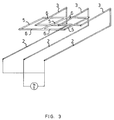
- Figure 3 shows a modification of the adjustment of the compensating coil.
- Figure 1 shows an apparatus intended for the heating treatment of material 1 passing as a continuous web.
- Material 1 can be supposed to be, for instance, paper web.
- the apparatus comprises electrodes 2 arranged to lie across the web and being alternately connected to the opposite potentials of the high-frequency power supply G.
- a conductor 3 is conducted from the opposite end of each electrode with respect to the power supply end, installed substantially parallel to the electrode.
- Conductor 3 is conducted at such a distance from its electrode 2 that the air gap that is formed guarantees a sufficient electric breakdown strength.
- Conductor 3 is stretched over a substantial part of the length of electrode 2, which in practice has proved to be at least two-thirds of the electrode length.
- short-circuit elements 4 are arranged, by which the conductor can be connected to the corresponding conductor of the adjacent electrode.
- Conductor 3 of two adjacent electrodes and the short-circuit element 4 connecting them to each other form a compensating coil.
- the short-circuit elements can be displaced in longitudinal direction with respect to conductors 3 in order to adjust the compensating inductance to be accurate in each case.
- the first basic factor is the mutual distance of the electrode rods 2 in the travel direction or web direction of the material to be processed.
- the need of voltage to be supplied to the electrodes increases with growing distance.
- the increased supply voltage influences the compensating inductances.
- the mutual distance of the electrodes may vary case by case from a few centimetres to tens of centimetres, for example, to dimensions of some 20-30 centimetres. A dimension of 10-15 centimetres can be considered a general value.
- the distance of the inductance coil from the electrodes is primarily determined according to the electric breakdown strength.
- the distance can also be used to affect the compensating inductance; at the greater a distance the inductance coil is located from the electrodes, the smaller the inductance effect is.
- This circumstance can be used for adjusting the compensation effect by varying the distance of the inductance conductors from the electrode at various points of the compensating range.
- a distance of some 20 centimetres can be considered the maximum distance between the electrode and the inductance conductor.
- the diameter of both the electrode and the inductance conductor also has its own effect on the dimensioning of the apparatus. The minimum diameter is determined by the heating caused by the current to be conducted.
- a diameter of some 10-40 mm can be considered conventional, although dimensions even up to some 100 mm occur.
- the electrode rods may also be connected over an inductance or a capacitance to the adjacent rod at the opposite end with respect to the current supply end in order to bring about a phase displacement between the rods.
- the arrangement can be applied in which compensating points are located in sequence over the length of several electrodes 2.
- the compensating inductance coil is formed by conductor 3 connected to the electrode at the compensating point, which is conducted at least at the distance of said electric breakdown strength from the electrode.
- the adjacent coil conductors 3 are connected to each other by an additional coil 7, which is equipped with a short-circuit element 4 provided for the adjustment of inductance at its end.
- the so-called transmission line theory can be applied as a numerical basis, by which, based on given simplifying assumptions, approximative values may be determined for the inductances, and diameter of the inductance conductors and distance from the electrode, if the approximative length according to the two-wire calculation model is known.
- the reducing effect of the inductance coil on the electrode inductance must be considered, which, in addition to other uncertainty factors, results in the need of adding some 10-20% to the calculated length of the inductance coil.
- the final adjustment of the inductance is carried out by experiments on the displacement of the short-circuit element 4.
- a stray-field electrode system is given, with which a 4-metre wide, thin material web, e.g. paper web is heated by using the current supply frequency of 13.56 MHz. Diameters of the electrodes are 50 mm and their mutual distance is 200 mm. The voltage value is assumed to be 5 kV. The required air gap between the inductance conductor and the electrode thus is 50 mm (1 kV/cm). A diameter of 15 mm is chosen for the conductors of the compensating inductances in order to keep the heat development in the conductors under control. The dimension of 3.5 m of the loop, parallel to the electrode, is numerically achieved. To this dimension, an adjusting margin of some 10% is to be added, and thus it can be established that the coil reaches over some 95% of the electrode length.
- Figure 3 shows an implementation alternative to this adjustment.
- a short-circuited inductance coil is located, which is arranged to be adjusted in the longitudinal direction of conductors 3 at its position. By this adjustment at position, the magnitude of the compensating inductance may be influenced.
Landscapes
- Electromagnetism (AREA)
- Physics & Mathematics (AREA)
- Engineering & Computer Science (AREA)
- Microbiology (AREA)
- Life Sciences & Earth Sciences (AREA)
- General Engineering & Computer Science (AREA)
- Biotechnology (AREA)
- Biomedical Technology (AREA)
- Molecular Biology (AREA)
- Mechanical Engineering (AREA)
- Health & Medical Sciences (AREA)
- Physical Or Chemical Processes And Apparatus (AREA)
- General Induction Heating (AREA)
- Solid State Image Pick-Up Elements (AREA)
- Electrostatic Spraying Apparatus (AREA)
- Medicinal Preparation (AREA)
- Pharmaceuticals Containing Other Organic And Inorganic Compounds (AREA)
- Drying Of Solid Materials (AREA)
- Constitution Of High-Frequency Heating (AREA)
- Plasma Technology (AREA)
- Discharge Heating (AREA)
Abstract
Description
- Object of the present invention is a method and an apparatus for the reduction of distance-dependent voltage increase of electrodes occurring in an apparatus comprising parallel, rod-like electrodes connected to a high-frequency voltage source, according is the preamble of
claims - Electrode structures of said type are used, for example, in heating and/or drying of various material webs, sheets or layers with high-frequency energy. The material to be treated in said machines is passed close to the rod-like electrodes, several of which are placed in parallel essentially transversely with respect to the travel direction of the material.
- The parallel electrodes are alternately connected to the high-frequency power supply for the purpose of forming an electromagnetic field between the electrodes to be directed to primarily influence the material to be treated. If the material to be treated contains moisture or otherwise possesses similar dielectric properties, the high-frequency electromagnetic field that is formed between two electrodes mainly is directed to the material to be treated. If the material also has a high dielectric loss factor, the high-frequency field generates a heating effect in the material, which, in turn, results in the desired heating and/or drying of the material.
- Examples of applications for apparatuses of this type are heating of paper web, wood veneer or textile materials with the aim of drying the material or equalizing their moisture content, heating of layers with which the material are coated or which are absorbed in it, after-treatment of bakery products proceeding on a transport conveyor, heating of a powdery or grainy stuff layer proceeding on a conveyor, etc.
- In most applications, the material to be treated passes as a wide web or mat, across which the electrodes must reach in order to bring about the desired effect. Long electrodes are involved with the well known problem of standing waves causing an increase in the voltage with growing distance from the voltage supply point. In many applications, size restrictions of the apparatus and similar structural factors enable voltage supply to the electrodes only from one end, at the most from both ends of the electrode, thus limiting the possibilities to eliminate the voltage increase.
- As is well-known, the above structures have provided a solution for the reduction of voltage increase, in which iductive coils are connected between adjacent electrodes at fixed intervals. This arrangement provides a serviceable solution for the reduction of voltage increase, in case it is applicable as far as the other apparatus structure is concerned. In paper and wood veneer dryer, for instance, in which some 5-metre electrodes and an alternating voltage frequency of 13.56 MHz are used, the solution is capable of keeping the voltage within the range of ± 5% of the initial voltage (1.5 kV) along the entire electrode. Said solution requires two inductive coil connections along the rods.
- The above known technology, based on the use of so-called centralized compensating coils, suffers, however, from certain problems in a system containing several parallel electrodes. The structure is unfavourable in terms of space need. It is also prone to getting dirty, and a dirty apparatus is difficult to clean. Inaccuracy in dimensioning of the apparatus, caused by the mutual inductances of the compensating coils further presents a functional problem.
- A solution for the elimination of the voltage increase occurring in the electrodes, based on a different principle, has been introduced in the Finnish patent specification 55922. In this solution, the electrodes are combined into groups of two electrodes, and for them is arranged a common supply by using a supply conductor located between the electrodes at an equal distance from them. Supply points are favourably chosen at several points between the ends of the electrodes. By taking the frequency of the used alternating voltage properly into account when choosing the supply points, a compensating effect to the voltage in the electrodes can be achieved. Compensating of the electrode voltage is also influenced by the fact that the current of the supply cable and the current of the electrode at part of the electrode become opposite, and consequently the resulted induced magnetic fields are also opposite and partly effect in the compensating of the voltage occurring in the electrode.
- The effect of said, known apparatus can be substantially achieved in the desired form only when current is supplied to both ends of the conductor located between the electrodes. Although the apparatus specifically was developed to reduce problems occurring in long electrodes (electrode length smaller than approximately one fifth of the used wavelength), said current supply inevitably causes problems with such electrodes. Either is an own generator to be used for both supply ends, one at each side of the apparatus, or the other supply end is to be equipped with long conductors. Two separate generators tend to cause problems, the most crucial of which in terms of operation is synchronization of the generators. On the other hand, the use of long conductors may add to the problem of voltage increase, that originally was to be solved.
- In this known structure, however, the number of connection points between the supply conductors and the electrodes according to the operating principle of the apparatus is restricted. If current is supplied at both ends of the supply conductor, the supply points are limited to two additional points over the length of the electrodes. If current is supplied to one end of the supply conductor, current supply to the electrodes can only be reasonably implemented at one additional point along the electrode. The circumstances referred to above restrict the maximum length of the electrodes to no more than one fourth of the wavelength, as mentioned in the publication.
- According to the basic idea of the invention, the same compensating effect of the opposite magnetic fields generated by the reverse currents in compensating of the electrode voltage is used as in publication FI 55922, although implemented in such a way that the restrictions characteristic of the system known from publication FI 55922 can be avoided. According to the basic idea of the invention this can be achieved so that a magnetic field opposite to the magnetic field of the electrode is generated by arranging a return path for the electrode current from the compensating point at a distance from the electrode ensuring the avoidance of any electric discharges, and reaching to the distance to be compensated, and by connecting this return path essentially at its end with the corresponding return path of each adjacent electrode possessing an opposite potential.
- The special forms of implementation of the method according to the invention are shown in the enclosed dependent claims.
- To the apparatus to implement the method according to the invention, it is characteristic that a compensating conductor is arranged in the vicinity of each electrode, the conductor passing at least at a distance from the electrode ensuring the avoidance of any electric discharge, and reaching over a part of the length of the electrode; that the compensating conductor is connected to the compensating point of the electrode at its end away from the current supply point of the electrode, and, at its other end, to the end of the corresponding compensating conductor of each adjacent electrode.
- The invention is described based on the enclosed schematic drawing, in which Figure 1 illustrates a principal implementation of the method according to the invention for the heat treatment of web-like material, and
- Figure 2 illustrates a modification of the method.
- Figure 3 shows a modification of the adjustment of the compensating coil.
- Figure 1 shows an apparatus intended for the heating treatment of
material 1 passing as a continuous web.Material 1 can be supposed to be, for instance, paper web. The apparatus compriseselectrodes 2 arranged to lie across the web and being alternately connected to the opposite potentials of the high-frequency power supply G. According to the invention, aconductor 3 is conducted from the opposite end of each electrode with respect to the power supply end, installed substantially parallel to the electrode.Conductor 3 is conducted at such a distance from itselectrode 2 that the air gap that is formed guarantees a sufficient electric breakdown strength.Conductor 3 is stretched over a substantial part of the length ofelectrode 2, which in practice has proved to be at least two-thirds of the electrode length. - At the end range of the conductors, short-
circuit elements 4 are arranged, by which the conductor can be connected to the corresponding conductor of the adjacent electrode.Conductor 3 of two adjacent electrodes and the short-circuit element 4 connecting them to each other form a compensating coil. The short-circuit elements can be displaced in longitudinal direction with respect toconductors 3 in order to adjust the compensating inductance to be accurate in each case. - Many factors must be considered when dimensioning an apparatus of said type to ensure that the desired end result is achieved. The first basic factor is the mutual distance of the
electrode rods 2 in the travel direction or web direction of the material to be processed. The need of voltage to be supplied to the electrodes increases with growing distance. The increased supply voltage, in turn, influences the compensating inductances. When operating the apparatus on radio frequencies, the mutual distance of the electrodes may vary case by case from a few centimetres to tens of centimetres, for example, to dimensions of some 20-30 centimetres. A dimension of 10-15 centimetres can be considered a general value. - The distance of the inductance coil from the electrodes is primarily determined according to the electric breakdown strength. The distance can also be used to affect the compensating inductance; at the greater a distance the inductance coil is located from the electrodes, the smaller the inductance effect is. This circumstance can be used for adjusting the compensation effect by varying the distance of the inductance conductors from the electrode at various points of the compensating range. A distance of some 20 centimetres can be considered the maximum distance between the electrode and the inductance conductor. The diameter of both the electrode and the inductance conductor also has its own effect on the dimensioning of the apparatus. The minimum diameter is determined by the heating caused by the current to be conducted. A diameter of some 10-40 mm can be considered conventional, although dimensions even up to some 100 mm occur.
- As distinct from the basic implementation form presented in the drawing figures, the electrode rods may also be connected over an inductance or a capacitance to the adjacent rod at the opposite end with respect to the current supply end in order to bring about a phase displacement between the rods. When using long electrodes, the arrangement can be applied in which compensating points are located in sequence over the length of
several electrodes 2. - In the implementation of Figure 2, for the sake of simplicity two
parallel electrodes 2 and the compensating inductance coil generated for them are illustrated. In compliance with the solution of Figure 1, the compensating inductance coil is formed byconductor 3 connected to the electrode at the compensating point, which is conducted at least at the distance of said electric breakdown strength from the electrode. To add the compensating inductance to the coil, theadjacent coil conductors 3 are connected to each other by anadditional coil 7, which is equipped with a short-circuit element 4 provided for the adjustment of inductance at its end. - When dimensioning the compensating inductance coil of the voltage increase, the so-called transmission line theory can be applied as a numerical basis, by which, based on given simplifying assumptions, approximative values may be determined for the inductances, and diameter of the inductance conductors and distance from the electrode, if the approximative length according to the two-wire calculation model is known. When defining the length, the reducing effect of the inductance coil on the electrode inductance must be considered, which, in addition to other uncertainty factors, results in the need of adding some 10-20% to the calculated length of the inductance coil. The final adjustment of the inductance is carried out by experiments on the displacement of the short-
circuit element 4. - In the following paragraph, a tangible dimensioning example is presented to illustrate the above.
- A stray-field electrode system is given, with which a 4-metre wide, thin material web, e.g. paper web is heated by using the current supply frequency of 13.56 MHz. Diameters of the electrodes are 50 mm and their mutual distance is 200 mm. The voltage value is assumed to be 5 kV. The required air gap between the inductance conductor and the electrode thus is 50 mm (1 kV/cm). A diameter of 15 mm is chosen for the conductors of the compensating inductances in order to keep the heat development in the conductors under control. The dimension of 3.5 m of the loop, parallel to the electrode, is numerically achieved. To this dimension, an adjusting margin of some 10% is to be added, and thus it can be established that the coil reaches over some 95% of the electrode length.
- As distinct from the above adjustment of the compensating inductances based on varying of the location of the short-
circuit elements 4, Figure 3 shows an implementation alternative to this adjustment. In the range of the end of eachconductor 3, a short-circuited inductance coil is located, which is arranged to be adjusted in the longitudinal direction ofconductors 3 at its position. By this adjustment at position, the magnitude of the compensating inductance may be influenced.
Claims (11)
- Method for the compensation of voltage increase, caused by the distance to the current supply point, of the electrodes (2) of a dielectric material processing apparatus comprising at least two rod-like, adjacent, parallel electrodes (2) and being connected at one end to an opposite high-frequency potential, for example, a radio frequency potential, by bringing at least along a part of the electrode (2) a reverse magnetic field to influence with the magnetic field of the electrode (2), characterized in that the magnetic field reverse to that of the electrode (2) is generated by arranging a return path (3) for the electrode current from the compensating point passing at least at a distance from the electrode (2) ensuring the avoidance of any electric discharges, and reaching over the distance to be compensated out, and in that this return path (3) is connected at its end to the corresponding return path (3) of each adjacent electrode (2), possessing an opposite potential.
- Method according to claim 1, characterized in that several compensating points are arranged along the electrode.
- Method according to claim 1 or 2, characterized in that one return path (3) per electrode (2) is arranged at each compensating point.
- Method according to claim 1 or 2, characterized in that several return conductors (3) per electrode (2) are arranged at each compensating point.
- Method according to any of the previous claims, characterized in that the return paths (3) are guided at varying distances from the electrodes (2).
- Method according to any of the previous claims, characterized in that the compensating inductance formed by two adjacent return paths (3) is adjusted by using a closed inductance coil, which is adjusted at its position in longitudinal direction with respect to the electrode (2), and which is located at an equal distance above or below the return conductor (3).
- Equipment for carrying out the method according to claim 1, comprising at least two adjacent and parallel electrodes (2), which at one end are connected to the opposite poles of a high-frequency power source (G), characterized in that in the vicinity of each electrode is arranged a compensating conductor (3) that passes at a distance from the electrode ensuring the avoidance any electric discharges and reaches over a part of the electrode (2) length; that the compensating conductor (3) is connected to the compensating point of the electrode (2) at the end away from the current supply point of the electrode (2), and, at its other end, is connected to the end of the corresponding compensating conductor (3) of each adjacent electrode (2).
- Equipment according to claim 7, characterized in that there are two or several compensating conductors (3) in sequence along the electrode (2), and that each of the conductors is connected to its own sequential compensating point of the electrode.
- Equipment according to claim 7 or 8, characterized in that the mutual connection point of the ends of the compensating conductors (3) of the adjacent electrodes (2) are adjustable with respect to the length of the conductor (3).
- Equipment according to claim 7 or 8, characterized in that the compensating conductors (3) of two adjacent electrodes (2) are connected to each other with interconnected (4) conductors (7) guided in induction influence with the adjacent compensating conductor (3).
- Equipment according to claim 7, characterized in that an inductance adjustment apparatus is located at the mutual connection point of the compensating conductors (3) of the electrodes (2), which comprises rods (5) that are parallel to the compensating conductors (3) and located at the same mutual distance, and conductors (6) connecting the rods at their ends.
Applications Claiming Priority (3)
| Application Number | Priority Date | Filing Date | Title |
|---|---|---|---|
| FI911816 | 1991-04-15 | ||
| FI911816A FI87127C (en) | 1991-04-15 | 1991-04-15 | Method for reducing distance dependent voltage rise in parallel high frequency electrodes |
| PCT/FI1992/000112 WO1992019082A1 (en) | 1991-04-15 | 1992-04-13 | Method and apparatus for the reduction of distance-dependent voltage increase of parallel high-frequency electrodes |
Publications (2)
| Publication Number | Publication Date |
|---|---|
| EP0533889A1 EP0533889A1 (en) | 1993-03-31 |
| EP0533889B1 true EP0533889B1 (en) | 1995-03-08 |
Family
ID=8532327
Family Applications (1)
| Application Number | Title | Priority Date | Filing Date |
|---|---|---|---|
| EP92908716A Expired - Lifetime EP0533889B1 (en) | 1991-04-15 | 1992-04-13 | Method and apparatus for the reduction of distance-dependent voltage increase of parallel high-frequency electrodes |
Country Status (8)
| Country | Link |
|---|---|
| US (1) | US5300749A (en) |
| EP (1) | EP0533889B1 (en) |
| JP (1) | JPH05508052A (en) |
| AT (1) | ATE119733T1 (en) |
| CA (1) | CA2085227A1 (en) |
| DE (1) | DE69201617T2 (en) |
| FI (1) | FI87127C (en) |
| WO (1) | WO1992019082A1 (en) |
Families Citing this family (7)
| Publication number | Priority date | Publication date | Assignee | Title |
|---|---|---|---|---|
| DE29517204U1 (en) * | 1995-10-31 | 1997-03-06 | Pollerhoff, Holger, 45279 Essen | Lock with very high protection against drilling |
| US6348679B1 (en) * | 1998-03-17 | 2002-02-19 | Ameritherm, Inc. | RF active compositions for use in adhesion, bonding and coating |
| US6649888B2 (en) | 1999-09-23 | 2003-11-18 | Codaco, Inc. | Radio frequency (RF) heating system |
| TW462212B (en) * | 2000-01-12 | 2001-11-01 | Via Tech Inc | Structure and method for decreasing mutual inductance between the adjacent conduction wires on the substrate |
| IT1392998B1 (en) * | 2009-02-12 | 2012-04-02 | Viv Internat S P A | LINE AND METHOD FOR SURFACE TREATMENT OF EXTENDED OBJECTS |
| US10137486B1 (en) * | 2018-02-27 | 2018-11-27 | Chevron U.S.A. Inc. | Systems and methods for thermal treatment of contaminated material |
| CN109176740B (en) * | 2018-09-30 | 2021-09-17 | 吉荣家具有限公司 | Wood cutting suspended magnetic traction device fixed and clamped by high-pressure gas |
Family Cites Families (8)
| Publication number | Priority date | Publication date | Assignee | Title |
|---|---|---|---|---|
| BE554517A (en) * | 1956-01-28 | |||
| CA780997A (en) * | 1964-01-23 | 1968-03-19 | M. Clark John | High frequency heating apparatus |
| DE1565005C3 (en) * | 1965-03-27 | 1975-06-26 | Philips Patentverwaltung Gmbh, 2000 Hamburg | High frequency heating device with waveguide |
| US3397454A (en) * | 1965-08-25 | 1968-08-20 | Talon Inc | Method and apparatus for forming composite electrical contacts |
| US3461263A (en) * | 1967-07-31 | 1969-08-12 | Radio Frequency Co Inc | Radio frequency heating apparatus |
| CA898902A (en) * | 1969-06-30 | 1972-04-25 | C. Clark James | H.f. heating apparatus |
| US4670634A (en) * | 1985-04-05 | 1987-06-02 | Iit Research Institute | In situ decontamination of spills and landfills by radio frequency heating |
| SE452077C (en) * | 1986-03-04 | 1992-12-07 | Blixt Autovision | DEVICE TO REDUCE UNWANTED LEAKFIELD ACTIVITIES IN FRONT OF CATHEDRAL TUBE SCREEN |
-
1991
- 1991-04-15 FI FI911816A patent/FI87127C/en not_active IP Right Cessation
-
1992
- 1992-04-13 JP JP92507672A patent/JPH05508052A/en active Pending
- 1992-04-13 EP EP92908716A patent/EP0533889B1/en not_active Expired - Lifetime
- 1992-04-13 DE DE69201617T patent/DE69201617T2/en not_active Expired - Fee Related
- 1992-04-13 AT AT92908716T patent/ATE119733T1/en not_active IP Right Cessation
- 1992-04-13 WO PCT/FI1992/000112 patent/WO1992019082A1/en not_active Ceased
- 1992-04-13 US US07/952,529 patent/US5300749A/en not_active Expired - Fee Related
- 1992-04-13 CA CA002085227A patent/CA2085227A1/en not_active Abandoned
Also Published As
| Publication number | Publication date |
|---|---|
| WO1992019082A1 (en) | 1992-10-29 |
| JPH05508052A (en) | 1993-11-11 |
| US5300749A (en) | 1994-04-05 |
| CA2085227A1 (en) | 1992-10-16 |
| DE69201617D1 (en) | 1995-04-13 |
| FI87127C (en) | 1992-11-25 |
| ATE119733T1 (en) | 1995-03-15 |
| FI87127B (en) | 1992-08-14 |
| FI911816A0 (en) | 1991-04-15 |
| EP0533889A1 (en) | 1993-03-31 |
| DE69201617T2 (en) | 1995-10-26 |
| FI911816A7 (en) | 1992-08-14 |
Similar Documents
| Publication | Publication Date | Title |
|---|---|---|
| US2546004A (en) | Progressive dielectric heating | |
| US4638571A (en) | Radio frequency nozzle bar dryer | |
| JPH10511539A (en) | Contactless inductive transmission device for electric power | |
| US1900843A (en) | Heater for rods and tubes | |
| US5300749A (en) | Method and apparatus for the reduction of distance-dependent voltage increase of parallel high-frequency electrodes | |
| US6963056B1 (en) | Induction heating of a workpiece | |
| JPH08501435A (en) | Contactless power distribution system | |
| KR20030031112A (en) | Improved dielectric heating using inductive coupling | |
| US2802085A (en) | Apparatus for the treatment of plastic materials | |
| GB802254A (en) | Improved method and apparatus for improving the adhesive properties of plastic materials | |
| US20230134296A1 (en) | Transformer Isolator Having RF Shield Structure for Effective Magnetic Power Transfer | |
| US4629851A (en) | Apparatus for heating a layer of dielectric material using radio frequency waves | |
| US3764768A (en) | Microwave applicator employing a broadside slot radiator | |
| US2503779A (en) | Device for radio frequency treatment of filamentary material | |
| US2562911A (en) | Dielectric heating system | |
| JP3213998B2 (en) | Resonant high frequency or microwave application device for heat treatment of continuously transported flat material | |
| CA2014289C (en) | Apparatus for heating a dielectric web or sheet material or for decreasing its moisture content | |
| US3495125A (en) | Quarter-wave transmission line radio frequency voltage step-up transformer | |
| US2765387A (en) | Dielectric heating system | |
| US3636637A (en) | Method and apparatus for drying liquid deposited on liquid receptive material | |
| US3681558A (en) | Capacitive high-frequency heating apparatus | |
| DK174056B1 (en) | Method and apparatus for heating media by high frequency electromagnetic waves | |
| US5818013A (en) | Process and device for inductive cross-field heating of flat metallic material | |
| JP6368471B2 (en) | Induction heating system and power supply method | |
| US2583128A (en) | Dual electrode tuning units for electric bonding machines |
Legal Events
| Date | Code | Title | Description |
|---|---|---|---|
| PUAI | Public reference made under article 153(3) epc to a published international application that has entered the european phase |
Free format text: ORIGINAL CODE: 0009012 |
|
| 17P | Request for examination filed |
Effective date: 19921202 |
|
| AK | Designated contracting states |
Kind code of ref document: A1 Designated state(s): AT BE CH DE DK ES FR GB GR IT LI LU MC NL SE |
|
| 17Q | First examination report despatched |
Effective date: 19940506 |
|
| GRAA | (expected) grant |
Free format text: ORIGINAL CODE: 0009210 |
|
| AK | Designated contracting states |
Kind code of ref document: B1 Designated state(s): AT BE CH DE DK ES FR GB GR IT LI LU MC NL SE |
|
| PG25 | Lapsed in a contracting state [announced via postgrant information from national office to epo] |
Ref country code: NL Free format text: LAPSE BECAUSE OF FAILURE TO SUBMIT A TRANSLATION OF THE DESCRIPTION OR TO PAY THE FEE WITHIN THE PRESCRIBED TIME-LIMIT Effective date: 19950308 Ref country code: MC Free format text: LAPSE BECAUSE OF NON-PAYMENT OF DUE FEES Effective date: 19950308 Ref country code: LI Effective date: 19950308 Ref country code: GR Free format text: LAPSE BECAUSE OF FAILURE TO SUBMIT A TRANSLATION OF THE DESCRIPTION OR TO PAY THE FEE WITHIN THE PRESCRIBED TIME-LIMIT Effective date: 19950308 Ref country code: ES Free format text: THE PATENT HAS BEEN ANNULLED BY A DECISION OF A NATIONAL AUTHORITY Effective date: 19950308 Ref country code: DK Effective date: 19950308 Ref country code: CH Effective date: 19950308 Ref country code: BE Effective date: 19950308 Ref country code: AT Effective date: 19950308 |
|
| REF | Corresponds to: |
Ref document number: 119733 Country of ref document: AT Date of ref document: 19950315 Kind code of ref document: T |
|
| REF | Corresponds to: |
Ref document number: 69201617 Country of ref document: DE Date of ref document: 19950413 |
|
| PGFP | Annual fee paid to national office [announced via postgrant information from national office to epo] |
Ref country code: DK Payment date: 19950425 Year of fee payment: 4 |
|
| PG25 | Lapsed in a contracting state [announced via postgrant information from national office to epo] |
Ref country code: LU Free format text: LAPSE BECAUSE OF NON-PAYMENT OF DUE FEES Effective date: 19950430 |
|
| ITF | It: translation for a ep patent filed | ||
| REG | Reference to a national code |
Ref country code: CH Ref legal event code: PL |
|
| ET | Fr: translation filed | ||
| NLV1 | Nl: lapsed or annulled due to failure to fulfill the requirements of art. 29p and 29m of the patents act | ||
| PLBE | No opposition filed within time limit |
Free format text: ORIGINAL CODE: 0009261 |
|
| 26N | No opposition filed | ||
| PGFP | Annual fee paid to national office [announced via postgrant information from national office to epo] |
Ref country code: GB Payment date: 19960313 Year of fee payment: 5 |
|
| PGFP | Annual fee paid to national office [announced via postgrant information from national office to epo] |
Ref country code: DE Payment date: 19960314 Year of fee payment: 5 |
|
| PGFP | Annual fee paid to national office [announced via postgrant information from national office to epo] |
Ref country code: FR Payment date: 19960318 Year of fee payment: 5 |
|
| PGFP | Annual fee paid to national office [announced via postgrant information from national office to epo] |
Ref country code: SE Payment date: 19960321 Year of fee payment: 5 |
|
| PG25 | Lapsed in a contracting state [announced via postgrant information from national office to epo] |
Ref country code: GB Effective date: 19970413 |
|
| PG25 | Lapsed in a contracting state [announced via postgrant information from national office to epo] |
Ref country code: SE Effective date: 19970414 |
|
| GBPC | Gb: european patent ceased through non-payment of renewal fee |
Effective date: 19970413 |
|
| PG25 | Lapsed in a contracting state [announced via postgrant information from national office to epo] |
Ref country code: FR Free format text: LAPSE BECAUSE OF NON-PAYMENT OF DUE FEES Effective date: 19971231 |
|
| PG25 | Lapsed in a contracting state [announced via postgrant information from national office to epo] |
Ref country code: DE Free format text: LAPSE BECAUSE OF NON-PAYMENT OF DUE FEES Effective date: 19980101 |
|
| EUG | Se: european patent has lapsed |
Ref document number: 92908716.1 |
|
| REG | Reference to a national code |
Ref country code: FR Ref legal event code: ST |
|
| PG25 | Lapsed in a contracting state [announced via postgrant information from national office to epo] |
Ref country code: IT Free format text: LAPSE BECAUSE OF NON-PAYMENT OF DUE FEES Effective date: 20050413 |