EP0533629B1 - Method and device for supplying heated fresh air - Google Patents
Method and device for supplying heated fresh air Download PDFInfo
- Publication number
- EP0533629B1 EP0533629B1 EP92810720A EP92810720A EP0533629B1 EP 0533629 B1 EP0533629 B1 EP 0533629B1 EP 92810720 A EP92810720 A EP 92810720A EP 92810720 A EP92810720 A EP 92810720A EP 0533629 B1 EP0533629 B1 EP 0533629B1
- Authority
- EP
- European Patent Office
- Prior art keywords
- air
- fresh air
- outflowing
- kitchen
- fresh
- Prior art date
- Legal status (The legal status is an assumption and is not a legal conclusion. Google has not performed a legal analysis and makes no representation as to the accuracy of the status listed.)
- Expired - Lifetime
Links
Images
Classifications
-
- F—MECHANICAL ENGINEERING; LIGHTING; HEATING; WEAPONS; BLASTING
- F24—HEATING; RANGES; VENTILATING
- F24F—AIR-CONDITIONING; AIR-HUMIDIFICATION; VENTILATION; USE OF AIR CURRENTS FOR SCREENING
- F24F7/00—Ventilation
- F24F7/04—Ventilation with ducting systems, e.g. by double walls; with natural circulation
- F24F7/06—Ventilation with ducting systems, e.g. by double walls; with natural circulation with forced air circulation, e.g. by fan positioning of a ventilator in or against a conduit
- F24F7/08—Ventilation with ducting systems, e.g. by double walls; with natural circulation with forced air circulation, e.g. by fan positioning of a ventilator in or against a conduit with separate ducts for supplied and exhausted air with provisions for reversal of the input and output systems
-
- F—MECHANICAL ENGINEERING; LIGHTING; HEATING; WEAPONS; BLASTING
- F24—HEATING; RANGES; VENTILATING
- F24F—AIR-CONDITIONING; AIR-HUMIDIFICATION; VENTILATION; USE OF AIR CURRENTS FOR SCREENING
- F24F12/00—Use of energy recovery systems in air conditioning, ventilation or screening
- F24F12/001—Use of energy recovery systems in air conditioning, ventilation or screening with heat-exchange between supplied and exhausted air
-
- Y—GENERAL TAGGING OF NEW TECHNOLOGICAL DEVELOPMENTS; GENERAL TAGGING OF CROSS-SECTIONAL TECHNOLOGIES SPANNING OVER SEVERAL SECTIONS OF THE IPC; TECHNICAL SUBJECTS COVERED BY FORMER USPC CROSS-REFERENCE ART COLLECTIONS [XRACs] AND DIGESTS
- Y02—TECHNOLOGIES OR APPLICATIONS FOR MITIGATION OR ADAPTATION AGAINST CLIMATE CHANGE
- Y02B—CLIMATE CHANGE MITIGATION TECHNOLOGIES RELATED TO BUILDINGS, e.g. HOUSING, HOUSE APPLIANCES OR RELATED END-USER APPLICATIONS
- Y02B30/00—Energy efficient heating, ventilation or air conditioning [HVAC]
- Y02B30/56—Heat recovery units
Definitions
- the invention relates to a device according to the preamble of the first claim.
- the used air is simply extracted by means of a fan, whereby fresh air often fills the vacuum created from adjacent rooms or from outside.
- the temperature is reduced because the air in the room contains thermal energy that is lost through ventilation. This thermal energy, which comes from the lighting, from the bath water or from the cooking or rinsing process and is released into the room air, flows unused into the ambient air outside the room or house.
- DE-A-33 10 569 discloses an embodiment for only multi-storey buildings, each with a fan for the supply and exhaust air, the connection of the individual pipe parts to one another to reduce the space requirement in the installation shaft is described in detail.
- DE-A-37 37 597 (D1) describes a device with a vacuum blower for heat exchange in a cattle shed.
- Two coaxially arranged tubes are provided, at the outlet of which there is a single blower with two blade rings, which can be switched between two blowing directions. Since the facility is primarily intended for one-piece cattle stalls, the design is only suitable for one-story buildings. In addition, it does not meet the higher requirements that are placed in a residential or office building with regard to the installation and extraction of odors, since the odors do not play a role in livestock houses.
- CH-A-0 678 443 (D3) describes a double-draft chimney made of composite duct components and their connection for supplying combustion air to heating systems.
- the object of the invention is to provide a device which does not have the disadvantages of the existing designs and is suitable for both single and multi-storey residential and office buildings for ventilation of bathrooms and kitchens with heat recovery.
- the heat energy present in the used air is used for room heating, it being important that the used air leaves the room as completely as possible, so that neither moisture nor odors remain.
- the device is intended for use in bathrooms and kitchens.
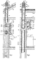
- FIG. 1 shows a bathroom with a floor 1, a ceiling 2 and an inner wall or facing 3 and an outer or load-bearing wall, rear wall or fastening wall 4, both of which form a ventilation shaft 13.
- a wash basin 5 with water inlet 6 and water outlet 7 and a mirror cabinet 8 with a mirror 9 and a shelf 10.
- Below the shelf 10 is a body in which an air outlet 11 with a filter is installed.
- an air inlet 12 At the top of the cabinet 8 is an air inlet 12 with a filter for the exhaust air, which is combined as possible with the lighting.
- the ventilation shaft 13 there are two pipes 14 and 15 arranged one inside the other, the pipe 14 preferably being arranged coaxially in the pipe 15.
- These two tubes 14, 15 mostly have a circular cross section, but can also have any other cross section and are, for example, square or square.
- the shaft 13 extends is normally determined by the number of floors of the building used for these rooms from a point above the flat or pitched roof 17 to below the lowest ventilated room and ends there with a rainwater collecting piece 41.
- the two pipes are surrounded by heat and sound insulation 16, which is only indicated in the upper roof area.
- This insulation 16 can also be used as fire and condensate protection insulation.
- An exhaust device 18 is used to transport away the used, mostly very humid air in the direction of arrow 23 from the bathroom, e.g. through the inner tube 14. This is done using suitable tube connections and a fan 18 with a backflow flap, which is switched on or off either manually or automatically.
- the automatic operation of the fan 20 with a backflow flap is e.g. controlled by a light contact switch with overrun relay.
- a fresh air supply device 19 For the supply of fresh air, a fresh air supply device 19 is provided, which is also equipped with a fan 21 with a backflow flap and can be controlled simultaneously with the exhaust air device 18. The device 19 blows fresh air in the direction of arrow 24 into the bathroom.
- a funnel-like pipe end 22 is arranged on the roof for the fresh air at the upper end of the pipe, which enables air to be supplied approximately in the radial direction along the arrows 36.
- the exhaust air 39 is expelled vertically in order to prevent mixing with the fresh air.
- backflow flaps are installed on the fans 20, 21.
- FIG. 2 shows a section through a kitchen in a building with a flat roof 25, it being possible for a sloping 17 or flat roof 25 to be used in the two figures.
- a kitchen is about removing the smells and vapors caused by cooking and supplying fresh air to the kitchen in the stove area.
- Above the cooker 26 there is a hood or kitchen suction device 28 with an exhaust fan of a conventional type, an adjustable flap or pull-out device 27 being mostly integrated.
- This opening 30 can also be provided with a filter.
- the fan 31 draws the fresh air through a pipe 33 which is connected to the annular space between the two pipes 14, 15, which are preferably arranged coaxially one inside the other.
- a pipe 34 as a connection between the suction hood and the inner pipe 14 is located approximately parallel to the pipe 33 for the fresh air supply.
- 1 is a bathroom, toilet or other room with similar ventilation systems.
- 2 is a kitchen or room with similar ventilation systems, e.g. with heavily polluted air.
- the pipe end 22 is provided for two pipes 14 and 15 and is intended to prevent the exhaust air from being sucked in again immediately and fed into the bathroom or the kitchen.
- This can be improved, for example, in that the speed of the outflowing air at the roof passage increases, but the fresh air is supplied through side openings 36. This arrangement prevents mixing of the air flows.
- the heat exchange takes place between the two pipes 14 and 15, in that the cold fresh air flowing between the two pipes 14, 15 extracts its heat from the inner pipe 14, which is consequently cooled and thus heats the incoming fresh air by the energy of the outgoing air.
- baffles or other metal bodies are inserted between the two tubes, which enlarge the surfaces and thus increase the heat emission.
- inspection doors 38, 39 are provided for the exhaust air and the fresh air. These doors or lids 38, 39 can be opened or unscrewed for cleaning or for filter replacement.
- the rear wall of the spice cabinet is preferably designed to be removable for the purpose of cleaning the fresh air fan 31 and the pipes, so that the removal can be carried out simply and quickly.
- connection 37 is not siphoned, since a permanent filling of the siphon is not guaranteed and thus channel gases could penetrate into the ventilation system, which is why the water is fed to the waste water through a siphon in use.
- annular space can contain baffles, which e.g. Route helically around the inner channel.
- An advantage of the present embodiment is based on the fact that the fans are located in a soundproof housing and therefore very favorable sound values can be achieved.
- tubes with a circular cross section are suitable as tubes, but also tubes with a square cross section.
- the cross-section of the pipes is preferably largely adapted to that of the shaft.
- the device described is suitable for both new buildings and conversions.
Abstract
Description
Die Erfindung betrifft eine Einrichtung gemäss dem Oberbegriff des ersten Patentanspruches.The invention relates to a device according to the preamble of the first claim.
Zum Belüften und Beheizen von gefangenen Räumen, wie Badezimmern und Küchen, wird die verbrauchte Luft einfach mittels eines Ventilators abgesaugt, wobei Frischluft oft aus Nebenräumen oder von aussen das enstandene Vakuum füllt. Bei diesem Vorgang findet gleichzeitig eine Temperaturreduktion statt, weil die im Raume vorhandene Luft Wärmeenergie enthält, die durch die Belüftung verlorengeht. Diese von der Beleuchtung, vom Badewasser oder vom Koch- oder Spülvorgang herrührende und an die Raumluft abgegebene Wärmeenergie strömt ungenutzt in die Umgebungsluft ausserhalb des Raumes oder des Hauses aus.To ventilate and heat trapped rooms, such as bathrooms and kitchens, the used air is simply extracted by means of a fan, whereby fresh air often fills the vacuum created from adjacent rooms or from outside. In this process, the temperature is reduced because the air in the room contains thermal energy that is lost through ventilation. This thermal energy, which comes from the lighting, from the bath water or from the cooking or rinsing process and is released into the room air, flows unused into the ambient air outside the room or house.
DE-A-33 10 569 (D2) offenbart eine Ausführung für nur mehrgeschössige Bauwerke, mit je einem Gebläse für die Zu- und die Abluft, wobei die Verbindung der einzelnen Rohrteile miteinander zur Verringerung des Raumbedarfes im Installationsschacht ausführlich beschrieben ist.DE-A-33 10 569 (D2) discloses an embodiment for only multi-storey buildings, each with a fan for the supply and exhaust air, the connection of the individual pipe parts to one another to reduce the space requirement in the installation shaft is described in detail.
In der DE-A-37 37 597 (D1) ist eine Einrichtung mit einem Unterdruckgebläse für den Wärmeaustausch in einem Viehstall beschrieben. Dabei sind zwei koaxial angeordnete Rohre vorgesehen, an deren Auslass sich ein einziges Gebläse mit zwei Schaufelkränzen befindet, das zwischen zwei Blasrichtungen umschaltbar ist. Da die Einrichtung in erster Linie für einstückige Viehställe vorgesehen ist, ist sie von der Ausführung her nur für einstöckige Gebäude geeignet. Ausserdem erfüllt sie nicht die höheren Anforderungen, die in einem Wohn- oder Bürohaus bezüglich Einbau und Abzug von Gerüchen gestellt werden, da die Gerüche in Viehställen keine Rolle spielen.DE-A-37 37 597 (D1) describes a device with a vacuum blower for heat exchange in a cattle shed. Two coaxially arranged tubes are provided, at the outlet of which there is a single blower with two blade rings, which can be switched between two blowing directions. Since the facility is primarily intended for one-piece cattle stalls, the design is only suitable for one-story buildings. In addition, it does not meet the higher requirements that are placed in a residential or office building with regard to the installation and extraction of odors, since the odors do not play a role in livestock houses.
CH-A-0 678 443 (D3) beschreibt einen Doppelzugschornstein aus zusammengesetzten Kanalbauelementen und deren Verbindung zur Zufuhr von Verbrennungsluft zu Heizungsanlagen.CH-A-0 678 443 (D3) describes a double-draft chimney made of composite duct components and their connection for supplying combustion air to heating systems.
Aufgabe der Erfindung ist die Schaffung einer Einrichtung, welche nicht die Nachteile der bestehenden Ausführungen aufweist und sowohl für ein- als auch für mehrstöckige Wohn- und Bürogebäude zur Be- und Entlüftung von Badezimmern und Küchen mit Wärmerückgewinnung geeignet ist.The object of the invention is to provide a device which does not have the disadvantages of the existing designs and is suitable for both single and multi-storey residential and office buildings for ventilation of bathrooms and kitchens with heat recovery.
Dabei ist ein möglichst weitgehender Luftaustausch in den zu belüftenden Räumen erwünschtThe greatest possible exchange of air in the rooms to be ventilated is desirable
Diese Aufgabe wird durch die Merkmale im Kennzeichnungsteil des ersten Anspruches gelöst.This object is achieved by the features in the characterizing part of the first claim.
Ausführungsformen sind in den abhängigen Ansprüchen umschrieben.Embodiments are described in the dependent claims.
Bei dieser Einrichtung wird die in der verbrauchten Luft vorhandene Wärmeenergie zur Raumheizung benutzt, wobei es wichtig ist, dass die verbrauchte Luft den Raum möglichst vollständig verlässt, so dass weder Feuchtigkeit noch Gerüche zurückbleiben.With this device, the heat energy present in the used air is used for room heating, it being important that the used air leaves the room as completely as possible, so that neither moisture nor odors remain.
Die Einrichtung ist zur Verwendung in Badzimmern und Küchen, vorgesehen.The device is intended for use in bathrooms and kitchens.
Nachfolgend werden Ausführungsbeispiele des Gegenstands der Erfindung anhand der Zeichnung näher erläutert. Es zeigen:
- Fig. 1
- einen Vertikalschnitt durch eine Badzimmerwand mit einem Luftschacht, und
- Fig. 2
- wie Fig. 1, jedoch durch eine Küchenwand.
- Fig. 1
- a vertical section through a bathroom wall with an air shaft, and
- Fig. 2
- like Fig. 1, but through a kitchen wall.
Fig. 1 zeigt ein Badzimmer mit einem Boden 1, einer Decke 2 sowie einer inneren Wand oder Vormauerung 3 und einer äusseren oder tragenden Wand, Rückwand oder Befestigungswand 4, die beide einen Lüftungsschacht 13 bilden. Im Badezimmer befindet sich ein Waschbecken 5 mit Wassereinlass 6 und Wasserauslass 7 sowie ein Spiegelschrank 8 mit einem Spiegel 9 und einem Tablar 10. Unterhalb des Tablars 10 befindet sich ein Körper, in dem ein Luftaustritt 11 mit Filter eingebaut ist. Zuoberst auf dem Schrank 8 ist ein möglichst mit der Beleuchtung kombinierter Lufteintritt 12 mit Filter für die Abluft eingebaut.1 shows a bathroom with a floor 1, a ceiling 2 and an inner wall or facing 3 and an outer or load-bearing wall, rear wall or fastening wall 4, both of which form a ventilation shaft 13. In the bathroom there is a wash basin 5 with water inlet 6 and water outlet 7 and a
Im Lüftungsschacht 13 befinden sich zwei ineinander angeordnete Rohre 14 und 15, wobei das Rohr 14 vorzugsweise koaxial im Rohr 15 angeordnet ist. Diese beiden Rohre 14,15 haben meistens einen kreisförmigen Querschnitt, können aber auch jeden anderen beliebigen Querschnitt aufweisen und sind z.B. viereckig oder auch quadratisch. Der Schacht 13 erstreckt sich normalerweise durch die Anzahl der für diese Räume genutzten Stockwerke des Gebäudes von einer Stelle oberhalb des Flach- oder Schrägdaches 17 bis unterhalb des untersten be- und entlüfteten Raumes und endet dort mit einem Regenwassersammelstück 41.In the ventilation shaft 13 there are two
Um den Wärmeverlust zu vermindern und die Geräusche zu dämpfen, sind die beiden Rohre von einer Wärme- und Schallisolation 16 umgeben, die lediglich im oberen Dachbereich angedeutet ist. Diese Isolation 16 kann ferner als Brand- und als Kondensatschutzisolation benutzt werden.In order to reduce the heat loss and to dampen the noise, the two pipes are surrounded by heat and
Eine Abluftvorrichtung 18 dient zum Wegtransport der verbrauchten, meistens sehr feuchten Luft in der Richtung des Pfeiles 23 aus dem Badezimmer, z.B. durch das Innenrohr 14. Dazu dienen passende Rohranschlüsse und ein Ventilator 18 mit Rückstauklappe, der entweder manuell oder automatisch einund ausgeschaltet wird. Der automatische Betrieb des Ventilators 20 mit Rückstauklappe wird z.B. von einem Lichtkontaktschalter mit Nachlaufrelais gesteuert.An exhaust device 18 is used to transport away the used, mostly very humid air in the direction of
Zur Zufuhr von Frischluft ist eine Frischluftzufuhrvorrichtung 19 vorgesehen, die ebenfalls mit einem Ventilator 21 mit Rückstauklappe ausgestattet ist und gleichzeitig mit der Abluftvorrichtung 18 gesteuert werden kann. Die Vorrichtung 19 bläst Frischluft in der Richtung des Pfeiles 24 in das Badezimmer.For the supply of fresh air, a fresh air supply device 19 is provided, which is also equipped with a fan 21 with a backflow flap and can be controlled simultaneously with the exhaust air device 18. The device 19 blows fresh air in the direction of arrow 24 into the bathroom.
Damit möglichst wenig Regenwasser in die Lüftung eindringt, ist für die Frischluft ein trichterartiger Rohrabschluss 22 am oberen Ende des Rohres auf dem Dach angeordnet, der eine Luftzufuhr etwa in radialer Richtung längs der Pfeile 36 ermöglicht. Die Abluft 39 wird senkrecht, um Vermischungen mit der Frischluft zu verhindern, nach oben ausgestossen. Das trotz dieser Massnahme eintretende Regenwasser sowie sich ansammelndes Kondenswasser fliessen durch die Rohre 14,15 nach unten und werden aus dem Sammelstück 41 mit einem Anschluss 37 dem Schmutzwasser zugeführt.So that as little rainwater as possible penetrates into the ventilation, a funnel-
Damit keine Gerüche in die einzelne Wohnungen eindringen, sind Rückstauklappen auf die Ventilatoren 20,21 aufgebaut.To ensure that no smells enter the individual apartments, backflow flaps are installed on the
In Fig. 2 ist ein Schnitt durch eine Küche in einem Gebäude mit Flachdach 25 gezeigt, wobei in den beiden Figuren ein Schräg- 17 oder Flachdach 25 verwendet werden kann. Bei einer Küche geht es darum, die durch das Kochen verursachten Gerüche und Dämpfe abzuleiten und der Küche im Herdbereich Frischluft zuzuführen. Über dem Herd 26 befindet sich eine Haube oder Küchenabsaugvorrichtung 28 mit Abluftventilator herkömmlicher Art, wobei meistens eine verstellbare Klappe oder Auszugsvorrichtung 27 integriert ist. Oberhalb der Absaugvorrichtung 28 befindet sich z.B. ein in die Haubenwandung eingebauter Gewürzschrank 29, der zuoberst in eine atzslüftungsöffnung 30 übergeht, hinter der sich ein Ventilatoreinheit 31 befindet, der Frischluft in der Richtung des Pfeiles 32 durch die Öffnung 30 einbläst. Diese Öffnung 30 kann auch mit einem Filter versehen sein. Der Ventilator 31 saugt die Frischluft durch ein Rohr 33, das mit dem Ringraum zwischen den beiden, vorzugsweise koaxial ineinander angeordneten Rohren 14,15 verbunden ist. Etwa parallel zum Rohr 33 für die Frischluftzufuhr befindet sich ein Rohr 34 als Verbindung zwischen der Absaughaube und dem Innenrohr 14.2 shows a section through a kitchen in a building with a
Bei der Ausführung gemäss Fig. 1 handelt es sich um Badezimmer, WCs oder andere Räume mit ähnlichen Lüftungsanlagen. Bei der Ausführung gemäss Fig. 2 handelt es sich um Küchen oder Räume mit ähnlichen Lüftungsanlagen, z.B. mit stark verschmutzter Luft.1 is a bathroom, toilet or other room with similar ventilation systems. 2 is a kitchen or room with similar ventilation systems, e.g. with heavily polluted air.
Der Rohrabschluss 22 ist für zwei Rohre 14 und 15 vorgesehen und soll verhindern, dass die Abluft sofort wieder eingesaugt und dem Badezimmer oder der Küche zugeführt wird. Dies kann z.B. dadurch verbessert werden, dass die Geschwindigkeit der ausströmenden Luft am Dachdurchtritt erhöht, jedoch die Frischluft durch seitliche Öffnungen 36 zugeführt wird. Diese Anordnung verhindert ein Vermischen der Luftströme.The
Der Wärmeaustausch findet zwischen den beiden Rohren 14 und 15 statt, indem die kalte, zwischen den beiden Rohren 14,15 fliessende Frichluft ihre Wärme dem Innenrohr 14 entzieht, das infolgedessen gekühlt wird und somit die einströmende Frischluft durch die Energie der ausströmenden Luft erwärmt. Damit der Wirkungsgrad des Wärmeaustauschers möglichst hoch ist, sind Leitbleche oder sonstige Metallkörper zwischen den beiden Rohren eingesetzt, welche die Oberflächen vergrössern und somit die Wärmeabgabe erhöhen.The heat exchange takes place between the two
An der Rückwand des Spiegelschrankes 8 oder einer sonstigen Einrichtung (Fig. 1) sind jeweils Revisionstüren 38,39 für die Ab- und die Frischluft vorgesehen. Diese Türen oder Deckel 38,39 können zur Reinigung oder zum Filteraustausch geöffnet oder abgeschraubt werden.On the rear wall of the
Bei der Ausführung für die Küche gemässs Fig. 2 wird vorzugsweise die Rückwand des Gewürzschrankes zecks Reinigung des Frischluftventilators 31 und der Rohrleitungen wegnehmbar gestaltet, so dass der Ausbau einfach und schnell durchführbar ist.In the embodiment for the kitchen according to FIG. 2, the rear wall of the spice cabinet is preferably designed to be removable for the purpose of cleaning the fresh air fan 31 and the pipes, so that the removal can be carried out simply and quickly.
Vorangehend wurde davon ausgegangen, dass nur zwei Rohre, vorzugsweise koaxial, ineinander angeordnet sind, so dass zwei Kanäle mit kreisförmigem Querschnitt entstehen, von welchen der eine ringförmig ist. In diesem Falle wird die verbrauchte Luft durch den inneren und die Frischluft durch den äusseren Kanal mit kreisförmigem Querschnitt geleitet.It was previously assumed that only two tubes, preferably coaxially, are arranged one inside the other, so that two channels with a circular cross section are formed, one of which is annular. In this case, the used air is led through the inner and the fresh air through the outer duct with a circular cross-section.
Der Anschluss 37 ist nicht syphoniert, da eine dauernde Füllung des Syphons nicht gewährleistet ist und somit Kanalgase in die Lüftungsanlage eindringen könnten, weshalb das Wasser durch einen im Gebrauch stehenden Syphon dem Abwasser zugeführt wird.The
Zudem kann der Ringraum Leitbleche enthalten, welche die Luft z.B. schraubenlinienförmig um den inneren Kanal leiten.In addition, the annular space can contain baffles, which e.g. Route helically around the inner channel.
Die Verwendung von Strömungshindernissen erfordert normalerweise eine höhere Leistung des Ventilators und kann evtl. zu nicht erwünschten Geräuschen führen. Zudem verlangt eine solche Ausführung häufiger eine Wartung als eine einfach ausgeführte Rohr- bzw. Doppelrohrleitung.The use of flow obstructions normally requires higher fan performance and may result in undesirable noise. In addition, such a design requires more maintenance than a simple pipe or double pipe.
Ein Vorteil der vorliegenden Ausführung ist darin begründet, dass die Ventilatoren in einem schallisolierten Gehäuse liegen und deshalb sehr günstige Schallwerte erreicht werden können.An advantage of the present embodiment is based on the fact that the fans are located in a soundproof housing and therefore very favorable sound values can be achieved.
Als Rohre sind nicht nur solche mit kreisförmigem Querschnitt geeignet, sondern auch solche mit viereckigem Querschnitt. Der Querschnitt der Rohre wird vorzugsweise möglichst weitgehend demjenigen des Schachts angepasst.Not only tubes with a circular cross section are suitable as tubes, but also tubes with a square cross section. The cross-section of the pipes is preferably largely adapted to that of the shaft.
Die beschriebene Einrichtung ist sowohl für Neu- als auch für Umbauten geeignet.The device described is suitable for both new buildings and conversions.
Claims (3)
- Device with roof outlet for ventilation of a bath or a kitchen in an office or appartment building with one or several floors through supply of fresh air heated by the outflowing used air by means of an inner and an outer pipe placed in one another in order to separate the inflowing from the outflowing air, in which the intake (11) for the used air and the outlet for the fresh air (12) are arranged spaced from each other in a wall chest (8,29), behind which ventilators (20,21) are located, the inner pipe being reserved for the outflowing while the circular space between the two pipes (14,15) is reserved for the inflowing air, said roof outlet (22) being provided with side openings (36) for air supply in radial direction and with a vertical opening (40) for the outflowing or used air, characterized in that fins are arranged between the tubes (14,15) in order to increase the interchange of heat between the two air flows, and that the lower end of the tubes (14,15) discharge into an enclosure for rain and condensed water, which enclosure is connected with the waste water from the hand basin, the bath or the kitchen flush cleaning.
- Device according to claim 1, characterized in that the ventilators (29,21) are controllable from a common control unit.
- Device according to claim 1, characterized in that the ventilators (20,21) are controllable from two separate control units.
Applications Claiming Priority (2)
| Application Number | Priority Date | Filing Date | Title |
|---|---|---|---|
| CH2806/91A CH680947A5 (en) | 1991-09-20 | 1991-09-20 | |
| CH2806/91 | 1991-09-20 |
Publications (2)
| Publication Number | Publication Date |
|---|---|
| EP0533629A1 EP0533629A1 (en) | 1993-03-24 |
| EP0533629B1 true EP0533629B1 (en) | 1997-04-02 |
Family
ID=4242013
Family Applications (1)
| Application Number | Title | Priority Date | Filing Date |
|---|---|---|---|
| EP92810720A Expired - Lifetime EP0533629B1 (en) | 1991-09-20 | 1992-09-21 | Method and device for supplying heated fresh air |
Country Status (4)
| Country | Link |
|---|---|
| EP (1) | EP0533629B1 (en) |
| AT (1) | ATE151163T1 (en) |
| CH (1) | CH680947A5 (en) |
| DE (1) | DE59208287D1 (en) |
Families Citing this family (10)
| Publication number | Priority date | Publication date | Assignee | Title |
|---|---|---|---|---|
| GB9420731D0 (en) * | 1994-10-14 | 1994-11-30 | Stokes Keith H | An improved heat exchange ventilator |
| DE29709935U1 (en) * | 1997-06-07 | 1997-08-07 | Schoeck Ag | Heat recovery device |
| DE19809974B4 (en) * | 1998-03-09 | 2010-07-08 | Krecké, Edmond Dominique | Building with air conditioning |
| ATE275717T1 (en) | 2000-02-23 | 2004-09-15 | Ursula Bach | HEAT RECOVERY DEVICE |
| NL1016063C2 (en) * | 2000-08-31 | 2002-03-01 | Gastec Nv | A gas transit provided with an indoor heat exchanger associated with a heat pump. |
| DE10046702B4 (en) * | 2000-09-21 | 2009-12-24 | Rayak, Mark, Dr.-Ing. | Natural ventilation system for cowsheds |
| FR2944340B1 (en) * | 2009-04-14 | 2012-08-17 | Iosis Concept | DOUBLE COAXIAL FLOW VENTILATION INSTALLATION WITH INTEGRATED HEAT PUMP FOR COLLECTIVE HOUSING |
| DE102010014872A1 (en) * | 2010-04-13 | 2011-10-13 | Erwin Grohmann | vent |
| RU2615710C1 (en) * | 2016-01-28 | 2017-04-07 | Общество с ограниченной ответственностью "Дёке Экстружн" | Deflector |
| DE102021105980A1 (en) | 2021-03-11 | 2022-09-15 | Werner Schallenberg | Air routing device for ventilating and venting a room in relation to an environment arranged outside of the room and ventilation arrangement with an air routing device and a device for controlled living space ventilation |
Family Cites Families (3)
| Publication number | Priority date | Publication date | Assignee | Title |
|---|---|---|---|---|
| DE3310569A1 (en) * | 1983-03-23 | 1984-09-27 | Robert Dipl.-Ing.(FH) 8000 München Spieldiener | Ventilating and venting plant for multi-storey buildings |
| GB2212224A (en) * | 1987-11-05 | 1989-07-19 | Karjasuo Oy | Fan |
| CH678443A5 (en) * | 1989-03-10 | 1991-09-13 | Schlegel Ag H | Double flue chimney - comprises pipes and casing of ductile material without concrete brickwork or ceramic material |
-
1991
- 1991-09-20 CH CH2806/91A patent/CH680947A5/de not_active IP Right Cessation
-
1992
- 1992-09-21 AT AT92810720T patent/ATE151163T1/en not_active IP Right Cessation
- 1992-09-21 EP EP92810720A patent/EP0533629B1/en not_active Expired - Lifetime
- 1992-09-21 DE DE59208287T patent/DE59208287D1/en not_active Expired - Fee Related
Also Published As
| Publication number | Publication date |
|---|---|
| ATE151163T1 (en) | 1997-04-15 |
| EP0533629A1 (en) | 1993-03-24 |
| CH680947A5 (en) | 1992-12-15 |
| DE59208287D1 (en) | 1997-05-07 |
Similar Documents
| Publication | Publication Date | Title |
|---|---|---|
| EP2405207B1 (en) | Air-conditioning device for integration in a ceiling | |
| EP0533629B1 (en) | Method and device for supplying heated fresh air | |
| DE202004008792U1 (en) | A building ventilation system has fan assisted extraction of air from rooms and entry to a vertical chimney only in the roof space or cellar | |
| DE202007008504U1 (en) | Device for room ventilation | |
| DE4135130C2 (en) | Ventilation system for living rooms in apartments | |
| DE102008005364A1 (en) | Under-floor panel convector, has air outlet directly arranged besides air outlet opening and connectable with primary air source, where air exhaust direction of air outlet is parallel to air exhaust direction of blower | |
| DE4134305C2 (en) | Fresh air system | |
| AT500559B1 (en) | ROOM TECHNOLOGY | |
| EP1130332B1 (en) | Heat recovery device | |
| DE10255172A1 (en) | Small-scale modular ventilation system for a single room has a basic unit with control unit, condensed water trap and an ambient air inlet/outlet pipe | |
| DE19852640A1 (en) | Chimney for a domestic heating system | |
| EP2175209B9 (en) | Calorific value heater | |
| DE3804232A1 (en) | Method and apparatus for room cooling | |
| DE2748772A1 (en) | Multi-storey building ventilation shaft - has blower fan above cellar and Pitot tubes forming ejectors at storeys | |
| AT413756B (en) | ROOM AIR FACILITY | |
| DE202006000106U1 (en) | Convector heater for shielding cold radiation in building, has piping system forming section that is arranged in parallel to ceiling section, and separation unit separating housing area based on process of separation of system`s areas | |
| DE102006039161B3 (en) | Sauna cabin with exhaust air element, has exhaust air wall element with exhaust air duct provided in interior of cabin having exhaust air entrance opening and on outside of cabin is exhaust air outlet | |
| DE69829277T2 (en) | CEILING CONSTRUCTION FOR HEATING OR COOLING A ROOM | |
| DE102006053355B4 (en) | Heating and ventilation device | |
| EP1939530B1 (en) | Supplementary device for stoves | |
| DE19533593C2 (en) | Bath room with multiple ventilation | |
| DE10135842B4 (en) | Votive light stand | |
| DE202023106934U1 (en) | Outdoor unit arrangement of heat pumps | |
| WO2023089138A1 (en) | System for climate-control of interior spaces of a building | |
| DE3105401A1 (en) | Ventilating system for buildings |
Legal Events
| Date | Code | Title | Description |
|---|---|---|---|
| PUAI | Public reference made under article 153(3) epc to a published international application that has entered the european phase |
Free format text: ORIGINAL CODE: 0009012 |
|
| AK | Designated contracting states |
Kind code of ref document: A1 Designated state(s): AT CH DE DK FR IT LI SE |
|
| 17P | Request for examination filed |
Effective date: 19930917 |
|
| 17Q | First examination report despatched |
Effective date: 19940721 |
|
| GRAG | Despatch of communication of intention to grant |
Free format text: ORIGINAL CODE: EPIDOS AGRA |
|
| GRAH | Despatch of communication of intention to grant a patent |
Free format text: ORIGINAL CODE: EPIDOS IGRA |
|
| GRAH | Despatch of communication of intention to grant a patent |
Free format text: ORIGINAL CODE: EPIDOS IGRA |
|
| GRAA | (expected) grant |
Free format text: ORIGINAL CODE: 0009210 |
|
| AK | Designated contracting states |
Kind code of ref document: B1 Designated state(s): AT CH DE DK FR IT LI SE |
|
| REF | Corresponds to: |
Ref document number: 151163 Country of ref document: AT Date of ref document: 19970415 Kind code of ref document: T |
|
| REG | Reference to a national code |
Ref country code: CH Ref legal event code: EP |
|
| REF | Corresponds to: |
Ref document number: 59208287 Country of ref document: DE Date of ref document: 19970507 |
|
| PG25 | Lapsed in a contracting state [announced via postgrant information from national office to epo] |
Ref country code: SE Effective date: 19970702 Ref country code: DK Free format text: LAPSE BECAUSE OF FAILURE TO SUBMIT A TRANSLATION OF THE DESCRIPTION OR TO PAY THE FEE WITHIN THE PRESCRIBED TIME-LIMIT Effective date: 19970702 |
|
| ET | Fr: translation filed | ||
| PLBE | No opposition filed within time limit |
Free format text: ORIGINAL CODE: 0009261 |
|
| STAA | Information on the status of an ep patent application or granted ep patent |
Free format text: STATUS: NO OPPOSITION FILED WITHIN TIME LIMIT |
|
| 26N | No opposition filed | ||
| PGFP | Annual fee paid to national office [announced via postgrant information from national office to epo] |
Ref country code: DK Payment date: 19980925 Year of fee payment: 7 |
|
| PGFP | Annual fee paid to national office [announced via postgrant information from national office to epo] |
Ref country code: CH Payment date: 20050808 Year of fee payment: 14 |
|
| PG25 | Lapsed in a contracting state [announced via postgrant information from national office to epo] |
Ref country code: IT Free format text: LAPSE BECAUSE OF NON-PAYMENT OF DUE FEES;WARNING: LAPSES OF ITALIAN PATENTS WITH EFFECTIVE DATE BEFORE 2007 MAY HAVE OCCURRED AT ANY TIME BEFORE 2007. THE CORRECT EFFECTIVE DATE MAY BE DIFFERENT FROM THE ONE RECORDED. Effective date: 20050921 |
|
| PG25 | Lapsed in a contracting state [announced via postgrant information from national office to epo] |
Ref country code: LI Free format text: LAPSE BECAUSE OF NON-PAYMENT OF DUE FEES Effective date: 20060930 Ref country code: CH Free format text: LAPSE BECAUSE OF NON-PAYMENT OF DUE FEES Effective date: 20060930 |
|
| REG | Reference to a national code |
Ref country code: CH Ref legal event code: PL |
|
| PGFP | Annual fee paid to national office [announced via postgrant information from national office to epo] |
Ref country code: FR Payment date: 20080912 Year of fee payment: 17 Ref country code: AT Payment date: 20080915 Year of fee payment: 17 |
|
| PGFP | Annual fee paid to national office [announced via postgrant information from national office to epo] |
Ref country code: DE Payment date: 20080919 Year of fee payment: 17 |
|
| REG | Reference to a national code |
Ref country code: FR Ref legal event code: ST Effective date: 20100531 |
|
| PG25 | Lapsed in a contracting state [announced via postgrant information from national office to epo] |
Ref country code: AT Free format text: LAPSE BECAUSE OF NON-PAYMENT OF DUE FEES Effective date: 20090921 |
|
| PG25 | Lapsed in a contracting state [announced via postgrant information from national office to epo] |
Ref country code: FR Free format text: LAPSE BECAUSE OF NON-PAYMENT OF DUE FEES Effective date: 20090930 Ref country code: DE Free format text: LAPSE BECAUSE OF NON-PAYMENT OF DUE FEES Effective date: 20100401 |