EP0533554A1 - Kombinierter Wärmetauscher für Heizung und Brauchwasser mit nahtloserer Rohrwendel für die Brauchwasserheizung - Google Patents
Kombinierter Wärmetauscher für Heizung und Brauchwasser mit nahtloserer Rohrwendel für die Brauchwasserheizung Download PDFInfo
- Publication number
- EP0533554A1 EP0533554A1 EP92402523A EP92402523A EP0533554A1 EP 0533554 A1 EP0533554 A1 EP 0533554A1 EP 92402523 A EP92402523 A EP 92402523A EP 92402523 A EP92402523 A EP 92402523A EP 0533554 A1 EP0533554 A1 EP 0533554A1
- Authority
- EP
- European Patent Office
- Prior art keywords
- tubes
- heating
- circuit
- sanitary
- flattened
- Prior art date
- Legal status (The legal status is an assumption and is not a legal conclusion. Google has not performed a legal analysis and makes no representation as to the accuracy of the status listed.)
- Granted
Links
- 238000010438 heat treatment Methods 0.000 title claims abstract description 42
- XLYOFNOQVPJJNP-UHFFFAOYSA-N water Substances O XLYOFNOQVPJJNP-UHFFFAOYSA-N 0.000 title claims abstract description 38
- 238000004519 manufacturing process Methods 0.000 title abstract description 3
- 238000009434 installation Methods 0.000 claims abstract description 13
- 239000008236 heating water Substances 0.000 claims abstract description 12
- 238000005452 bending Methods 0.000 claims abstract description 11
- 238000003466 welding Methods 0.000 claims abstract description 3
- 239000000463 material Substances 0.000 claims description 2
- 238000005192 partition Methods 0.000 claims description 2
- 229920001296 polysiloxane Polymers 0.000 claims description 2
- WYTGDNHDOZPMIW-RCBQFDQVSA-N alstonine Natural products C1=CC2=C3C=CC=CC3=NC2=C2N1C[C@H]1[C@H](C)OC=C(C(=O)OC)[C@H]1C2 WYTGDNHDOZPMIW-RCBQFDQVSA-N 0.000 description 4
- 239000007789 gas Substances 0.000 description 4
- QEVHRUUCFGRFIF-MDEJGZGSSA-N reserpine Chemical compound O([C@H]1[C@@H]([C@H]([C@H]2C[C@@H]3C4=C(C5=CC=C(OC)C=C5N4)CCN3C[C@H]2C1)C(=O)OC)OC)C(=O)C1=CC(OC)=C(OC)C(OC)=C1 QEVHRUUCFGRFIF-MDEJGZGSSA-N 0.000 description 4
- 239000000470 constituent Substances 0.000 description 2
- 238000005476 soldering Methods 0.000 description 2
- 208000031968 Cadaver Diseases 0.000 description 1
- RYGMFSIKBFXOCR-UHFFFAOYSA-N Copper Chemical compound [Cu] RYGMFSIKBFXOCR-UHFFFAOYSA-N 0.000 description 1
- 238000000429 assembly Methods 0.000 description 1
- 229910052802 copper Inorganic materials 0.000 description 1
- 239000010949 copper Substances 0.000 description 1
- 239000000945 filler Substances 0.000 description 1
- 239000012530 fluid Substances 0.000 description 1
- 239000002184 metal Substances 0.000 description 1
- 229910052751 metal Inorganic materials 0.000 description 1
- 230000000737 periodic effect Effects 0.000 description 1
- 238000007789 sealing Methods 0.000 description 1
- 229910000679 solder Inorganic materials 0.000 description 1
- 239000000126 substance Substances 0.000 description 1
Images

Classifications
-
- F—MECHANICAL ENGINEERING; LIGHTING; HEATING; WEAPONS; BLASTING
- F28—HEAT EXCHANGE IN GENERAL
- F28F—DETAILS OF HEAT-EXCHANGE AND HEAT-TRANSFER APPARATUS, OF GENERAL APPLICATION
- F28F1/00—Tubular elements; Assemblies of tubular elements
- F28F1/02—Tubular elements of cross-section which is non-circular
-
- F—MECHANICAL ENGINEERING; LIGHTING; HEATING; WEAPONS; BLASTING
- F24—HEATING; RANGES; VENTILATING
- F24H—FLUID HEATERS, e.g. WATER OR AIR HEATERS, HAVING HEAT-GENERATING MEANS, e.g. HEAT PUMPS, IN GENERAL
- F24H1/00—Water heaters, e.g. boilers, continuous-flow heaters or water-storage heaters
- F24H1/48—Water heaters for central heating incorporating heaters for domestic water
- F24H1/52—Water heaters for central heating incorporating heaters for domestic water incorporating heat exchangers for domestic water
-
- F—MECHANICAL ENGINEERING; LIGHTING; HEATING; WEAPONS; BLASTING
- F28—HEAT EXCHANGE IN GENERAL
- F28D—HEAT-EXCHANGE APPARATUS, NOT PROVIDED FOR IN ANOTHER SUBCLASS, IN WHICH THE HEAT-EXCHANGE MEDIA DO NOT COME INTO DIRECT CONTACT
- F28D7/00—Heat-exchange apparatus having stationary tubular conduit assemblies for both heat-exchange media, the media being in contact with different sides of a conduit wall
- F28D7/0066—Multi-circuit heat-exchangers, e.g. integrating different heat exchange sections in the same unit or heat-exchangers for more than two fluids
- F28D7/0075—Multi-circuit heat-exchangers, e.g. integrating different heat exchange sections in the same unit or heat-exchangers for more than two fluids with particular circuits for the same heat exchange medium, e.g. with the same heat exchange medium flowing through sections having different heat exchange capacities or for heating or cooling the same heat exchange medium at different temperatures
-
- F—MECHANICAL ENGINEERING; LIGHTING; HEATING; WEAPONS; BLASTING
- F28—HEAT EXCHANGE IN GENERAL
- F28D—HEAT-EXCHANGE APPARATUS, NOT PROVIDED FOR IN ANOTHER SUBCLASS, IN WHICH THE HEAT-EXCHANGE MEDIA DO NOT COME INTO DIRECT CONTACT
- F28D7/00—Heat-exchange apparatus having stationary tubular conduit assemblies for both heat-exchange media, the media being in contact with different sides of a conduit wall
- F28D7/08—Heat-exchange apparatus having stationary tubular conduit assemblies for both heat-exchange media, the media being in contact with different sides of a conduit wall the conduits being otherwise bent, e.g. in a serpentine or zig-zag
- F28D7/082—Heat-exchange apparatus having stationary tubular conduit assemblies for both heat-exchange media, the media being in contact with different sides of a conduit wall the conduits being otherwise bent, e.g. in a serpentine or zig-zag with serpentine or zig-zag configuration
- F28D7/085—Heat-exchange apparatus having stationary tubular conduit assemblies for both heat-exchange media, the media being in contact with different sides of a conduit wall the conduits being otherwise bent, e.g. in a serpentine or zig-zag with serpentine or zig-zag configuration in the form of parallel conduits coupled by bent portions
-
- F—MECHANICAL ENGINEERING; LIGHTING; HEATING; WEAPONS; BLASTING
- F28—HEAT EXCHANGE IN GENERAL
- F28D—HEAT-EXCHANGE APPARATUS, NOT PROVIDED FOR IN ANOTHER SUBCLASS, IN WHICH THE HEAT-EXCHANGE MEDIA DO NOT COME INTO DIRECT CONTACT
- F28D7/00—Heat-exchange apparatus having stationary tubular conduit assemblies for both heat-exchange media, the media being in contact with different sides of a conduit wall
- F28D7/10—Heat-exchange apparatus having stationary tubular conduit assemblies for both heat-exchange media, the media being in contact with different sides of a conduit wall the conduits being arranged one within the other, e.g. concentrically
- F28D7/14—Heat-exchange apparatus having stationary tubular conduit assemblies for both heat-exchange media, the media being in contact with different sides of a conduit wall the conduits being arranged one within the other, e.g. concentrically both tubes being bent
Definitions
- the present invention relates to a central heating installation provided with a hot water circuit for domestic use or sanitary water and comprising a heating device comprising an envelope or ferrule, the lower part of which is provided with a burner, in particular of a gas burner and on which is wound or not a conduit in which the water circulates from the heating circuit, this circuit then crosses a bundle of fins located at the upper part of the envelope on the trajectory of the hot gases escaping from the latter to then be directed to a discharge pipe.
- European patent N ° 89,400,269 (priority French patent N ° 88.01800) describes a central heating installation in which the exchanger is mixed. It mainly comprises a set of tubes used for heating domestic water, shaped as a pin or coil which are arranged inside flattened tubes. Said tubes form a block connected by elbows and a set of fins, they constitute the heating water circuit, the sanitary water being heated by said water.
- This configuration ensures that the tubes of the domestic hot water circuit, arranged in a pin or coil in the flat tubes of the heating water circuit are not in contact with them.
- the dimensions of said flattened tubes and of said tubes are chosen so that the volume of water contained between the flattened tubes and the meanders of the hairpin tubes is as small as possible.
- This arrangement requires having at each end brazed or welded end pieces in order to close off the heating circuit as well as elbows serving to connect the respective circuits together.
- the present invention proposes to provide an improved installation which does not have the drawbacks mentioned above.
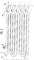
- Figure 1 is an overall perspective view of the assembly exploded showing the different constituents of the mixed exchanger A.
- Figure 2 is a perspective view of the tubes shaped as a series of pins in two perpendicular planes two by two.
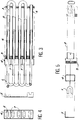
- Figure 3 is a plan view of the assembly of the mixed exchanger A.
- Figure 4 is a plan view in side elevation of the mixed exchanger A.
- Figure 5 is a plan view in front elevation during assembly of the mixed exchanger A.
- the heating appliance object of this invention, comprises a first duct 2 for heating the water of the central heating circuit and a second conduit 1 for heating domestic water.
- the duct 2 of the heating circuit is in the form of a series flattened tube pins such as 2 which each have a cross section of oval shape, the largest axis being horizontal.
- These tubes are connected at one of their ends by elbows obtained by bending these said tubes.
- the domestic water pipe 1 consists of a tube, preferably of circular cross section, disposed inside the flattened tubes 2 of the heating circuit, shaped into a series of pins obtained by bending said tube in two perpendicular planes two by two. This increases the heat exchange surface between the two circuits of the mixed exchanger since all the bends are in the heating circuit and not outside.
- the positioning of the tubes of the pin-shaped sanitary circuit arranged inside the flattened tubes of the heating circuit is carried out so that there is no physical contact between the walls of the tubes 1 and 2, and so that the volume of water contained in the residual annular space is as small as possible. It also results from this configuration that all the calories conveyed by the heating circuit are transferred into the sanitary water circuit.
- the respective assembly of the constituent sub-assemblies is as follows: the tubes 1 shaped as a hairpin of the sanitary water circuit, provided with plastic rings 6, are inserted inside the flattened tubes 2 of the water circuit of heating, while the fins 3 and the manifold 4 thread on the flattened tubes 2 of the heating circuit, the cover 5 completely closing off the assembly. This collector guarantees the routing of the heating fluid as well as the tightness of the assembly.
- This collector 4 maintains the two circuits of the exchanger. It is soldered to the heating water circuit.
- Reading the above description shows that the invention provides a heating installation ensuring perfect heat exchange between the two incorporated circuits of heating water and sanitary water thanks to a large heat exchange surface obtained by the configuration. the different circuits.
Landscapes
- Engineering & Computer Science (AREA)
- Physics & Mathematics (AREA)
- Thermal Sciences (AREA)
- Mechanical Engineering (AREA)
- General Engineering & Computer Science (AREA)
- Geometry (AREA)
- Chemical & Material Sciences (AREA)
- Combustion & Propulsion (AREA)
- Heat-Exchange Devices With Radiators And Conduit Assemblies (AREA)
- External Artificial Organs (AREA)
Applications Claiming Priority (2)
| Application Number | Priority Date | Filing Date | Title |
|---|---|---|---|
| FR9111556 | 1991-09-19 | ||
| FR9111556A FR2667399A1 (fr) | 1990-09-19 | 1991-09-19 | Procede et appareil de controle, notamment pour des recipients. |
Publications (2)
| Publication Number | Publication Date |
|---|---|
| EP0533554A1 true EP0533554A1 (de) | 1993-03-24 |
| EP0533554B1 EP0533554B1 (de) | 1995-01-18 |
Family
ID=9417101
Family Applications (1)
| Application Number | Title | Priority Date | Filing Date |
|---|---|---|---|
| EP92402523A Expired - Lifetime EP0533554B1 (de) | 1991-09-19 | 1992-09-15 | Kombinierter Wärmetauscher für Heizung und Brauchwasser mit nahtloserer Rohrwendel für die Brauchwasserheizung |
Country Status (4)
| Country | Link |
|---|---|
| EP (1) | EP0533554B1 (de) |
| AT (1) | ATE117425T1 (de) |
| DE (1) | DE69201226T2 (de) |
| ES (1) | ES2066582T3 (de) |
Citations (3)
| Publication number | Priority date | Publication date | Assignee | Title |
|---|---|---|---|---|
| FR2404178A1 (fr) * | 1977-09-23 | 1979-04-20 | Bosch Gmbh Robert | Transmetteur de chaleur pour un chauffe-eau a ecoulement libre chauffe au gaz ou a l'huile |
| FR2539219A1 (fr) * | 1983-01-11 | 1984-07-13 | Tesolin Luciano | Echangeur de chaleur a tubes d'eau coaxiaux a geometrie spiroidale pour chaudiere de chauffage et production d'eau chaude sanitaire pour bruleurs a gaz a aspiration d'air |
| FR2627266A1 (fr) * | 1988-02-16 | 1989-08-18 | Leblanc Sa E L M | Installation de chauffage central avec circuit d'eau chaude a usage sanitaire |
-
1992
- 1992-09-15 EP EP92402523A patent/EP0533554B1/de not_active Expired - Lifetime
- 1992-09-15 AT AT92402523T patent/ATE117425T1/de not_active IP Right Cessation
- 1992-09-15 DE DE69201226T patent/DE69201226T2/de not_active Expired - Fee Related
- 1992-09-15 ES ES92402523T patent/ES2066582T3/es not_active Expired - Lifetime
Patent Citations (3)
| Publication number | Priority date | Publication date | Assignee | Title |
|---|---|---|---|---|
| FR2404178A1 (fr) * | 1977-09-23 | 1979-04-20 | Bosch Gmbh Robert | Transmetteur de chaleur pour un chauffe-eau a ecoulement libre chauffe au gaz ou a l'huile |
| FR2539219A1 (fr) * | 1983-01-11 | 1984-07-13 | Tesolin Luciano | Echangeur de chaleur a tubes d'eau coaxiaux a geometrie spiroidale pour chaudiere de chauffage et production d'eau chaude sanitaire pour bruleurs a gaz a aspiration d'air |
| FR2627266A1 (fr) * | 1988-02-16 | 1989-08-18 | Leblanc Sa E L M | Installation de chauffage central avec circuit d'eau chaude a usage sanitaire |
Also Published As
| Publication number | Publication date |
|---|---|
| ES2066582T3 (es) | 1995-03-01 |
| DE69201226D1 (de) | 1995-03-02 |
| DE69201226T2 (de) | 1995-05-24 |
| EP0533554B1 (de) | 1995-01-18 |
| ATE117425T1 (de) | 1995-02-15 |
Similar Documents
| Publication | Publication Date | Title |
|---|---|---|
| EP0119502B1 (de) | Thermoelektrische Anlage | |
| JP6086197B2 (ja) | 熱交換器およびその製造方法 | |
| EP0505243A1 (de) | Wärmetauscher mit mehreren Rohrreihen, insbesondere für Kraftfahrzeuge | |
| FR2681670A1 (fr) | Echangeur mixte chauffage-eau chaude, a serpentin de rechauffage sanitaire sans soudure. | |
| EP2251611A1 (de) | Modulelement für Heizgerät mit Wärmeübertragungsflüssigkeit, und elektrisches Heizgerät, das aus mindestens einem solchen Element besteht | |
| EP0533554B1 (de) | Kombinierter Wärmetauscher für Heizung und Brauchwasser mit nahtloserer Rohrwendel für die Brauchwasserheizung | |
| EP0329508B1 (de) | Zentralheizung mit Brauchwasserkreislauf | |
| EP0775876B1 (de) | Meanderförmiger,kombinierter Wärmetauscher mit komplexer,gerader Strecke | |
| EP2072168B1 (de) | Schweißverfahren von Rohrelementen für einen Radiator mit flüssigem Wärmeträger | |
| CN108387000A (zh) | 不锈钢换热器、燃气热水装置及换热器的制作方法 | |
| EP0133604A1 (de) | Kessel mit spiralförmigem Wärmetauscher | |
| JP4009157B2 (ja) | 熱交換器用エレメントチューブとそれを用いた熱交換器 | |
| EP0076724B1 (de) | Verfahren zur Herstellung eines Heizkörpers mit ringförmig angeordneten Wasserrohren | |
| EP2400236A1 (de) | Modul eines elektrischen Heizgeräts mit Abdeckung und Wärmeübertragungsflüssigkeit | |
| EP0020489B1 (de) | Wärmetauscher für kombinierten Gasheizkessel | |
| FR2615608A1 (fr) | Echangeur de chaleur perfectionne, convenant particulierement aux chaudieres a gaz a usage domestique | |
| FR2817332A1 (fr) | Serpentin tubulaire a deux etages d'enroulements en spirale, echangeur de chaleur mettant en oeuvre un tel serpentin et procede de fabrication du serpentin | |
| BE722289A (de) | ||
| FR2932551A1 (fr) | Radiateur a fluide caloporteur a lames chauffantes et son procede de fabrication. | |
| BE517964A (de) | ||
| BE1006641A5 (fr) | Installation de chauffage central avec circuit d'eau chaude a usage domestique. | |
| FR2543668A1 (fr) | Echangeur thermique a lamelles et procede pour sa fabrication | |
| FR3062465A1 (fr) | Chaudiere a rendement ameliore. | |
| FR2563614A1 (fr) | Collecteur solaire tubulaire | |
| JPS6139599B2 (de) |
Legal Events
| Date | Code | Title | Description |
|---|---|---|---|
| PUAI | Public reference made under article 153(3) epc to a published international application that has entered the european phase |
Free format text: ORIGINAL CODE: 0009012 |
|
| AK | Designated contracting states |
Kind code of ref document: A1 Designated state(s): AT BE CH DE ES GB IT LI NL PT |
|
| 17P | Request for examination filed |
Effective date: 19930826 |
|
| 17Q | First examination report despatched |
Effective date: 19931112 |
|
| GRAA | (expected) grant |
Free format text: ORIGINAL CODE: 0009210 |
|
| AK | Designated contracting states |
Kind code of ref document: B1 Designated state(s): AT BE CH DE ES GB IT LI NL PT |
|
| REF | Corresponds to: |
Ref document number: 117425 Country of ref document: AT Date of ref document: 19950215 Kind code of ref document: T |
|
| ITF | It: translation for a ep patent filed | ||
| REG | Reference to a national code |
Ref country code: ES Ref legal event code: FG2A Ref document number: 2066582 Country of ref document: ES Kind code of ref document: T3 |
|
| REF | Corresponds to: |
Ref document number: 69201226 Country of ref document: DE Date of ref document: 19950302 |
|
| GBT | Gb: translation of ep patent filed (gb section 77(6)(a)/1977) |
Effective date: 19950303 |
|
| PLBE | No opposition filed within time limit |
Free format text: ORIGINAL CODE: 0009261 |
|
| STAA | Information on the status of an ep patent application or granted ep patent |
Free format text: STATUS: NO OPPOSITION FILED WITHIN TIME LIMIT |
|
| 26N | No opposition filed | ||
| PGFP | Annual fee paid to national office [announced via postgrant information from national office to epo] |
Ref country code: GB Payment date: 20000914 Year of fee payment: 9 |
|
| PGFP | Annual fee paid to national office [announced via postgrant information from national office to epo] |
Ref country code: PT Payment date: 20000929 Year of fee payment: 9 Ref country code: AT Payment date: 20000929 Year of fee payment: 9 |
|
| PGFP | Annual fee paid to national office [announced via postgrant information from national office to epo] |
Ref country code: NL Payment date: 20000930 Year of fee payment: 9 |
|
| PGFP | Annual fee paid to national office [announced via postgrant information from national office to epo] |
Ref country code: CH Payment date: 20001016 Year of fee payment: 9 |
|
| PGFP | Annual fee paid to national office [announced via postgrant information from national office to epo] |
Ref country code: DE Payment date: 20001017 Year of fee payment: 9 |
|
| PGFP | Annual fee paid to national office [announced via postgrant information from national office to epo] |
Ref country code: BE Payment date: 20001116 Year of fee payment: 9 |
|
| PGFP | Annual fee paid to national office [announced via postgrant information from national office to epo] |
Ref country code: ES Payment date: 20010823 Year of fee payment: 10 |
|
| PG25 | Lapsed in a contracting state [announced via postgrant information from national office to epo] |
Ref country code: GB Free format text: LAPSE BECAUSE OF NON-PAYMENT OF DUE FEES Effective date: 20010915 Ref country code: AT Free format text: LAPSE BECAUSE OF NON-PAYMENT OF DUE FEES Effective date: 20010915 |
|
| PG25 | Lapsed in a contracting state [announced via postgrant information from national office to epo] |
Ref country code: LI Free format text: LAPSE BECAUSE OF NON-PAYMENT OF DUE FEES Effective date: 20010930 Ref country code: CH Free format text: LAPSE BECAUSE OF NON-PAYMENT OF DUE FEES Effective date: 20010930 Ref country code: BE Free format text: LAPSE BECAUSE OF NON-PAYMENT OF DUE FEES Effective date: 20010930 |
|
| REG | Reference to a national code |
Ref country code: GB Ref legal event code: IF02 |
|
| BERE | Be: lapsed |
Owner name: E.L.M. LEBLANC Effective date: 20010930 |
|
| PG25 | Lapsed in a contracting state [announced via postgrant information from national office to epo] |
Ref country code: PT Free format text: LAPSE BECAUSE OF NON-PAYMENT OF DUE FEES Effective date: 20020331 |
|
| PG25 | Lapsed in a contracting state [announced via postgrant information from national office to epo] |
Ref country code: NL Free format text: LAPSE BECAUSE OF NON-PAYMENT OF DUE FEES Effective date: 20020401 |
|
| PG25 | Lapsed in a contracting state [announced via postgrant information from national office to epo] |
Ref country code: DE Free format text: LAPSE BECAUSE OF NON-PAYMENT OF DUE FEES Effective date: 20020501 |
|
| GBPC | Gb: european patent ceased through non-payment of renewal fee |
Effective date: 20010915 |
|
| REG | Reference to a national code |
Ref country code: CH Ref legal event code: PL |
|
| NLV4 | Nl: lapsed or anulled due to non-payment of the annual fee |
Effective date: 20020401 |
|
| REG | Reference to a national code |
Ref country code: PT Ref legal event code: MM4A Free format text: LAPSE DUE TO NON-PAYMENT OF FEES Effective date: 20020331 |
|
| PG25 | Lapsed in a contracting state [announced via postgrant information from national office to epo] |
Ref country code: ES Free format text: LAPSE BECAUSE OF NON-PAYMENT OF DUE FEES Effective date: 20020916 |
|
| NLV4 | Nl: lapsed or anulled due to non-payment of the annual fee |
Effective date: 20020401 |
|
| REG | Reference to a national code |
Ref country code: ES Ref legal event code: FD2A Effective date: 20031011 |
|
| PG25 | Lapsed in a contracting state [announced via postgrant information from national office to epo] |
Ref country code: IT Free format text: LAPSE BECAUSE OF NON-PAYMENT OF DUE FEES;WARNING: LAPSES OF ITALIAN PATENTS WITH EFFECTIVE DATE BEFORE 2007 MAY HAVE OCCURRED AT ANY TIME BEFORE 2007. THE CORRECT EFFECTIVE DATE MAY BE DIFFERENT FROM THE ONE RECORDED. Effective date: 20050915 |