EP0533399B1 - Mechanism for preloading linear bearing slides - Google Patents
Mechanism for preloading linear bearing slides Download PDFInfo
- Publication number
- EP0533399B1 EP0533399B1 EP92308226A EP92308226A EP0533399B1 EP 0533399 B1 EP0533399 B1 EP 0533399B1 EP 92308226 A EP92308226 A EP 92308226A EP 92308226 A EP92308226 A EP 92308226A EP 0533399 B1 EP0533399 B1 EP 0533399B1
- Authority
- EP
- European Patent Office
- Prior art keywords
- longitudinal
- preloading
- linear
- outer member
- linear bearing
- Prior art date
- Legal status (The legal status is an assumption and is not a legal conclusion. Google has not performed a legal analysis and makes no representation as to the accuracy of the status listed.)
- Expired - Lifetime
Links
- 230000007246 mechanism Effects 0.000 title claims description 31
- NJPPVKZQTLUDBO-UHFFFAOYSA-N novaluron Chemical compound C1=C(Cl)C(OC(F)(F)C(OC(F)(F)F)F)=CC=C1NC(=O)NC(=O)C1=C(F)C=CC=C1F NJPPVKZQTLUDBO-UHFFFAOYSA-N 0.000 claims description 3
- 230000036316 preload Effects 0.000 description 4
- 238000005096 rolling process Methods 0.000 description 4
- 229910000831 Steel Inorganic materials 0.000 description 2
- 230000000712 assembly Effects 0.000 description 2
- 238000000429 assembly Methods 0.000 description 2
- 238000009434 installation Methods 0.000 description 2
- 239000010959 steel Substances 0.000 description 2
- 101100008046 Caenorhabditis elegans cut-2 gene Proteins 0.000 description 1
- 101100008047 Caenorhabditis elegans cut-3 gene Proteins 0.000 description 1
- 229910000639 Spring steel Inorganic materials 0.000 description 1
- 230000006835 compression Effects 0.000 description 1
- 238000007906 compression Methods 0.000 description 1
- 239000000428 dust Substances 0.000 description 1
- 238000004519 manufacturing process Methods 0.000 description 1
- 230000000737 periodic effect Effects 0.000 description 1
- 230000002040 relaxant effect Effects 0.000 description 1
- 239000012858 resilient material Substances 0.000 description 1
- 230000000717 retained effect Effects 0.000 description 1
Images

Classifications
-
- F—MECHANICAL ENGINEERING; LIGHTING; HEATING; WEAPONS; BLASTING
- F16—ENGINEERING ELEMENTS AND UNITS; GENERAL MEASURES FOR PRODUCING AND MAINTAINING EFFECTIVE FUNCTIONING OF MACHINES OR INSTALLATIONS; THERMAL INSULATION IN GENERAL
- F16C—SHAFTS; FLEXIBLE SHAFTS; ELEMENTS OR CRANKSHAFT MECHANISMS; ROTARY BODIES OTHER THAN GEARING ELEMENTS; BEARINGS
- F16C33/00—Parts of bearings; Special methods for making bearings or parts thereof
- F16C33/30—Parts of ball or roller bearings
- F16C33/58—Raceways; Race rings
- F16C33/60—Raceways; Race rings divided or split, e.g. comprising two juxtaposed rings
- F16C33/61—Raceways; Race rings divided or split, e.g. comprising two juxtaposed rings formed by wires
-
- F—MECHANICAL ENGINEERING; LIGHTING; HEATING; WEAPONS; BLASTING
- F16—ENGINEERING ELEMENTS AND UNITS; GENERAL MEASURES FOR PRODUCING AND MAINTAINING EFFECTIVE FUNCTIONING OF MACHINES OR INSTALLATIONS; THERMAL INSULATION IN GENERAL
- F16C—SHAFTS; FLEXIBLE SHAFTS; ELEMENTS OR CRANKSHAFT MECHANISMS; ROTARY BODIES OTHER THAN GEARING ELEMENTS; BEARINGS
- F16C29/00—Bearings for parts moving only linearly
- F16C29/04—Ball or roller bearings
- F16C29/06—Ball or roller bearings in which the rolling bodies circulate partly without carrying load
-
- F—MECHANICAL ENGINEERING; LIGHTING; HEATING; WEAPONS; BLASTING
- F16—ENGINEERING ELEMENTS AND UNITS; GENERAL MEASURES FOR PRODUCING AND MAINTAINING EFFECTIVE FUNCTIONING OF MACHINES OR INSTALLATIONS; THERMAL INSULATION IN GENERAL
- F16C—SHAFTS; FLEXIBLE SHAFTS; ELEMENTS OR CRANKSHAFT MECHANISMS; ROTARY BODIES OTHER THAN GEARING ELEMENTS; BEARINGS
- F16C29/00—Bearings for parts moving only linearly
- F16C29/005—Guide rails or tracks for a linear bearing, i.e. adapted for movement of a carriage or bearing body there along
-
- F—MECHANICAL ENGINEERING; LIGHTING; HEATING; WEAPONS; BLASTING
- F16—ENGINEERING ELEMENTS AND UNITS; GENERAL MEASURES FOR PRODUCING AND MAINTAINING EFFECTIVE FUNCTIONING OF MACHINES OR INSTALLATIONS; THERMAL INSULATION IN GENERAL
- F16C—SHAFTS; FLEXIBLE SHAFTS; ELEMENTS OR CRANKSHAFT MECHANISMS; ROTARY BODIES OTHER THAN GEARING ELEMENTS; BEARINGS
- F16C29/00—Bearings for parts moving only linearly
- F16C29/04—Ball or roller bearings
-
- F—MECHANICAL ENGINEERING; LIGHTING; HEATING; WEAPONS; BLASTING
- F16—ENGINEERING ELEMENTS AND UNITS; GENERAL MEASURES FOR PRODUCING AND MAINTAINING EFFECTIVE FUNCTIONING OF MACHINES OR INSTALLATIONS; THERMAL INSULATION IN GENERAL
- F16C—SHAFTS; FLEXIBLE SHAFTS; ELEMENTS OR CRANKSHAFT MECHANISMS; ROTARY BODIES OTHER THAN GEARING ELEMENTS; BEARINGS
- F16C29/00—Bearings for parts moving only linearly
- F16C29/12—Arrangements for adjusting play
- F16C29/123—Arrangements for adjusting play using elastic means
-
- F—MECHANICAL ENGINEERING; LIGHTING; HEATING; WEAPONS; BLASTING
- F16—ENGINEERING ELEMENTS AND UNITS; GENERAL MEASURES FOR PRODUCING AND MAINTAINING EFFECTIVE FUNCTIONING OF MACHINES OR INSTALLATIONS; THERMAL INSULATION IN GENERAL
- F16C—SHAFTS; FLEXIBLE SHAFTS; ELEMENTS OR CRANKSHAFT MECHANISMS; ROTARY BODIES OTHER THAN GEARING ELEMENTS; BEARINGS
- F16C2300/00—Application independent of particular apparatuses
- F16C2300/02—General use or purpose, i.e. no use, purpose, special adaptation or modification indicated or a wide variety of uses mentioned
Definitions
- This invention relates to linear slides and in particular to a mechanism for preloading the linear bearings and thereby relaxing the required tolerances of an outer member, bearing components and an inner member, concurrently reducing the backlash in the linear slide. This avoids the manual adjustments otherwise needed to compensate for dimensional variation and installation conditions.
- Linear slides are widely used to allow linear translational motion between members of mechanisms. These linear slides typically include adjustment elements for controlling clearances between the inner member and its guides. The adjustment elements are often used to apply a preload force to eliminate backlash and reduce compliance perpendicular to the direction of articulation. In the majority of these arrangements, compressive loading of the bearing elements between the outer member and inner member is provided by manual adjustment.
- a slide bearing support mechanism having one member slidable in a given direction relative to another member and including a pair of parallel slide bearing assemblies disposed between the members is disclosed in the generic U.S. patent 4,923,311.
- Each bearing assembly provides a raceway defining a travel path in the given direction; an elongated retainer disposed in the raceway; and a plurality of rollers disposed in the retainer and supported by the raceway which guides movement of the rollers along the travel path.
- a loading mechanism located between the raceways and the rollers for applying loading forces directed transverse to the travel path.
- the loading mechanism comprising resilient means is retained under compression between one of the members and at least one of the raceways. The resilient loading mechanism efficiently provides a desired preload for the bearing assemblies.
- the raceways include surfaces formed by longitudinally extending grooves in the side of each bifurcation face and opposed longitudinally extending grooves in the sides of the other member with the rectangular grooves forming an elongated four cornered rectangular chamber and an elongated rectilinear rod positioned in each corner of the chamber.
- a linear slide embodying the principles of the invention comprises an outer member, an inner member, first and second linear bearing mechanisms, a preloading bar and a longitudinal spring.
- the outer member has a primary channel opening for accepting an inner member, and two secondary channels, one in each side of the primary channel, for accepting linear bearing mechanisms.
- the inner member is located in the primary channel opening.
- First and second linear bearing mechanisms are located in the secondary channels. These linear bearing mechanisms support and guide the inner member in the primary channel opening in the outer member.
- the first linear bearing mechanism is conventionally constructed; it can consist of sliding elements or a plurality of rolling elements between two bearing ways, and resides in one of the secondary channels.
- the second linear bearing mechanism is in the other secondary channel.
- the preloading bar is contiguous with the second linear bearing mechanism along its entire length.
- the longitudinal spring is contiguous with the preloading bar on one side and the outer member on the other side. This longitudinal spring is used to provide a compressive force to the preloading bar to eliminate backlash and provide a predictable
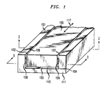
- FIG. 1 A linear slide is shown in pictorial form in FIG. 1.
- An outer member (101) includes a channel defined by the sides 102, 103 and 104 internal to the outer member. Located within the channel is an inner member (105) which translates substantially freely along the rectilinear path defined by the arrow 117.
- the inner member 105 is supported in and guided along the channel by linear bearing mechanisms between the opposite sides 106 and 107 of the inner member 105 and the channel sides 102 and 104. These linear bearing mechanisms are hidden by the covering end plates 111 and 115 attached to the outer member 101 and the inner member 105, respectively.
- the ends of retainers 108 and 109 for the rolling elements are shown between the inner member 105 and the outer member 101.
- FIG. 2 A vertical plane cross section (cross section cut 2 in FIG. 1) of this linear slide is shown in FIG. 2.
- First and second linear bearing mechanisms are located on opposite sides of the linear slide.
- the left linear bearing mechanism is conventional and includes bearing ways (rod pairs 121-122 and 123-124) in secondary channels 133 and 134, respectively, located in the channel wail 102 of the outer member and the side 106 of the inner member. These bearing ways or rods control the travel path of the rolling elements 130 running between the pair of bearing ways.
- a retainer 108 keeps the rolling elements equally spaced along the bearing ways 121-122 and 123-124.
- the right linear bearing mechanism has one of its bearing ways (rod pair 125-126) in a secondary channel 135 in the side 107 of the inner member 105.
- the other bearing way (rod pair 127-128) is contiguous with a preloading bar 141 which is positioned in a secondary channel opening 145 in the side 104 of the primary channel in the outer member 101.
- a longitudinal spring 151 typically having a wave or substantially sinusoidal longitudinal contour, is positioned between the base of the secondary channel opening 145 and the preloading bar 141. The spring 151 applies compressive force against the preloading bar 141 which in turn applies force to the linear bearing mechanisms through the bearing way formed by rod pair 127-128.
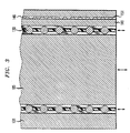
- FIG. 3 A horizontal cross section (cross section cut 3 in FIG. 1) of the linear slide is shown in FIG. 3.
- the inner member 105 is seen positioned in the primary channel of the outer member 101.
- the longitudinal spring 151 is shown located between the preloading bar 141 and the base 146 of the secondary channel so that alternate peaks of its typically sinusoidal or undulating contour are contiguous to the preloading bar 141 and secondary channel base 146.
- the spring applies a compressive force to the preloading bar to keep the linear slide in proper adjustment by eliminating backlash and providing a preload to the linear bearing mechanisms.
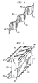
- the longitudinal spring is shown in pictorial form in FIG. 4.
- This spring 151 typically has a sinusoidal or undulating shape with alternating peaks 152 and 153 distributed longitudinally along the length of the spring.
- This spring is constructed of a resilient material with a relatively high modulus of elasticity, such as spring steel. The alternating peaks apply force to the secondary channel base and to the preloading bar as shown in FIGS. 2 and 3 to keep the linear bearing mechanisms in proper adjustment.
- Longitudinal springs that can be used for this purpose are available commercially from the Smalley Steel Ring Company of Wheeling, Ill.
- the preloading bar is shown in pictorial form in FIG. 5.
- the preloading bar 141 includes a shallow channel 142 with a base surface 143 to accept forces from the peaks of the spring and side walls 144 and 145 to control positioning of the spring.
- a longitudinal pedestal 148 is included to reduce the rotational compliance of the preloading bar relative to the outer member.
- the bearing way comprised of rods 127 and 128 is contiguous with the planar surface 147 of the preloading bar.
Landscapes
- Engineering & Computer Science (AREA)
- General Engineering & Computer Science (AREA)
- Mechanical Engineering (AREA)
- Bearings For Parts Moving Linearly (AREA)
- Support Of The Bearing (AREA)
Description
- This invention relates to linear slides and in particular to a mechanism for preloading the linear bearings and thereby relaxing the required tolerances of an outer member, bearing components and an inner member, concurrently reducing the backlash in the linear slide. This avoids the manual adjustments otherwise needed to compensate for dimensional variation and installation conditions.
- Linear slides are widely used to allow linear translational motion between members of mechanisms. These linear slides typically include adjustment elements for controlling clearances between the inner member and its guides. The adjustment elements are often used to apply a preload force to eliminate backlash and reduce compliance perpendicular to the direction of articulation. In the majority of these arrangements, compressive loading of the bearing elements between the outer member and inner member is provided by manual adjustment.
- It is desirable to eliminate the need for manual adjustment in applications where the linear slides are not readily accessible or where frequent adjustment would otherwise be required due to the wear of constant use. Manual adjustment has the disadvantage that the adjustments may not be uniform in application or may be too tight or too loose. Manual adjustment has the additional disadvantage of being labor intensive and therefore expensive. Even a linear slide that is properly adjusted when free standing can, when installed, become too loose or become too tight to the point of binding, depending on the exact interface conditions of the installation.
- One previous arrangement, disclosed in U. S. Patent 3,145,065, provides a compensating mechanism to prevent loss of accuracy in a rectilinear bearing assembly using balls and radially compliant longitudinal rods to support and guide the inner member within the outer member. The longitudinal rods are comprised of tubular members having a relatively large modulus of elasticity and a relatively high yield point. These tubular members are meant to compensate for loose tolerances in the ball assembly.
- Another arrangement, disclosed in U.S. Patent 2,028,718, provides ball races formed by elastic steel bands in order to form a dust proof bearing. These steel bands are meant to reduce the need for accuracy in manufacture of the bearing since these bands tend to compensate for ball expansion.
- A slide bearing support mechanism having one member slidable in a given direction relative to another member and including a pair of parallel slide bearing assemblies disposed between the members is disclosed in the generic U.S. patent 4,923,311. Each bearing assembly provides a raceway defining a travel path in the given direction; an elongated retainer disposed in the raceway; and a plurality of rollers disposed in the retainer and supported by the raceway which guides movement of the rollers along the travel path. Included is a loading mechanism located between the raceways and the rollers for applying loading forces directed transverse to the travel path. The loading mechanism comprising resilient means is retained under compression between one of the members and at least one of the raceways. The resilient loading mechanism efficiently provides a desired preload for the bearing assemblies. The raceways include surfaces formed by longitudinally extending grooves in the side of each bifurcation face and opposed longitudinally extending grooves in the sides of the other member with the rectangular grooves forming an elongated four cornered rectangular chamber and an elongated rectilinear rod positioned in each corner of the chamber.
- These priorly disclosed mechanisms do not however provide a broad range of compensation such as would be needed to provide a high degree of accuracy without the need for manual adjustment or periodic re-adjustment.
- According to the present invention, there is provided a slide as defined in claim 1.
- A linear slide embodying the principles of the invention comprises an outer member, an inner member, first and second linear bearing mechanisms, a preloading bar and a longitudinal spring. The outer member has a primary channel opening for accepting an inner member, and two secondary channels, one in each side of the primary channel, for accepting linear bearing mechanisms. The inner member is located in the primary channel opening. First and second linear bearing mechanisms are located in the secondary channels. These linear bearing mechanisms support and guide the inner member in the primary channel opening in the outer member. The first linear bearing mechanism is conventionally constructed; it can consist of sliding elements or a plurality of rolling elements between two bearing ways, and resides in one of the secondary channels. The second linear bearing mechanism is in the other secondary channel. The preloading bar is contiguous with the second linear bearing mechanism along its entire length. The longitudinal spring is contiguous with the preloading bar on one side and the outer member on the other side. This longitudinal spring is used to provide a compressive force to the preloading bar to eliminate backlash and provide a predictable preload to the linear bearing mechanisms.
- In the drawing:
- FIG. 1 is a pictorial view of a linear slide embodying the principles of the invention;
- FIG. 2 is an end view of a linear slide having linear bearing mechanisms in accord with the invention, shown with its end plates removed;
- FIG. 3 is a plan view of a linear slide having linear bearing mechanisms in accord with the invention;
- FIG. 4 is a pictorial schematic of a longitudinal spring used in the linear slide disclosed in FIGS. 1 and 2; and
- FIG. 5 is a pictorial view of a preloading bar used in the linear slide disclosed in FIGS. 1 and 2.
- A linear slide is shown in pictorial form in FIG. 1. An outer member (101) includes a channel defined by the
sides arrow 117. Theinner member 105 is supported in and guided along the channel by linear bearing mechanisms between theopposite sides inner member 105 and thechannel sides covering end plates outer member 101 and theinner member 105, respectively. The ends ofretainers inner member 105 and theouter member 101. - A vertical plane cross section (
cross section cut 2 in FIG. 1) of this linear slide is shown in FIG. 2. First and second linear bearing mechanisms are located on opposite sides of the linear slide. The left linear bearing mechanism is conventional and includes bearing ways (rod pairs 121-122 and 123-124) insecondary channels channel wail 102 of the outer member and theside 106 of the inner member. These bearing ways or rods control the travel path of therolling elements 130 running between the pair of bearing ways. Aretainer 108 keeps the rolling elements equally spaced along the bearing ways 121-122 and 123-124. - The right linear bearing mechanism has one of its bearing ways (rod pair 125-126) in a
secondary channel 135 in theside 107 of theinner member 105. The other bearing way (rod pair 127-128) is contiguous with apreloading bar 141 which is positioned in a secondary channel opening 145 in theside 104 of the primary channel in theouter member 101. Alongitudinal spring 151, typically having a wave or substantially sinusoidal longitudinal contour, is positioned between the base of the secondary channel opening 145 and thepreloading bar 141. Thespring 151 applies compressive force against the preloadingbar 141 which in turn applies force to the linear bearing mechanisms through the bearing way formed by rod pair 127-128. - A horizontal cross section (
cross section cut 3 in FIG. 1) of the linear slide is shown in FIG. 3. Theinner member 105 is seen positioned in the primary channel of theouter member 101. Thelongitudinal spring 151 is shown located between thepreloading bar 141 and thebase 146 of the secondary channel so that alternate peaks of its typically sinusoidal or undulating contour are contiguous to the preloadingbar 141 andsecondary channel base 146. The spring applies a compressive force to the preloading bar to keep the linear slide in proper adjustment by eliminating backlash and providing a preload to the linear bearing mechanisms. - The longitudinal spring is shown in pictorial form in FIG. 4. This
spring 151 typically has a sinusoidal or undulating shape withalternating peaks - The preloading bar is shown in pictorial form in FIG. 5. The preloading
bar 141 includes ashallow channel 142 with abase surface 143 to accept forces from the peaks of the spring andside walls longitudinal pedestal 148 is included to reduce the rotational compliance of the preloading bar relative to the outer member. The bearing way comprised ofrods planar surface 147 of the preloading bar.
Claims (1)
- A linear slide for a rectilinear motion device;
comprising:
an outer member (101) having a primary channel (102, 103 and 104) and an inner member (105) located within the primary channel;
first and second linear bearing mechanisms (121, 122, 123, 124, 125, 126, 127, and 128) on opposing sidewalls (102, 104) of the primary channel to support and guide the inner member;
a preloading bar (141) contiguous with the second linear bearing mechanism;
a longitudinal spring (151) having a substantially longitudinal sinusoidal contour and being extended longitudinally along the second linear bearing mechanism and located adjacent an inner surface of the outer member and positioned for applying a compressive force against the preloading bar;
the outer member including a secondary longitudinal channel (145) in the wall adjacent to the second linear mechanism into which the preloading bar and the longitudinal spring are inserted with the spring fitted between the base of the longitudinal channel and the preloading bar; and
CHARACTERIZED BY:
the preloading bar including a longitudinal groove (142) for accepting and positionally constraining the adjacent spring and a longitudinal pedestal (148) extending along the length of the preloading bar and in contact with a base surface (146) of the secondary longitudinal channel to supply a force operative to reduce rotational compliance of the preloading bar relative to the outer member.
Applications Claiming Priority (2)
| Application Number | Priority Date | Filing Date | Title |
|---|---|---|---|
| US76251591A | 1991-09-18 | 1991-09-18 | |
| US762515 | 1991-09-18 |
Publications (2)
| Publication Number | Publication Date |
|---|---|
| EP0533399A1 EP0533399A1 (en) | 1993-03-24 |
| EP0533399B1 true EP0533399B1 (en) | 1995-12-06 |
Family
ID=25065288
Family Applications (1)
| Application Number | Title | Priority Date | Filing Date |
|---|---|---|---|
| EP92308226A Expired - Lifetime EP0533399B1 (en) | 1991-09-18 | 1992-09-10 | Mechanism for preloading linear bearing slides |
Country Status (5)
| Country | Link |
|---|---|
| EP (1) | EP0533399B1 (en) |
| JP (1) | JPH05215131A (en) |
| KR (1) | KR100258670B1 (en) |
| DE (1) | DE69206549T2 (en) |
| TW (1) | TW205587B (en) |
Families Citing this family (9)
| Publication number | Priority date | Publication date | Assignee | Title |
|---|---|---|---|---|
| US5658081A (en) * | 1995-12-11 | 1997-08-19 | Industrial Technology Research Institute | Adjusting mechanism for a prestressed bearing arrangement |
| DE19915417C2 (en) * | 1998-04-04 | 2001-07-19 | Gkn Automotive Gmbh | Tripod joint with elastic means |
| JP2002349564A (en) * | 2001-05-31 | 2002-12-04 | Thk Co Ltd | Track rail mounting structure of linear guide device |
| DE10340672B4 (en) * | 2003-09-04 | 2011-04-28 | Ab Skf | linear guide |
| JP4587103B2 (en) | 2005-04-19 | 2010-11-24 | Smc株式会社 | Cylinder device guide mechanism |
| EP2183493B1 (en) | 2007-08-25 | 2015-06-17 | Accuride International GmbH | Linear guidance system |
| JP5412432B2 (en) | 2007-08-25 | 2014-02-12 | アクライド インターナショナル ゲーエムベーハー | Linear guide system with hollow rail |
| DE202019100666U1 (en) * | 2019-02-05 | 2020-05-08 | Igus Gmbh | Sliding element |
| KR102024135B1 (en) * | 2019-05-30 | 2019-09-23 | 주식회사 서형 | Linear motion guide apparatus |
Family Cites Families (1)
| Publication number | Priority date | Publication date | Assignee | Title |
|---|---|---|---|---|
| US4923311A (en) * | 1989-02-28 | 1990-05-08 | Gibbs Henry L | Preloaded slide bearing support apparatus |
-
1992
- 1992-07-08 TW TW081105417A patent/TW205587B/zh active
- 1992-09-10 EP EP92308226A patent/EP0533399B1/en not_active Expired - Lifetime
- 1992-09-10 DE DE69206549T patent/DE69206549T2/en not_active Expired - Fee Related
- 1992-09-14 KR KR1019920016636A patent/KR100258670B1/en not_active IP Right Cessation
- 1992-09-16 JP JP4245375A patent/JPH05215131A/en not_active Withdrawn
Also Published As
| Publication number | Publication date |
|---|---|
| DE69206549T2 (en) | 1996-04-25 |
| KR930006342A (en) | 1993-04-21 |
| KR100258670B1 (en) | 2000-06-15 |
| JPH05215131A (en) | 1993-08-24 |
| DE69206549D1 (en) | 1996-01-18 |
| EP0533399A1 (en) | 1993-03-24 |
| TW205587B (en) | 1993-05-11 |
Similar Documents
| Publication | Publication Date | Title |
|---|---|---|
| US5201584A (en) | Mechanism for preloading linear bearing slides | |
| US4923311A (en) | Preloaded slide bearing support apparatus | |
| EP0533399B1 (en) | Mechanism for preloading linear bearing slides | |
| US3113807A (en) | Ball slide | |
| EP1328734B1 (en) | Linear motion bearing segment | |
| US6476525B2 (en) | Linear actuator | |
| US5487609A (en) | Slide unit for linear motion | |
| US6149308A (en) | Linear rail system having preload adjustment apparatus | |
| JP2004522099A (en) | Linear guide | |
| KR102244969B1 (en) | Direct-acting guide device and method of manufacturing direct-acting guide device | |
| US5829885A (en) | Shaft supported linear motion guide system | |
| US8100025B2 (en) | Rolling element retainer | |
| JPH07190056A (en) | Track rail mounting structure in direct-acting unit | |
| US4616885A (en) | Dust-free rolling-contact bearing assembly | |
| US7401978B2 (en) | Linear motion guiding apparatus | |
| JPH07124831A (en) | Linear guide device | |
| EP1403541B1 (en) | Linear rolling element bearing with rollers retained in a flexible cage | |
| US6109789A (en) | Linear slide | |
| JP3434369B2 (en) | Rodless cylinder | |
| TW202304348A (en) | Slide rail unit | |
| US5897213A (en) | Slide assembly for preloading roller bearings | |
| US11767882B2 (en) | Motion guide apparatus | |
| KR890000318B1 (en) | Roller bearing for linear motion | |
| US4655612A (en) | Bearing adjustment apparatus | |
| US11542983B2 (en) | Motion guide device |
Legal Events
| Date | Code | Title | Description |
|---|---|---|---|
| PUAI | Public reference made under article 153(3) epc to a published international application that has entered the european phase |
Free format text: ORIGINAL CODE: 0009012 |
|
| AK | Designated contracting states |
Kind code of ref document: A1 Designated state(s): DE FR GB IT NL |
|
| RIN1 | Information on inventor provided before grant (corrected) |
Inventor name: SIMONS, EVERETT FURBER |
|
| 17P | Request for examination filed |
Effective date: 19930909 |
|
| 17Q | First examination report despatched |
Effective date: 19940303 |
|
| RAP3 | Party data changed (applicant data changed or rights of an application transferred) |
Owner name: AT&T CORP. |
|
| GRAA | (expected) grant |
Free format text: ORIGINAL CODE: 0009210 |
|
| AK | Designated contracting states |
Kind code of ref document: B1 Designated state(s): DE FR GB IT NL |
|
| ITF | It: translation for a ep patent filed | ||
| ET | Fr: translation filed | ||
| REF | Corresponds to: |
Ref document number: 69206549 Country of ref document: DE Date of ref document: 19960118 |
|
| PLBE | No opposition filed within time limit |
Free format text: ORIGINAL CODE: 0009261 |
|
| STAA | Information on the status of an ep patent application or granted ep patent |
Free format text: STATUS: NO OPPOSITION FILED WITHIN TIME LIMIT |
|
| 26N | No opposition filed | ||
| REG | Reference to a national code |
Ref country code: GB Ref legal event code: IF02 |
|
| PGFP | Annual fee paid to national office [announced via postgrant information from national office to epo] |
Ref country code: FR Payment date: 20050823 Year of fee payment: 14 |
|
| PGFP | Annual fee paid to national office [announced via postgrant information from national office to epo] |
Ref country code: NL Payment date: 20050904 Year of fee payment: 14 |
|
| PGFP | Annual fee paid to national office [announced via postgrant information from national office to epo] |
Ref country code: GB Payment date: 20050907 Year of fee payment: 14 |
|
| PGFP | Annual fee paid to national office [announced via postgrant information from national office to epo] |
Ref country code: DE Payment date: 20050909 Year of fee payment: 14 |
|
| PGFP | Annual fee paid to national office [announced via postgrant information from national office to epo] |
Ref country code: IT Payment date: 20060930 Year of fee payment: 15 |
|
| PG25 | Lapsed in a contracting state [announced via postgrant information from national office to epo] |
Ref country code: NL Free format text: LAPSE BECAUSE OF NON-PAYMENT OF DUE FEES Effective date: 20070401 |
|
| PG25 | Lapsed in a contracting state [announced via postgrant information from national office to epo] |
Ref country code: DE Free format text: LAPSE BECAUSE OF NON-PAYMENT OF DUE FEES Effective date: 20070403 |
|
| GBPC | Gb: european patent ceased through non-payment of renewal fee |
Effective date: 20060910 |
|
| NLV4 | Nl: lapsed or anulled due to non-payment of the annual fee |
Effective date: 20070401 |
|
| REG | Reference to a national code |
Ref country code: FR Ref legal event code: ST Effective date: 20070531 |
|
| PG25 | Lapsed in a contracting state [announced via postgrant information from national office to epo] |
Ref country code: GB Free format text: LAPSE BECAUSE OF NON-PAYMENT OF DUE FEES Effective date: 20060910 |
|
| PG25 | Lapsed in a contracting state [announced via postgrant information from national office to epo] |
Ref country code: FR Free format text: LAPSE BECAUSE OF NON-PAYMENT OF DUE FEES Effective date: 20061002 |
|
| PG25 | Lapsed in a contracting state [announced via postgrant information from national office to epo] |
Ref country code: IT Free format text: LAPSE BECAUSE OF NON-PAYMENT OF DUE FEES Effective date: 20070910 |