EP0532318B1 - Sheet stacking apparatus - Google Patents
Sheet stacking apparatus Download PDFInfo
- Publication number
- EP0532318B1 EP0532318B1 EP92308234A EP92308234A EP0532318B1 EP 0532318 B1 EP0532318 B1 EP 0532318B1 EP 92308234 A EP92308234 A EP 92308234A EP 92308234 A EP92308234 A EP 92308234A EP 0532318 B1 EP0532318 B1 EP 0532318B1
- Authority
- EP
- European Patent Office
- Prior art keywords
- container
- pallet
- sheet
- sheets
- elevator
- Prior art date
- Legal status (The legal status is an assumption and is not a legal conclusion. Google has not performed a legal analysis and makes no representation as to the accuracy of the status listed.)
- Expired - Lifetime
Links
Images


Classifications
-
- B—PERFORMING OPERATIONS; TRANSPORTING
- B65—CONVEYING; PACKING; STORING; HANDLING THIN OR FILAMENTARY MATERIAL
- B65H—HANDLING THIN OR FILAMENTARY MATERIAL, e.g. SHEETS, WEBS, CABLES
- B65H31/00—Pile receivers
- B65H31/20—Pile receivers adjustable for different article sizes
-
- B—PERFORMING OPERATIONS; TRANSPORTING
- B65—CONVEYING; PACKING; STORING; HANDLING THIN OR FILAMENTARY MATERIAL
- B65H—HANDLING THIN OR FILAMENTARY MATERIAL, e.g. SHEETS, WEBS, CABLES
- B65H31/00—Pile receivers
- B65H31/04—Pile receivers with movable end support arranged to recede as pile accumulates
- B65H31/08—Pile receivers with movable end support arranged to recede as pile accumulates the articles being piled one above another
- B65H31/10—Pile receivers with movable end support arranged to recede as pile accumulates the articles being piled one above another and applied at the top of the pile
-
- B—PERFORMING OPERATIONS; TRANSPORTING
- B65—CONVEYING; PACKING; STORING; HANDLING THIN OR FILAMENTARY MATERIAL
- B65H—HANDLING THIN OR FILAMENTARY MATERIAL, e.g. SHEETS, WEBS, CABLES
- B65H2801/00—Application field
- B65H2801/03—Image reproduction devices
- B65H2801/06—Office-type machines, e.g. photocopiers
Definitions
- This invention relates generally to an electrophotographic printing machine, and more particularly concerns an apparatus for stacking sets of copy sheets.
- US-A-3,747,920 discloses a sheet unloading apparatus used in conjunction with a punch press.
- a trolley moves material from a loading position to an unloading position.
- a support table receives sheets from the trolley and is vertically movable by a motor operated scissors type of support.
- US-A-4,359,218 describes a sheet collection and discharge system. Sheets continuously accumulate at a stacker station.
- a table supported for vertical movement on scissor type collapsible legs receives the sheets. The lower ends of the legs have rollers for transversing the apparatus across linear tracks.
- the table has a base platform element, the under surface of which is formed with connection pieces to which the upper ends of the support legs are attached.
- a series of spaced apart columns extend vertically from the upper surface of the table platform. Each column is generally rectangular with a longitudinal axis parallel to the longitudinal axis of the apparatus. The upper surfaces of the columns support the stack of sheets at the stacker station.
- the belt conveyors discharge sheets in a batch onto a discharge table surface after the upper carrying surfaces of the table have descended beneath the level of the conveyor belts.
- a multi-mode sheet stacker apparatus for stacking a wide variety of sheet sizes fed thereto by a feeder means, comprising: a main pallet; a container; a container pallet positioned within said container onto which sheets are placed by the feeder means; and elevator means for lifting said container pallet into position to receive sheets from said feeder means; characterised in that the container is positioned on said main pallet, and in that the apparatus is operable in a first mode of operation wherein with said container removed from the stacker apparatus, said main pallet is moved into a sheet receiving position, and in a second mode of operation wherein said elevator means when actuated lifts only said container pallet and not said main pallet.
- a printer having a sheet stacking apparatus that is capable of stacking sets of a wide variety of copy sheet sizes and weights.
- the sheet stacking apparatus includes an elevator system and a main pallet adapted for ascending and descending movement by the elevator system.
- copy sheets can be stacked directly on the main pallet and at the end of a run the main pallet can be withdrawn from the printer.
- a container that includes a container pallet is provided for placement on the main pallet for receipt of copy sheets in a second mode of operation, and in a third mode of operation copy sheets are stacked on the container pallet without the container.
- a spider latch connected to the main pallet is rotated in order to allow a lift frame to pass through the main pallet and lift the container pallet.
- the container includes a two corner structure that enhances the sheet stacking apparatus by providing copy sheet set at a time removal by way of one of open areas of the structure instead of having to lift the copy sheet set over the top of the container.
- the sheet stacking apparatus includes means for stacking flimsy, light weight, low beam strength sheets in the form of a plurality of belts entrained around a drive roll and two idler rolls.
- the belts are positioned so that they are contacted by a sheet while the sheets are being driven by input nips and a sheet invertion disc. After the trail edge of the sheet exits the input nips, the belts un-roll the sheet for stacking purposes.
- FIG. 1 schematically depicts an electrophotographic printing machine incorporating the features of the present invention therein. It will become evident from the following discussion that the sheet stacking apparatus of the present invention may be employed in a wide variety of devices and is not specifically limited in its application to the particular embodiments depicted herein.
- FIGS. 1 and 2 illustrate a feeder/stacker 10 which includes two sheet stackers 20 according to the present invention.
- Feeder portion 12 can be, for example, a conventional high speed copier or pri nter.
- One type of system usable as feeder portion 12 can include an optical scanner for digitizing data contained on original documents and supplying the digitized data to a high speed, high quality printer such as a laser printer which outputs documents to the sheet stackers 20.
- Each sheet stacker 20 includes a rotating disk 21 which includes one or more slots for receiving sheets therein. Rotating disk 21 then rotates to invert the sheet and register the leading edge of the sheet against a registration means or wall 23 which strips the sheet from the rotatable disk 21.
- Elevator platform 30 is moved in a vertical direction by the actuation of a screw drive mechanism 40.
- the screw drive mechanism includes a separate, vertical, rotatable shaft having a threaded outer surface at each corner of the elevator platform and extending through a threaded aperture therein (four vertical shafts in total). As the vertical shafts 42 - 45 are rotated by motor, platform 30 is raised or lowered.
- a stack height sensor 27, described below, is used to control the movement of platform 30 so that the top of the stack remains at substantially the same level.
- Each stacker 20 also includes a tamping mechanism (not shown) which is capable of offsetting sets of sheets in a direction perpendicular to the process direction.
- the provision of more than one disk stacker 20 enables sheets to be outputted at higher speeds and in a continuous fashion.
- a specific requirement of the high speed computer printer market is the ability to provide long run capability with very minimal down time due to system failures, lack of paper supply, or lost time during unload.
- the outputting of documents need not be interrupted when one of the stackers becomes full since documents can merely be fed to the other stacker while the full stacker is unloaded. Thus, should one stacker become filled or break down, the outputting of copy sheets is not interrupted.
- each stacker enables both stackers to be bypassed so that documents can be fed to other downstream devices such as additional stackers or sheet finishing apparatus, such as, for example, folding or stapling devices.
- a trail edge guide 28 is positioned and movably mounted so that sheets having different lengths can be accommodated in sheet stacker 20.
- FIG. 2 illustrates the position of trail edge guide 28 for smaller sheets such as sheets (long edge fed).
- the position of trail edge guide 28′ is shown for sheets that are 216 x 432mm (short edge fed).
- the sheets Before entering sheet stacker 20, the sheets exit through output nip 24 of an upstream device.
- the upstream device could be a printer, copier, other disk stacker, or a device for rotating sheets. Sheets may need to be rotated so that they have a certain orientation after being inverted by disk 21.
- the sheets can enter disk stacker 20 long edge first or short edge first.
- the sheet After entering stacker 20, the sheet enters predisk transport 22 where the sheet is engaged by the nip formed between one or more pairs of disk stacker input rollers 25. If a bypass signal is provided, bypass deflector gate 26 moves downward to deflect the sheet into bypass transport assembly 86. If no bypass signal is provided, the sheet is directed to disk input rollers 90 which constitute part of the feeding means for feeding sheets to an input position of disk 21.
- the movement of the disk 21 can be controller by a variety of means conventional in the art.
- a sensor located upstream of disk 21 detects the presence of a sheet approaching disk 21. Since disk input nip 90 operates at a constant first velocity, the time required for the lead edge of the sheet to reach the disk slot is known. As the lead edge of the sheet begins to enter the slot, the disk rotates through a 180° cycle. The disk 21 is rotated at a peripheral velocity which is about 1/2 the velocity of input rollers 25 so that the leading edge of the sheet progressively enters the disk slot. However, the disk 21 is rotated at an appropriate speed so that the leading edge of the sheet contacts registration wall 23 prior to contacting the end of the slot. This reduces the possibility of damage to the lead edge of the sheet. Such a manner of control is disclosed in US-A-4,431,177.
- trail edge transport belt 80 One advantageous feature of the illustrated apparatus involves the construction and operation of trail edge transport belt 80.
- the present apparatus includes a trail edge assist belt or belts 80 which are rotated at a velocity which is greater than the velocity at which feeding means (which includes input nips 24 and 25) is operated.
- transport belt 80 is rotated at a velocity which is 1.5 times the velocity of the feeding means.
- trail edge transport belt 80 is arranged at an angle to elevator platform 30 so that a distance between a portion of the transport belt and elevator platform 30 decreases as the transport belt 80 extends away from rotatable disk 21.
- Three pulleys 81, 82, and 83 at least one of which is driven by a motor (not shown) maintain tension on transport belt 80 and cause transport belt 80 to rotate at a velocity which is greater than that of the feeder means.
- Transport belt 80 is configured and positioned with respect to disk 21 to ensure that all sheets including lightweight sheets begin to make contact with the belt 80 while each sheet is being driven by input nip 25. After the trail edge exits the input nip 25, the sheet's velocity will be in the direction required to un-roll the sheet. The sheet will thus un-roll, forcing it to not sag away from the transport belt, increasing the reliability of the stacker.
- belt 80 such that a section 80′ thereof is closely spaced with respect to disk 21 and slopes downwardly at a steep angle in a span between rollers 81 and 82 as it extends away from disk 21.
- This configuration facilitates control for the sheet in that the sheet contacts the belt while it is still in input rollers 90.
- a second portion 80 ⁇ of belt 80 is parallel to the top surface of elevator 30 while a third portion of the belt 80 ⁇ ′ is at an acute angle with respect to elevator 30 that is less than the acute angle of slope 80'.
- Belt 80 is configured as an inverted triangle with the apex 82 of the triangle being downstream from disk 21 and positioned below a plane across the uppermost portion of the disk. A portion of the belt most remote from the disk is an uninterrupted straight span that is angled downwardly with respect to a horizontal plane.
- Elevator 30 has projections 32 and 31 therein that are configured to fit into openings 53 and 54 of main pallet 50 as well as openings 61 and 62 in spider latch 60.
- the spider latch is in the unactuated position as shown in dotted lines in FIG. 3A, and indicated by pointer 63, the projections 32 and 31 of elevator 30 engage the underside of spider latch 60 at positions offset from openings 61 and 62 so that the elevator 30 can raise the main pallet 50.
- Portions 66 and 67 of spider latch 60 are also used to raise the pallet, being contacted by arms 37 and 38 of the elevator 30.
- a conventional photosensor 27 that includes an emitter and receiver monitors the sheet stack height and through signals to a controller in printer 12, indexes the pallet downward in response to the receiver being blocked by the top of the sheet stack.
- elevator 30 has tray or pallet 50, as shown separately in FIG. 6, mounted thereabove for the support of copy sheets.
- drive motor 41 is a bi-directional 115 Volt AC motor that raises and lowers elevator 30. A 100 millisecond delay is required before reversing the motor direction.
- the motor capacitor ensures that the motor starts and runs in the correct direction.
- the motor contains an internal sensor. If the motor becomes too hot, the sensor switches off the motor. The thermal sensor resets automatically when the motor cools.
- the motor 41 is switched ON in order to raise or lower elevator 30, the elevator 30 is moved by a drive belt 46.
- One drive belt 46 connects the drive from motor 41 to the four lead screws 42 - 45.
- a spring (not shown) attached to the motor and frame applies tension to the drive belt.
- Elevator 30 is connected to the four lead screws by lift nuts (not shown).
- Two triacs mounted on a remote board are associated with the motor. One triac is used to raise elevator 30 with the other being required to lower elevator 30.
- the control logic sends a 5 volt signal to the triac.
- the triac then sends AC power to the motor 41 and capacitor and switches ON motor 41 for a predetermined number of milliseconds. Afterwards, the control logic switches off the 5 volt signal to the triac so as to de-energize motor 41.
- the pitch of the lead screws is selected so that the predetermined millisecond rotation of the lead screws will translate elevator 30 a fixed preselected distance in millimeters.
- a container pallet 58 (FIGS 5A and 8) is placed on top of main pallet 50.
- Container pallet 58 has projections on the bottom thereof that mate with complimentary openings 68 in main pallet 50. Placing of container pallet 58 onto main pallet 50 will cause the weight of container pallet 58 to actuate spider latch 60 by pressing it out of engagement with ramp 64. Once this happens, spring 65 pulls the spider latch to the dotted line position shown in FIG. 5A and indicated by pointer 63.
- elevator 30 With the spider latch in this actuated position, elevator 30 will lift the container pallet 58 into position to receive sheets, rather than the main pallet 50, because the projections 32 and 31 will now pass through openings 53 and 54 of the main pallet 50, and through openings 61 and 62 in the spider latch 60, to contact the underside of container pallet 58 and lift it. Similarly, arms 37 and 38 of the elevator 30 will pass through openings 35 and 36 of the main pallet 50. The stacker is emptied by lifting the container pallet off the main pallet. Container pallets are sized according to the size of sheets to be stacked and projections on the bottom of the container pallets fit into those of the openings in the main pallet as appropriate.
- FIG. 4, 7 and 8 The preferred embodiment of the present invention is shown in FIG. 4, 7 and 8 that includes containers 70 and 70′ in position to receive sheets for stacking.
- Container 70 is sized to receive 216 x 279mm sheets while dotted line container 70′ is sized to receive 216 x 432 mm sheets.
- Containers are sized to accommodate sheet sizes from B5 to A3 and each size will fit onto main pallet 50.
- Each container has a container pallet 58 therein that is lifted to a stack loading position by elevator 30.
- Each container has magnets attached to one surface thereof that are used to signal the printer's controller as to the size of containers in place.
- Main pallet 50 and container pallet 58 also have magnets 79 attached thereto that signal the controller while the apparatus is being used as a sheet stack support.
- Container 70 is shown in its unloaded position in FIG. 4 and in position to receive sheets in FIG 5 with container pallet 58 in a raised position.
- container 70 may include a container pallet and has a support surface with relieved areas and only two diametrically opposite corners which provide the advantages over four corner containers of: (1) allowing multiple size containers to be used with the same elevator lift mechanism; (2) allowing improved visibility from any angle for determining stacking progress within the printer by checking the status of the containers (full or empty) outside the printer; (3) providing a symmetrical (identical) corner design which allows one mold for both corners and is common for all container sizes; (4) allowing for improved container nesting for storage and shipping; (5) providing separate container floor and corners which allow dismantled shipment for improved nesting; (6) allowing for set removal via an open corner instead of lifting copy sheets over the top of the container thereby improving overall operability; and (7) allowing access to lift the entire stack of sheets from the container without the use of an unload pedestal as heretofore required.
- Container 70 in FIGS. 7 and 8 in order to meet the heretofore mentioned advantages comprises a base support member 75 that has two relieved or cut-away portions 76 and 77 therein leaving only two right angled corners that are opposite each other.
- Upstanding side members 71, 72, 73 and 74 are connected to the two corners of the base member to allow several reams of copy sheets to be stacked on container pallet 58 which is positioned on base member 75.
- Each container size, i.e., for 216 x 279mm, 216x 432mm, etc. is oversized by about 12mm in order for each copy sheet set including tab stock within the container walls to be offset by conventional side joggers.
- Sides 71, 72, 73 and 74 each slope downwardly and outwardly from top to bottom to provide open viewing of sheets in the container.
- container 70 has projections 78 on the bottom surface thereof that mate with opening 68 in the main pallet and releases latch 60 due to the weight of the container on the main pallet.
- the projections also provide stability and precise, predictable positioning of the container.
- a stacker apparatus that can handle all sizes for sheets and all sizes of containers as opposed to previous stackers that used only one container for multiple sized sheets.
- the present sheet stacker operates in three different modes. In a first mode of operation, sheets are stacked directly on the main pallet. In a second mode of cooperation, sheets are stacked on the container pallet without the container. And in a third mode of operation, sheets are stacked on a container pallet which is positioned within a container with the container being placed onto the main pallet. In either mode of operation the main pallet slides out for unloading and is raised and lowered by an elevator mechanism to facilitate the stacking function.
- the main pallet has a four point lift frame which is used for all sheet stacking directly onto a predetermined pallet. When the container and its pallet are used, a spider latch is rotated to allow the lift frame of the elevator to pass through the main pallet and lift the container pallet.
- copy sheet output from a printer is handled in low cost, removable, plural, interchangeable, multiple job-handling projection, side walls, job stacking containers, with an added false-bottom stacking platform, which stacking platform is automatically disengagable from lifting and stack height control means therefor which are left inside the printer itself.
- the containers allow offset stacking therein, on the lifted false bottom, registered by end and side joggers in the machine, not in the bins, then allows removal of the whole stack of offset jobs in and with the containers, for processing off-line, while another container is being inserted, and the container in the next stacker module is being filled by an automatic switch over of the output to the next module or stack apparatus with no pitch loss.
Landscapes
- Engineering & Computer Science (AREA)
- Mechanical Engineering (AREA)
- Pile Receivers (AREA)
- Paper Feeding For Electrophotography (AREA)
- Sheets, Magazines, And Separation Thereof (AREA)
Description
- This invention relates generally to an electrophotographic printing machine, and more particularly concerns an apparatus for stacking sets of copy sheets.
- In commercial high speed printing machines large volumes of sets of copy sheets are fed onto a stacking tray. When the tray is loaded to its capacity, an elevator moves the tray to a station where an operator can readily remove the sets of copy sheets. Frequently, the printing machine is idling and not producing copy sets while the operator is unloading the previously completed sets from the stacker tray. This reduces the productivity time of the printing machine by increasing its down time. Ideally, high capacity printing machines should be run on a continuous basis and the unloading of copy sets should be such that the operator can simply and easily remove copy sheet sets from one sheet stacking apparatus while a new batch of copy sheet sets are being run into a second sheet stacking device. However, presently, most high speed printers use a single elevator manoeuvred tray for receiving copy sheet sets, which is cumbersome for copy set removal, or use a single container and a pedestal to unlead copy sheet sets, for example, the Xerox® 9700 printer. Also, previous high speed printers handled 216 x 279mm and 216 x 356mm sheets with and without containers. Accordingly, it is desirable for printing machines to have the capability of unloading while running and to be able to handle all sizes of copy sheets and all sizes of containers from B5 to A3 with ease.
- Various approaches have been devised for stacking and unloading sets of copy sheets.
- US-A-3,747,920 discloses a sheet unloading apparatus used in conjunction with a punch press. A trolley moves material from a loading position to an unloading position. A support table receives sheets from the trolley and is vertically movable by a motor operated scissors type of support.
- US-A-4,359,218 describes a sheet collection and discharge system. Sheets continuously accumulate at a stacker station. A table supported for vertical movement on scissor type collapsible legs receives the sheets. The lower ends of the legs have rollers for transversing the apparatus across linear tracks. The table has a base platform element, the under surface of which is formed with connection pieces to which the upper ends of the support legs are attached. A series of spaced apart columns extend vertically from the upper surface of the table platform. Each column is generally rectangular with a longitudinal axis parallel to the longitudinal axis of the apparatus. The upper surfaces of the columns support the stack of sheets at the stacker station. Interspaced between the table carrying columns are a series of lateral belt conveyors driven by a motor through a series of rollers. The belt conveyors discharge sheets in a batch onto a discharge table surface after the upper carrying surfaces of the table have descended beneath the level of the conveyor belts.
- In accordance with one aspect of the present invention, there is provided a multi-mode sheet stacker apparatus for stacking a wide variety of sheet sizes fed thereto by a feeder means, comprising: a main pallet; a container; a container pallet positioned within said container onto which sheets are placed by the feeder means; and elevator means for lifting said container pallet into position to receive sheets from said feeder means; characterised in that the container is positioned on said main pallet, and in that the apparatus is operable in a first mode of operation wherein with said container removed from the stacker apparatus, said main pallet is moved into a sheet receiving position, and in a second mode of operation wherein said elevator means when actuated lifts only said container pallet and not said main pallet.
- Thus, there is provided a printer having a sheet stacking apparatus that is capable of stacking sets of a wide variety of copy sheet sizes and weights. The sheet stacking apparatus includes an elevator system and a main pallet adapted for ascending and descending movement by the elevator system. In a first mode of operations, copy sheets can be stacked directly on the main pallet and at the end of a run the main pallet can be withdrawn from the printer. A container that includes a container pallet is provided for placement on the main pallet for receipt of copy sheets in a second mode of operation, and in a third mode of operation copy sheets are stacked on the container pallet without the container. When the container and its pallet are used, a spider latch connected to the main pallet is rotated in order to allow a lift frame to pass through the main pallet and lift the container pallet.
- In another aspect of the invention, the container includes a two corner structure that enhances the sheet stacking apparatus by providing copy sheet set at a time removal by way of one of open areas of the structure instead of having to lift the copy sheet set over the top of the container.
- In yet another aspect of the invention, the sheet stacking apparatus includes means for stacking flimsy, light weight, low beam strength sheets in the form of a plurality of belts entrained around a drive roll and two idler rolls. The belts are positioned so that they are contacted by a sheet while the sheets are being driven by input nips and a sheet invertion disc. After the trail edge of the sheet exits the input nips, the belts un-roll the sheet for stacking purposes.
- Other aspects of the present invention will become apparent as the following description proceeds and upon reference to the drawings in which:
- FIG. 1 is an isometric view of a printing machine incorporating the sheet stacking apparatus of the present invention.
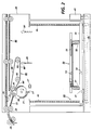
- FIG. 2 is a side view of the sheet stacking apparatus of the present invention showing a main pallet in its home position.
- FIG. 3 is a side view of the sheet stacking apparatus of FIG. 2 with the main pallet in a raised position.
- FIG. 3A is a plan view of the sheet stacking apparatus of FIG. 2 showing a spider latch in phantom in an unactivated position which facilitates movement of the main pallet by an elevator mechanism.
- FIG 4 is a side view of the sheet stacking apparatus of FIG. 2 showing a container for stacking 216 x 279mm sheets in solid lines and a container for 216 x 432mm sheets in dotted lines, both positioned on the main pallet with one showing a container pallet as an insert.
- FIG. 5 is a side view of the sheet stacking apparatus of the present invention showing a container on the main pallet with its container pallet lifted into a sheet stacking position by an elevator mechanism.
- FIG. 5A is a plan view of the sheet stacking apparatus of FIG. 5 showing the spider latch mechanism in its actuated position in phantom which allows the elevator mechanism to lift the container pallet.
- FIG. 6 is a schematic isometric view of the main pallet of the sheet stacking apparatus of FIG. 2.
- FIG. 7 is a schematic isometric view of a container mounted on the main pallet of FIG. 6.
- FIG. 8 is a schematic isometric view of a container and container pallet for 216 x 279mm sheets mounted on the main pallet.
- FIG. 9 is a partial schematic isometric view of the container in FIG. 5 showing projections on its bottom surface that mate with complimentary openings in the main pallet.
- For a general understanding of the features of the present invention, reference is made to the drawings. In the drawings, like reference numerals have been used throughout to identify identical elements, FIG. 1 schematically depicts an electrophotographic printing machine incorporating the features of the present invention therein. It will become evident from the following discussion that the sheet stacking apparatus of the present invention may be employed in a wide variety of devices and is not specifically limited in its application to the particular embodiments depicted herein.
- FIGS. 1 and 2 illustrate a feeder/
stacker 10 which includes twosheet stackers 20 according to the present invention.Feeder portion 12 can be, for example, a conventional high speed copier or pri nter. One type of system usable asfeeder portion 12 can include an optical scanner for digitizing data contained on original documents and supplying the digitized data to a high speed, high quality printer such as a laser printer which outputs documents to thesheet stackers 20. Eachsheet stacker 20 includes arotating disk 21 which includes one or more slots for receiving sheets therein. Rotatingdisk 21 then rotates to invert the sheet and register the leading edge of the sheet against a registration means orwall 23 which strips the sheet from therotatable disk 21. The sheet then drops to the top of the stack of inverted sheets which are supported on either amain pallet 50 or container pallet 58 (FIG. 4), both of which are vertically movable byelevator 30. An overhead trail edgeassist belt system 80, to be described in more detail below, is located adjacent therotatable disk 21 and aboveelevator platform 30 to assist in the inversion of sheets.Elevator platform 30 is moved in a vertical direction by the actuation of ascrew drive mechanism 40. The screw drive mechanism includes a separate, vertical, rotatable shaft having a threaded outer surface at each corner of the elevator platform and extending through a threaded aperture therein (four vertical shafts in total). As the vertical shafts 42 - 45 are rotated by motor,platform 30 is raised or lowered. Astack height sensor 27, described below, is used to control the movement ofplatform 30 so that the top of the stack remains at substantially the same level. Eachstacker 20 also includes a tamping mechanism (not shown) which is capable of offsetting sets of sheets in a direction perpendicular to the process direction. - The provision of more than one
disk stacker 20 enables sheets to be outputted at higher speeds and in a continuous fashion. A specific requirement of the high speed computer printer market is the ability to provide long run capability with very minimal down time due to system failures, lack of paper supply, or lost time during unload. By providing more than one stacker, the outputting of documents need not be interrupted when one of the stackers becomes full since documents can merely be fed to the other stacker while the full stacker is unloaded. Thus, should one stacker become filled or break down, the outputting of copy sheets is not interrupted. Furthermore, the bypass capability (deflector 26 and bypass transport 86) of each stacker enables both stackers to be bypassed so that documents can be fed to other downstream devices such as additional stackers or sheet finishing apparatus, such as, for example, folding or stapling devices. - A
trail edge guide 28 is positioned and movably mounted so that sheets having different lengths can be accommodated insheet stacker 20. FIG. 2 illustrates the position oftrail edge guide 28 for smaller sheets such as sheets (long edge fed). The position of trail edge guide 28′ is shown for sheets that are 216 x 432mm (short edge fed). - Before entering
sheet stacker 20, the sheets exit through output nip 24 of an upstream device. The upstream device could be a printer, copier, other disk stacker, or a device for rotating sheets. Sheets may need to be rotated so that they have a certain orientation after being inverted bydisk 21. The sheets can enterdisk stacker 20 long edge first or short edge first. After enteringstacker 20, the sheet enterspredisk transport 22 where the sheet is engaged by the nip formed between one or more pairs of diskstacker input rollers 25. If a bypass signal is provided, bypassdeflector gate 26 moves downward to deflect the sheet intobypass transport assembly 86. If no bypass signal is provided, the sheet is directed todisk input rollers 90 which constitute part of the feeding means for feeding sheets to an input position ofdisk 21. - The movement of the
disk 21 can be controller by a variety of means conventional in the art. Preferably, a sensor located upstream ofdisk 21 detects the presence of asheet approaching disk 21. Since disk input nip 90 operates at a constant first velocity, the time required for the lead edge of the sheet to reach the disk slot is known. As the lead edge of the sheet begins to enter the slot, the disk rotates through a 180° cycle. Thedisk 21 is rotated at a peripheral velocity which is about 1/2 the velocity ofinput rollers 25 so that the leading edge of the sheet progressively enters the disk slot. However, thedisk 21 is rotated at an appropriate speed so that the leading edge of the sheetcontacts registration wall 23 prior to contacting the end of the slot. This reduces the possibility of damage to the lead edge of the sheet. Such a manner of control is disclosed in US-A-4,431,177. - One advantageous feature of the illustrated apparatus involves the construction and operation of trail
edge transport belt 80. As opposed to previous systems which utilized a trail edge transport belt which operates at the same velocity as the feeding means which inputs sheets into the rotatable disk, the present apparatus includes a trail edge assist belt orbelts 80 which are rotated at a velocity which is greater than the velocity at which feeding means (which includes input nips 24 and 25) is operated. Preferably,transport belt 80 is rotated at a velocity which is 1.5 times the velocity of the feeding means. Additionally, trailedge transport belt 80 is arranged at an angle toelevator platform 30 so that a distance between a portion of the transport belt andelevator platform 30 decreases as thetransport belt 80 extends away fromrotatable disk 21. Threepulleys transport belt 80 and causetransport belt 80 to rotate at a velocity which is greater than that of the feeder means.Transport belt 80 is configured and positioned with respect todisk 21 to ensure that all sheets including lightweight sheets begin to make contact with thebelt 80 while each sheet is being driven by input nip 25. After the trail edge exits the input nip 25, the sheet's velocity will be in the direction required to un-roll the sheet. The sheet will thus un-roll, forcing it to not sag away from the transport belt, increasing the reliability of the stacker. That is, after the lead edge of the sheet has been inverted bydisk 21, a sheet has to un-roll its trail edge to finish inverting. Previously, a set of flexible belts were rotated near the top of the disk and angled downwardly towardelevator platform 30. The belts would assist the sheet to un-roll if the sheet contacted the belts. The problem with that design was that lightweight 3 pitch sheets did not always have enough beam strength to contact the belts. They sagged away from the belts and without velocity in the direction required to un-roll, therefore failing to invert their trail edges. - This problem is solved, and additional reliability in handling light weight sheets is obtained, by configuring
belt 80 such that asection 80′ thereof is closely spaced with respect todisk 21 and slopes downwardly at a steep angle in a span betweenrollers disk 21. This configuration facilitates control for the sheet in that the sheet contacts the belt while it is still ininput rollers 90. Asecond portion 80˝ ofbelt 80 is parallel to the top surface ofelevator 30 while a third portion of thebelt 80˝′ is at an acute angle with respect toelevator 30 that is less than the acute angle of slope 80'. With this structural relationship betweenbelt 80 anddisk 21, control is maintained oversheets 29 of all sizes and weights because the sheets are forced to contact belt(s) 80 while they are still under the influence ofinput rollers 90 as shown in FIG. 5 and, as a result, contact with the belt is maintained as the disk is rotated and the sheet continues to un-roll as required.Belt 80 is configured as an inverted triangle with the apex 82 of the triangle being downstream fromdisk 21 and positioned below a plane across the uppermost portion of the disk. A portion of the belt most remote from the disk is an uninterrupted straight span that is angled downwardly with respect to a horizontal plane. - As indicated by the arrow in FIG. 3, before the first sheet comes into
stacker 20,motor 41 is energized by a conventional controller and raiseselevator 30 by way ofscrews Elevator 30 hasprojections openings main pallet 50 as well asopenings spider latch 60. When the spider latch is in the unactuated position as shown in dotted lines in FIG. 3A, and indicated bypointer 63, theprojections elevator 30 engage the underside ofspider latch 60 at positions offset fromopenings elevator 30 can raise themain pallet 50.Portions spider latch 60 are also used to raise the pallet, being contacted byarms elevator 30. Once themain pallet 50 is in its uppermost position, sheets are stacked thereon bydisk 21 ofstacker 20. Aconventional photosensor 27 that includes an emitter and receiver monitors the sheet stack height and through signals to a controller inprinter 12, indexes the pallet downward in response to the receiver being blocked by the top of the sheet stack. When feeding of sheets intostacker 20 is complete, handle 55 is grasped andmain pallet 50 is withdrawn from thestacker using rails - The manner in which
elevator 30 is indexed will now be described. As shown in FIG. 2,elevator 30 has tray orpallet 50, as shown separately in FIG. 6, mounted thereabove for the support of copy sheets. With continued reference to FIG. 3, drivemotor 41 is a bi-directional 115 Volt AC motor that raises and lowerselevator 30. A 100 millisecond delay is required before reversing the motor direction. The motor capacitor ensures that the motor starts and runs in the correct direction. In order to protect the motor against damage caused by the complete or partial seizing of theelevator 30, the motor contains an internal sensor. If the motor becomes too hot, the sensor switches off the motor. The thermal sensor resets automatically when the motor cools. When themotor 41 is switched ON in order to raise orlower elevator 30, theelevator 30 is moved by adrive belt 46. Onedrive belt 46 connects the drive frommotor 41 to the four lead screws 42 - 45. A spring (not shown) attached to the motor and frame applies tension to the drive belt.Elevator 30 is connected to the four lead screws by lift nuts (not shown). Two triacs mounted on a remote board are associated with the motor. One triac is used to raiseelevator 30 with the other being required to lowerelevator 30. In response to a high signal from stackheight switch sensor 27, the control logic sends a 5 volt signal to the triac. The triac then sends AC power to themotor 41 and capacitor and switches ONmotor 41 for a predetermined number of milliseconds. Afterwards, the control logic switches off the 5 volt signal to the triac so as to de-energizemotor 41. The pitch of the lead screws is selected so that the predetermined millisecond rotation of the lead screws will translate elevator 30 a fixed preselected distance in millimeters. - Alternatively, for ease of removal of a stack of sheets from the main pallet and storage, a container pallet 58 (FIGS 5A and 8) is placed on top of
main pallet 50.Container pallet 58 has projections on the bottom thereof that mate withcomplimentary openings 68 inmain pallet 50. Placing ofcontainer pallet 58 ontomain pallet 50 will cause the weight ofcontainer pallet 58 to actuatespider latch 60 by pressing it out of engagement withramp 64. Once this happens,spring 65 pulls the spider latch to the dotted line position shown in FIG. 5A and indicated bypointer 63. With the spider latch in this actuated position,elevator 30 will lift thecontainer pallet 58 into position to receive sheets, rather than themain pallet 50, because theprojections openings main pallet 50, and throughopenings spider latch 60, to contact the underside ofcontainer pallet 58 and lift it. Similarly,arms elevator 30 will pass throughopenings main pallet 50. The stacker is emptied by lifting the container pallet off the main pallet. Container pallets are sized according to the size of sheets to be stacked and projections on the bottom of the container pallets fit into those of the openings in the main pallet as appropriate. - The preferred embodiment of the present invention is shown in FIG. 4, 7 and 8 that includes
containers Container 70 is sized to receive 216 x 279mm sheets while dottedline container 70′ is sized to receive 216 x 432 mm sheets. Containers are sized to accommodate sheet sizes from B5 to A3 and each size will fit ontomain pallet 50. Each container has acontainer pallet 58 therein that is lifted to a stack loading position byelevator 30. Each container has magnets attached to one surface thereof that are used to signal the printer's controller as to the size of containers in place.Main pallet 50 andcontainer pallet 58 also havemagnets 79 attached thereto that signal the controller while the apparatus is being used as a sheet stack support.Container 70 is shown in its unloaded position in FIG. 4 and in position to receive sheets in FIG 5 withcontainer pallet 58 in a raised position. As seen in FIGS. 4, 5 and 8,container 70 may include a container pallet and has a support surface with relieved areas and only two diametrically opposite corners which provide the advantages over four corner containers of: (1) allowing multiple size containers to be used with the same elevator lift mechanism; (2) allowing improved visibility from any angle for determining stacking progress within the printer by checking the status of the containers (full or empty) outside the printer; (3) providing a symmetrical (identical) corner design which allows one mold for both corners and is common for all container sizes; (4) allowing for improved container nesting for storage and shipping; (5) providing separate container floor and corners which allow dismantled shipment for improved nesting; (6) allowing for set removal via an open corner instead of lifting copy sheets over the top of the container thereby improving overall operability; and (7) allowing access to lift the entire stack of sheets from the container without the use of an unload pedestal as heretofore required. -
Container 70 in FIGS. 7 and 8 in order to meet the heretofore mentioned advantages comprises abase support member 75 that has two relieved or cut-awayportions Upstanding side members container pallet 58 which is positioned onbase member 75. Each container size, i.e., for 216 x 279mm, 216x 432mm, etc. is oversized by about 12mm in order for each copy sheet set including tab stock within the container walls to be offset by conventional side joggers.Sides - As shown in FIG. 9,
container 70 hasprojections 78 on the bottom surface thereof that mate with opening 68 in the main pallet and releases latch 60 due to the weight of the container on the main pallet. The projections also provide stability and precise, predictable positioning of the container. - It should now be apparent that a stacker apparatus has been disclosed that can handle all sizes for sheets and all sizes of containers as opposed to previous stackers that used only one container for multiple sized sheets. For all different sizes, the present sheet stacker operates in three different modes. In a first mode of operation, sheets are stacked directly on the main pallet. In a second mode of cooperation, sheets are stacked on the container pallet without the container. And in a third mode of operation, sheets are stacked on a container pallet which is positioned within a container with the container being placed onto the main pallet. In either mode of operation the main pallet slides out for unloading and is raised and lowered by an elevator mechanism to facilitate the stacking function. The main pallet has a four point lift frame which is used for all sheet stacking directly onto a predetermined pallet. When the container and its pallet are used, a spider latch is rotated to allow the lift frame of the elevator to pass through the main pallet and lift the container pallet.
- In general summary, copy sheet output from a printer is handled in low cost, removable, plural, interchangeable, multiple job-handling projection, side walls, job stacking containers, with an added false-bottom stacking platform, which stacking platform is automatically disengagable from lifting and stack height control means therefor which are left inside the printer itself. The containers allow offset stacking therein, on the lifted false bottom, registered by end and side joggers in the machine, not in the bins, then allows removal of the whole stack of offset jobs in and with the containers, for processing off-line, while another container is being inserted, and the container in the next stacker module is being filled by an automatic switch over of the output to the next module or stack apparatus with no pitch loss. There are different size bins for different sizes of sheets, with "key" means on each container for automatically encoding/signaling to the printer the container size information, and signaling the presence of an optional container rather than just the main pallet or signaling that a container pallet alone is being used as the sheet stacking platform as opposed to the main pallet.
Claims (4)
- A multi-mode sheet stacker apparatus for stacking a wide variety of sheet sizes fed thereto by a feeder means (20), comprising:
a main pallet (50);
a container (70);
a container pallet (58) positioned within said container (70) onto which sheets are placed by the feeder means; and
elevator means (30) for lifting said container pallet (58) into position to receive sheets from said feeder means;
characterised in that the container (70) is positioned on said main pallet (50), and in that the apparatus is operable in a first mode of operation wherein with said container (70) removed from the stacker apparatus, said main pallet (50) is moved into a sheet receiving position, and in a second mode of operation wherein said elevator means (30) when actuated lifts only said container pallet (58) and not said main pallet (50). - The apparatus of claim 1, wherein said main pallet includes two-position latch means (60) for engaging said main pallet (50) with said elevator means (30) or disengaging said main pallet (50) from lifting by said elevator means.
- The apparatus of claim 2, wherein said elevator lifts either said main pallet (50) or said container pallet (58) into a sheet receiving position and indexes downwardly periodically as sheets are fed by the feeder means; and wherein in the first mode of operation of the multimode sheet stacker apparatus said latch means (60) is in a first position and; and wherein in the second mode of operation a container pallet (58) is placed on said main pallet (50) and said latch means (60) is actuated into a second position; and wherein in a third mode of operation a container (70) with a container pallet (58) therein is placed on said main pallet (50), and said elevator means (30) lifts only said container pallet (58) into sheet receiving position.
- An electrographic printing machine for reproducing a set of original documents wherein successive copy sheets imaged by the printing machine are outputted to a stacker apparatus according to any one of claims 1 to 3.
Applications Claiming Priority (2)
| Application Number | Priority Date | Filing Date | Title |
|---|---|---|---|
| US75709291A | 1991-09-10 | 1991-09-10 | |
| US757092 | 1991-09-10 |
Publications (2)
| Publication Number | Publication Date |
|---|---|
| EP0532318A1 EP0532318A1 (en) | 1993-03-17 |
| EP0532318B1 true EP0532318B1 (en) | 1996-06-12 |
Family
ID=25046311
Family Applications (1)
| Application Number | Title | Priority Date | Filing Date |
|---|---|---|---|
| EP92308234A Expired - Lifetime EP0532318B1 (en) | 1991-09-10 | 1992-09-10 | Sheet stacking apparatus |
Country Status (5)
| Country | Link |
|---|---|
| US (1) | US5390907A (en) |
| EP (1) | EP0532318B1 (en) |
| JP (1) | JP2662347B2 (en) |
| CA (1) | CA2076784C (en) |
| DE (1) | DE69211457T2 (en) |
Families Citing this family (11)
| Publication number | Priority date | Publication date | Assignee | Title |
|---|---|---|---|---|
| US5957827A (en) * | 1997-03-24 | 1999-09-28 | Printronix, Inc. | Printer with a power paper stacker |
| US6257571B1 (en) * | 1999-10-28 | 2001-07-10 | Gbr Systems Corporation | Edge tamping mechanism |
| JP4679882B2 (en) * | 2004-11-12 | 2011-05-11 | 株式会社リコー | Paper discharge device |
| JP4762293B2 (en) * | 2008-10-31 | 2011-08-31 | 株式会社東芝 | Paper sheet transport device |
| JP5365295B2 (en) * | 2009-03-26 | 2013-12-11 | 富士ゼロックス株式会社 | Image forming apparatus and recording material loading apparatus |
| US8366376B2 (en) * | 2009-06-09 | 2013-02-05 | Xerox Corporation | Multiple articulating elevator and stacker support system |
| JP4544546B1 (en) * | 2009-12-07 | 2010-09-15 | グラドコ株式会社 | Bookbinding system |
| JP5625010B2 (en) * | 2012-03-22 | 2014-11-12 | 京セラドキュメントソリューションズ株式会社 | Image forming apparatus |
| US20140210158A1 (en) * | 2013-01-25 | 2014-07-31 | Xerox Corporation | Apparatus and methods for determining stacker capacity |
| JP2014179033A (en) * | 2013-03-15 | 2014-09-25 | Toshiba Corp | Paper sheet handling apparatus |
| JP6821366B2 (en) * | 2016-09-27 | 2021-01-27 | 理想科学工業株式会社 | Image formation system |
Family Cites Families (20)
| Publication number | Priority date | Publication date | Assignee | Title |
|---|---|---|---|---|
| DE365214C (en) * | 1921-11-16 | 1922-12-11 | Leipziger Schnellpressenfabrik | Device for automatically lowering the paper stacking table |
| US2341021A (en) * | 1941-11-17 | 1944-02-08 | Addressograph Multigraph | Jogging device |
| US2833540A (en) * | 1953-07-06 | 1958-05-06 | Roland Offsetmaschf | Stacking device for printing and the like machines |
| US3107912A (en) * | 1960-12-29 | 1963-10-22 | Ibm | Stacking device |
| US3391929A (en) * | 1967-01-11 | 1968-07-09 | Brackett Stripping Machine Co | Jogging machine with multiple level jogging table |
| US3747920A (en) * | 1971-04-14 | 1973-07-24 | Warner Swasey Co | Unloader assembly |
| US3722879A (en) * | 1972-03-06 | 1973-03-27 | Ibm | Control apparatus for document stackers |
| US4033579A (en) * | 1976-03-11 | 1977-07-05 | Xerox Corporation | Offset stacker |
| US4359218A (en) * | 1980-06-23 | 1982-11-16 | Beloit Corporation | Continuous sheet collection and discharge system |
| US4350333A (en) * | 1980-07-11 | 1982-09-21 | Savin Corporation | Large-capacity sheet-stacking apparatus |
| US4423995A (en) * | 1981-06-17 | 1984-01-03 | Beloit Corporation | Arrangement for automatic changeover between ream and skid loading in a continuous sheeter |
| US4479641A (en) * | 1982-03-08 | 1984-10-30 | The Mead Corporation | Paper handling system |
| US4477218A (en) * | 1982-03-08 | 1984-10-16 | The Mead Corporation | Offset stacker and method |
| JPH0674108B2 (en) * | 1983-04-28 | 1994-09-21 | キヤノン株式会社 | Storage device |
| CA1217212A (en) * | 1983-12-01 | 1987-01-27 | Brian Otter | Paper stacker |
| JPS61162455A (en) * | 1985-01-14 | 1986-07-23 | Sumitomo Metal Mining Co Ltd | Aligning device for laminar object |
| US5018717A (en) * | 1987-07-23 | 1991-05-28 | Xerox Corporation | Sheet stacking apparatus |
| US5017972A (en) * | 1990-05-30 | 1991-05-21 | Xerox Corporation | Elevator tray position control apparatus |
| US5145167A (en) * | 1990-08-17 | 1992-09-08 | Xerox Corporation | Disk stacker including trail edge transport belt for stacking short and long sheets |
| US5172906A (en) * | 1991-09-10 | 1992-12-22 | Xerox Corporation | Two corner sheet stacking apparatus |
-
1992
- 1992-08-25 CA CA002076784A patent/CA2076784C/en not_active Expired - Fee Related
- 1992-09-03 JP JP4236137A patent/JP2662347B2/en not_active Expired - Lifetime
- 1992-09-10 DE DE69211457T patent/DE69211457T2/en not_active Expired - Fee Related
- 1992-09-10 EP EP92308234A patent/EP0532318B1/en not_active Expired - Lifetime
- 1992-10-26 US US07/966,675 patent/US5390907A/en not_active Expired - Lifetime
Also Published As
| Publication number | Publication date |
|---|---|
| CA2076784A1 (en) | 1993-03-11 |
| US5390907A (en) | 1995-02-21 |
| CA2076784C (en) | 1997-10-14 |
| EP0532318A1 (en) | 1993-03-17 |
| JP2662347B2 (en) | 1997-10-08 |
| JPH05229714A (en) | 1993-09-07 |
| DE69211457D1 (en) | 1996-07-18 |
| DE69211457T2 (en) | 1996-12-12 |
Similar Documents
| Publication | Publication Date | Title |
|---|---|---|
| US6986511B2 (en) | Finisher for an image forming apparatus | |
| US5350169A (en) | Tray apparatus | |
| EP0532318B1 (en) | Sheet stacking apparatus | |
| EP0288881B1 (en) | A sorter | |
| EP0606721B1 (en) | Disk stacker with intermittent corrugation assistance for small sheets | |
| US5172904A (en) | Sheet stacking apparatus with angled sheet transport belts | |
| EP0532317B1 (en) | Two corner sheet stacking apparatus | |
| US5219158A (en) | Two corner sheet stacking apparatus with matching cover | |
| JP3258109B2 (en) | Paper handling equipment | |
| US4378110A (en) | Continuous paper sorting machine | |
| JPH0422826B2 (en) | ||
| JPH1160030A (en) | Sheet aligning device and image forming system | |
| JP3343043B2 (en) | Stacker | |
| JP2004203572A (en) | Paper delivery device | |
| JPH09301612A (en) | Sheet distributing device equipped with stapler | |
| GB2059394A (en) | Sheet Feed Apparatus | |
| JP2004001983A (en) | Paper sheet receiving device | |
| JPH0440915Y2 (en) | ||
| JPH08143209A (en) | Paper sheet storing device | |
| JPH03152572A (en) | Post-processing device for paper | |
| JP2720973B2 (en) | Sorter | |
| JP2024122330A (en) | Paper stacking device | |
| JP2024104362A (en) | Document conveying device, document reading device and image forming device | |
| JP2001072257A (en) | Gathering device | |
| JPH05323703A (en) | Multijob controller for copying machine |
Legal Events
| Date | Code | Title | Description |
|---|---|---|---|
| PUAI | Public reference made under article 153(3) epc to a published international application that has entered the european phase |
Free format text: ORIGINAL CODE: 0009012 |
|
| AK | Designated contracting states |
Kind code of ref document: A1 Designated state(s): DE FR GB |
|
| 17P | Request for examination filed |
Effective date: 19930826 |
|
| 17Q | First examination report despatched |
Effective date: 19941216 |
|
| GRAH | Despatch of communication of intention to grant a patent |
Free format text: ORIGINAL CODE: EPIDOS IGRA |
|
| GRAH | Despatch of communication of intention to grant a patent |
Free format text: ORIGINAL CODE: EPIDOS IGRA |
|
| GRAA | (expected) grant |
Free format text: ORIGINAL CODE: 0009210 |
|
| AK | Designated contracting states |
Kind code of ref document: B1 Designated state(s): DE FR GB |
|
| REF | Corresponds to: |
Ref document number: 69211457 Country of ref document: DE Date of ref document: 19960718 |
|
| ET | Fr: translation filed | ||
| PLBE | No opposition filed within time limit |
Free format text: ORIGINAL CODE: 0009261 |
|
| STAA | Information on the status of an ep patent application or granted ep patent |
Free format text: STATUS: NO OPPOSITION FILED WITHIN TIME LIMIT |
|
| 26N | No opposition filed | ||
| REG | Reference to a national code |
Ref country code: GB Ref legal event code: IF02 |
|
| REG | Reference to a national code |
Ref country code: GB Ref legal event code: 746 Effective date: 20050512 |
|
| PGFP | Annual fee paid to national office [announced via postgrant information from national office to epo] |
Ref country code: FR Payment date: 20080915 Year of fee payment: 17 |
|
| PGFP | Annual fee paid to national office [announced via postgrant information from national office to epo] |
Ref country code: GB Payment date: 20080910 Year of fee payment: 17 |
|
| PGFP | Annual fee paid to national office [announced via postgrant information from national office to epo] |
Ref country code: DE Payment date: 20080926 Year of fee payment: 17 |
|
| GBPC | Gb: european patent ceased through non-payment of renewal fee |
Effective date: 20090910 |
|
| REG | Reference to a national code |
Ref country code: FR Ref legal event code: ST Effective date: 20100531 |
|
| PG25 | Lapsed in a contracting state [announced via postgrant information from national office to epo] |
Ref country code: FR Free format text: LAPSE BECAUSE OF NON-PAYMENT OF DUE FEES Effective date: 20090930 Ref country code: DE Free format text: LAPSE BECAUSE OF NON-PAYMENT OF DUE FEES Effective date: 20100401 |
|
| PG25 | Lapsed in a contracting state [announced via postgrant information from national office to epo] |
Ref country code: GB Free format text: LAPSE BECAUSE OF NON-PAYMENT OF DUE FEES Effective date: 20090910 |