EP0532237B1 - Filter assembly with filter elements separated by spacers - Google Patents
Filter assembly with filter elements separated by spacers Download PDFInfo
- Publication number
- EP0532237B1 EP0532237B1 EP92308033A EP92308033A EP0532237B1 EP 0532237 B1 EP0532237 B1 EP 0532237B1 EP 92308033 A EP92308033 A EP 92308033A EP 92308033 A EP92308033 A EP 92308033A EP 0532237 B1 EP0532237 B1 EP 0532237B1
- Authority
- EP
- European Patent Office
- Prior art keywords
- filter
- filter assembly
- spacer
- filter elements
- rings
- Prior art date
- Legal status (The legal status is an assumption and is not a legal conclusion. Google has not performed a legal analysis and makes no representation as to the accuracy of the status listed.)
- Expired - Lifetime
Links
- 125000006850 spacer group Chemical group 0.000 title claims description 76
- 239000012530 fluid Substances 0.000 description 36
- 230000000712 assembly Effects 0.000 description 6
- 238000000429 assembly Methods 0.000 description 6
- 239000000126 substance Substances 0.000 description 3
- 230000005484 gravity Effects 0.000 description 2
- 239000000463 material Substances 0.000 description 2
- 229910052751 metal Inorganic materials 0.000 description 2
- 239000002184 metal Substances 0.000 description 2
- 239000010935 stainless steel Substances 0.000 description 2
- 229910001220 stainless steel Inorganic materials 0.000 description 2
- 229910000639 Spring steel Inorganic materials 0.000 description 1
- 229910000831 Steel Inorganic materials 0.000 description 1
- 230000015572 biosynthetic process Effects 0.000 description 1
- 238000004140 cleaning Methods 0.000 description 1
- 230000000694 effects Effects 0.000 description 1
- 238000001914 filtration Methods 0.000 description 1
- 239000000499 gel Substances 0.000 description 1
- 238000002347 injection Methods 0.000 description 1
- 239000007924 injection Substances 0.000 description 1
- 229910001092 metal group alloy Inorganic materials 0.000 description 1
- 150000002739 metals Chemical class 0.000 description 1
- 238000000034 method Methods 0.000 description 1
- 239000000178 monomer Substances 0.000 description 1
- -1 particulates Substances 0.000 description 1
- 229920000642 polymer Polymers 0.000 description 1
- 239000010959 steel Substances 0.000 description 1
- 238000003466 welding Methods 0.000 description 1
Images



Classifications
-
- B—PERFORMING OPERATIONS; TRANSPORTING
- B01—PHYSICAL OR CHEMICAL PROCESSES OR APPARATUS IN GENERAL
- B01D—SEPARATION
- B01D35/00—Filtering devices having features not specifically covered by groups B01D24/00 - B01D33/00, or for applications not specifically covered by groups B01D24/00 - B01D33/00; Auxiliary devices for filtration; Filter housing constructions
-
- B—PERFORMING OPERATIONS; TRANSPORTING
- B01—PHYSICAL OR CHEMICAL PROCESSES OR APPARATUS IN GENERAL
- B01D—SEPARATION
- B01D25/00—Filters formed by clamping together several filtering elements or parts of such elements
- B01D25/22—Cell-type filters
- B01D25/26—Cell-type stack filters
-
- B—PERFORMING OPERATIONS; TRANSPORTING
- B01—PHYSICAL OR CHEMICAL PROCESSES OR APPARATUS IN GENERAL
- B01D—SEPARATION
- B01D29/00—Filters with filtering elements stationary during filtration, e.g. pressure or suction filters, not covered by groups B01D24/00 - B01D27/00; Filtering elements therefor
- B01D29/39—Filters with filtering elements stationary during filtration, e.g. pressure or suction filters, not covered by groups B01D24/00 - B01D27/00; Filtering elements therefor with hollow discs side by side on, or around, one or more tubes, e.g. of the leaf type
Definitions
- the present invention is related to filter assemblies and, in particular, to filter assemblies which include a stack of filter elements separated by spacers.
- Conventional filter assemblies can include two or more generally disk-shaped filter elements stacked along a central hub or tube.
- the upper and lower surfaces of each filter element are covered with a porous filter medium, and a drainage structure that communicates with the central tube is positioned between the upper and lower filter media of each filter element.
- the stack of filter elements which is arranged with a gap between each pair of adjacent filter elements, is enclosed in a housing.
- Fluid is supplied to the housing, typically at high temperature and high pressure.
- the fluid enters the gaps between adjacent filter elements and then passes through the porous filter media covering each filter element.
- undesirable substances such as particulates, aggregates, or gels are removed from the fluid.
- the filtered fluid After passing through the upper and lower filter media of each filter element, the filtered fluid then flows along the drainage structure to the central tube and exits the housing via the tube.
- the spacers are positioned in the gaps between pairs of adjacent filter elements and extend inwardly to the hub or central tube.
- the spacers serve to maintain equal gaps between adjacent filter elements and to prevent deformation of one filter element towards an adjacent filter element should a force develop due to slight spacing differences or slight flow rate differences.
- spacers have other disadvantages.
- some spacers are disposed between filter elements with spacing members that extend radially outwardly almost to the outside diameter of the filter elements from a central ring mounted about the central hub or tube.
- the support provided by these radial members declines with increasing diameter because the distance between them increases.
- Another conventional spacer comprises a mesh washer with the inside and outside diameters coinciding with the outside diameter of the filter element hub and the outside diameter of the filter element, respectively.
- these spacers have surface area which resists the flow of fluid between adjacent filter elements and increases the residence time of the fluid between filter elements.
- US-A-2750047 discloses a filter assembly comprising a spacer positioned between first and second generally disc-shaped filter elements and around a hub.
- the spacer comprises a corrugated body with an opening.
- the present invention provides a filter assembly comprising a spacer positioned between first and second generally disc-shaped filter elements and around a hub, the spacer comprising a corrugated body having an opening characterized in that the opening is at least 10% greater than the diameter of the hub and is no smaller than about one-third of the outer diameter of the first filter element, the spacer being free of any structure which extends into the opening.
- a spacer provided by the present invention and a filter assembly incorporating the spacer offer many advantages over conventional spacers.
- the spacer minimally hinders the flow of fluid between adjacent filter elements in the vicinity of the hub, eliminating stagnant areas and dead spots, and yet fully supports the filter elements.
- the spacer also minimizes contact between the spacer and the filter elements and therefore prevent damage to or excessive blinding of the filter elements.
- a filter assembly 10 provided by the present invention generally comprises a housing 11 and two or more filter elements 12 stacked inside the housing 11.
- the housing 11 includes an inlet 13 and an outlet 14 and defines a fluid flowpath between the inlet 13 and the outlet 14.
- Each filter element 12 may include a hub 15 that can be fitted around a perforated collection tube 16 which surrounds a central channel 17.
- the filter element 12 further includes a porous filter 20 mounted about the exterior on both sides of the filter element 12 to remove undesirable substances from the fluid.
- the exterior of each filter element 12 communicates with the inlet 13 and the central channel 17 communicates with the outlet 14.
- fluid flowing into the housing 11 through the inlet 13 flows through the porous filter 20 on both sides of the filter element 12, where the undesirable substances are removed from the fluid.
- the filtered fluid then passes along one or more passages 21 which extend generally radially through the center of the filter element 12 and the hub 15, empties into the central channel 17 through the perforations in the collection tube 16, and then exits the filter assembly 10 through the outlet 14.
- Any suitable housing and filter element may be utilized for the filter assembly, including those disclosed in United States Patent No. 4,902,420 and available from Pall Corporation.
- the present invention also provides for a filter assembly 10 further comprising a spacer 22 positioned between adjacent filter elements 12.
- the spacers 22 serve to support the filter elements 12 against any forces which might otherwise deform the filter elements 12 and to maintain the filter elements 12 evenly spaced from one another in a manner which will minimally hinder the flow of fluid between adjacent filter elements 12 and inhibit the formation of stagnant areas or dead spots between the filter elements 12. Further, the spacer 22 supports the filter elements 12 without damaging or excessively blinding the porous filters 20 of the adjacent filter elements 12.
- one embodiment of the spacer 22 generally comprises a corrugated body 23 and a positioning arrangement 24 which maintains the corrugated body 23 in place between the adjacent filter elements 12.
- the corrugated body 23 has an opening 25 through which the collection tube 16 or both the hub 15 and the collection tube 16 extend.
- the size of the opening 25 is preferably at least about 10% greater than the diameter of the hub 15 so the spacer 22 is spaced from and not in contact with either the hub 15 or the collection tube 16.
- the size of the opening 25 is preferably larger than the inner diameter and no smaller than about one-third of the outer diameter of the filter element 12.
- the corrugated body may be variously configured. It may have a generally circular or triangular shape and comprise a plate with one or more uneven surfaces. Alternatively, the corrugated body may comprise a single corrugated ring or, preferably, a plurality of nested, corrugated rings 30,31 connected by struts 32, as shown in Figure 2.
- the opening then is generally circular and the size of the opening corresponds to the inner diameter of the innermost ring.
- the circular rings of this embodiment of the spacer provided by the present invention are superior to the radial outwardly directed rays of conventional spacers. The rings fully support adjacent filter elements along the entire circumference of the ring. In contrast, radial rays can have large distances between them, especially at the outer diameter of the filter elements, where the filter elements are essentially unsupported.
- the corrugated body may comprise more than two rings
- the embodiment illustrated in Figures 1-4 has only two rings, i.e., an inner ring 30 and an outer ring 31.
- Two rings 30,31 fully support the stack of filter elements 12 against the forces generated by the fluid and by gravity. Limiting the number of rings to two significantly reduces the impediments to fluid flow between the adjacent filter elements 12 and also reduces any blinding of the porous filters 20.
- the rings 30,31 are concentric and are relatively narrow.
- the outer ring 31 preferably has an outer diameter which is only slightly less than the diameter of the filter elements 12. Therefore, the outer ring 31 provides support at the outer edge of the filter elements where the forces exerted by the fluid and gravity can have their greatest effect.
- the inner diameter of the inner ring 30 may be selected to provide maximum support between the outer edge of the filter element 12 and the hub 15. For example, the inner diameter of the inner ring 30 may be greater than the inner diameter of the filter elements 12 and in the range from 33% to 67% or more of the outer diameter of the filter elements 12.
- the inner diameter of the inner ring 30 is preferably at least about 10% greater than the diameter of the hub 15. Consequently, the inner diameter of the inner ring 30 is large enough to define an opening 25 which provides significant space between the hub 15 and the spacer.
- the spacer 22 is preferably free of any structure which extends into the opening 25. With the spacer 22 spaced from the hub 15 and collection tube 16, there is no impediment to fluid flow in the vicinity of the hub 15 and the fluid freely flows within the deepest recesses between the adjacent filter elements 12 without any dead spots or stagnant areas.
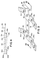
- Each corrugated ring 30,31 of the illustrated embodiment comprises alternating upper pads 30a,31a and lower pads 30b,31b connected by braces 30c,31c. Because the upper pads 30a,31a and lower pads 30b,31b alternate with one another, very little of the surface area of the porous filter 20 is actually contacted by the narrow rings 30,31. Consequently, blinding of the porous filter 20 by the spacer 22 is minimized. In addition, this arrangement of pads 30a,31a,30b,31b and braces 30c,31c provides numerous openings. Consequently, the rings 30,31 present little resistance to flow. The fluid freely flows amongst and through the rings 30,31, again, without any dead spots or stagnant areas, minimizing the residence time of the fluid between the filter elements 12.
- the outer surfaces of the upper pads 30a,31a define an upper surface 30d,31d for each ring 30,31 which contacts the upper filter element 12, while the outer surfaces of the lower pads 30b,31b define a lower surface 30e,31e for each ring 30,31 which contacts the lower filter element 12. Because the filter elements 12 in the illustrated embodiment are generally flat, the upper surfaces 30d,31d as well as the lower surfaces 30e,31e of the rings, 30,31 are generally coplanar. For more irregularly shaped filter elements, the upper surfaces, as well as the lower surfaces, of the inner and outer rings may be curved or may lie in different planes.
- the rings 30,31 are rigidly connected to one another by struts 32 which extend between the rings 30,31, as shown in Figure 3.
- the struts may be configured in a variety of ways, they are preferably arranged to provide ample open space between the rings.
- the upper 30d,31d and lower 30e,31e surfaces of the adjacent rings 30,31 define an envelope and the struts 32 preferably extend radially between the rings 30,31 spaced from the outer boundaries of the envelope, as shown in Figure 4. Consequently, when the spacer 22 is sandwiched between adjacent filter elements 12, there are openings between the struts 32 and the upper and lower filter elements 12. These openings further minimize any blinding of the porous filter 20 as well as the resistance to fluid flow and the residence time of the fluid between the filter elements 12.
- the positioning arrangement 24 of the spacer 22 serves to maintain the corrugated body 23 in position between adjacent filter elements 12 and it may be variously configured.
- the positioning arrangement may be arranged to face the outer periphery of one or both of the adjacent filter elements so that the outer periphery of each filter element serves as a stop.
- the portion of the positioning arrangement which faces the filter elements may be spaced from the outer periphery of the filter element, allowing some lateral motion of the corrugated body 23 between the filter elements 12.
- the positioning arrangement 24 engages the outer periphery of the filter element, preventing any lateral motion of the corrugated body 23.
- a positioning arrangement which faces the outer periphery of the filter elements may be constructed in a variety of ways including, for example, as a generally annular lip which extends beyond and faces one or both of the adjacent filter elements 12.
- the positioning arrangement 24 comprises a plurality of circumferentially spaced fingers 33 which extend outwardly from the outermost ring 31 slightly beyond the filter elements 12 and face only one of the adjacent filter elements 12.
- the fingers 33 are shown as radial extensions of the struts 32, they may extend from the outer ring 31 circumferentially offset from the struts 32.
- Each of the fingers 33 includes a radial projection 34 which extends outwardly from a pad, e.g., an upper pad 31a, and an axially extending flange 35 which faces the filter element 12.
- the spacer need not be positively attached to the filter element but may be maintained in place simply by the flanges 35 and by the compressive forces between adjacent filter elements 12. This allows the spacer to be easily removed, cleaned, and reassembled in the filter assembly.
- the fingers 33 are dimensioned so all of the flanges 35 engage and fit snugly against the outer periphery of the filter element 12.
- the flanges 35 may be hooked over the outer periphery of the filter element or they may extend axially far enough that the filter element 12 is unable to move up and over any of the flanges 35.
- the spacer may be positively attached to the filter elements, for example, by welding the spacer to the outer periphery of the filter elements.
- a second positioning arrangement 24′ may comprise a plurality of circumferentially spaced fingers 33′ similar to those of the first positioning arrangement 24 shown in Figures 1-4.
- the flanges 35′ of the second positioning arrangement 24′ may be shorter than those of the first positioning arrangement 24.
- the flanges 35′ of the second positioning arrangement 24′ need only be long enough to extend into a weld 36 at the outer periphery of the filter element 12, positively attaching the spacer to the filter element.
- a third positioning arrangement 24′′ is similar to the second positioning arrangement 24′, but the fingers 33′′ do not include a flange. Instead, the radial projections 34′′ extend along the surface of the filter element 12 and into a weld 36 at the outer periphery of the filter element 12, positively attaching the spacer to the filter element.
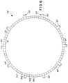
- the spacer may also be positively attached to the filter element by a fourth positioning arrangement 24′′′ which includes one or more spring clips 40, as further shown in Figure 5.
- the fourth positioning arrangement 24′′′ includes a plurality of circumferentially spaced fingers 33′′′, some including a radial projection 34′′′ and a spring clip 40 at the end of the radial projection 34′′′. Any number of fingers may include spring clips, but a preferred embodiment has only three spring clips 40 spaced about 120° apart.
- the spring clip 40 may be unitarily formed with the radial projection. However, in the preferred embodiment, the spring clip 40 is a separate component and has an elongated tang 41 which is fixed to the end of the radial projection 34′′′, e.g., by a weld.
- the spring clip 40 further has a clip portion 42 which is arranged to face and clip onto the outer periphery of a filter element. All of the clip portions 42 may extend axially in the same direction allowing the spacer to be clipped to a single filter element 12. Alternatively, some of the clip portions 42 may extend axially in opposite directions, allowing the spacer to be clipped to both adjacent filter elements 12.
- Positively attaching the spacer to a filter element 12 by a spring clip 40 has several advantages.
- the spring clips 40 ensure that the spacers are maintained in position as the fluid flows through the filter assembly. Yet, the spring clips 40 are easily detached from the filter elements, greatly facilitating disassembly, cleaning, and reassembly.
- the spacer may be formed from any material which has sufficient structural integrity to support the filter elements, which is compatible with the fluid being filtered, and which can withstand the process conditions encountered.
- the spacer may be formed from a polymeric material, such as plastic, which has been injection molded.
- the spacer may be formed from a metal, such as stainless steel, which has been stamped from sheet steel and then corrugated in a die. Preferred metals include stainless steel and InconelTM, a metal alloy.
- the spacer includes a spring clip, the entire spacer or, preferably, only the spring clip may be fashioned from a spring steel.
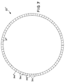
- a second spacer 22′ embodying the invention comprises only one ring 31′ but is otherwise very similar to the spacer 22 shown in Figure 2. (Corresponding components of the two embodiments are labeled with identical reference numerals.) For example, any of the positioning arrangements previously described may be included in the second spacer 22′.
- a single ring 31′ can be sufficient to support the filter element 12.
- the single ring 31′ preferably has an outer diameter less than the diameter of the filter element 12 but large enough to provide support along the outer edge of the filter element 12. Further, limiting the number of rings to one significantly reduces the impediments to fluid flow between the adjacent filter elements 12 and also minimizes blinding of the filter elements 12.
- a third spacer 22′′ embodying the present invention includes only a corrugated body 23, such as a single ring 31′′ which may be similar to the ring 31′ of the second spacer 22′.
- the third spacer 22′′ has no positioning arrangement.
- the third spacer 22′′ may be reliably maintained in position without a positioning arrangement. This further reduces the impediments to fluid flow between adjacent filter elements 12 and minimizes blinding of the filter elements 12.
- the inner diameter of the ring 31′,31′′ of each the second and third spacers 22′,22′′ may be larger than the inner diameter of a filter element 12 and no smaller than about one-third of the outer diameter of the filter element. Further, the inner diameter of each ring 31′,31′′ is preferably at least about 10% larger than the diameter of the hub 15. Therefore, the second and third spacers 22′,22′′ define openings 25′,25′′ which provide significant space between the hub 15 and the spacer 22′′. Further, the second and third spacers 22′,22′′ are free of any structure which extends into the openings 25′,25′′. Therefore, there is no impediment to fluid flow in the vicinity of the hub and fluid freely flows within the deepest recesses between the adjacent filter elements without any dead spots or stagnant areas.
Landscapes
- Chemical & Material Sciences (AREA)
- Chemical Kinetics & Catalysis (AREA)
- Filtration Of Liquid (AREA)
- Filtering Of Dispersed Particles In Gases (AREA)
- External Artificial Organs (AREA)
- Lubrication Details And Ventilation Of Internal Combustion Engines (AREA)
Description
Claims (18)
- A filter assembly comprising a spacer (22;22';22'') positioned between first and second generally disc-shaped filter elements (12) and around a hub (15), the spacer (22;22';22'') comprising a corrugated body (23) having an opening (25;25';25'') characterized in that the opening (25;25';25'') is at least 10% greater than the diameter of the hub (15) and is no smaller than about one-third of the outer diameter of the first filter element (12), the spacer (22;22';22'') being free of any structure which extends into the opening (25;25';25'').
- The filter assembly of claim 1 wherein the body (23) consists of a single ring (31'') and the body is free of any structure which extends outwardly from the ring (31'').
- The filter assembly of claim 1 wherein the body includes at least one ring (31;31';31'').
- The filter assembly of claim 1 wherein the body (23) includes a plurality of nested rings (30,31) connected to one another.
- The filter assembly of claim 4 wherein the body (23) includes no more than two rings (30,31).
- The filter assembly of claim 4 wherein the diameter of the outermost ring (31) is only slightly less than the diameter of the first filter element (12).
- The filter assembly of claim 4 wherein each of the rings (30,31) has a first surface (30a,31a) and the first surfaces (30a,31a) are coplanar.
- The filter assembly of claim 7 wherein each of the rings (30,31) has a second surface (30b,31b) opposite to the first surface (30a,31a) and the second surfaces (30b,31b) are coplanar.
- The filter assembly of claim 4 wherein the body (23) further comprises one or more struts (32) which extend between and connect the rings (30,31).
- The filter assembly according to claim 9 wherein the struts (32) extend radially between the rings (30,31).
- The filter assembly of claim 9 wherein each ring (30,31) has first and second opposing surfaces (30a,30b,31a,31b), the first and second surfaces (30a,30b,31a,31b) of adjacent rings (30,31) being axially spaced, and wherein the struts (32) extend between the adjacent rings (30,31) within the envelope (III) and are spaced from the outer boundaries of the envelope (III).
- The filter assembly of claim 1 further comprising a positioning arrangement (24;24') which extends outwardly from the body (23) to the outer periphery of at least one of the filter elements (12).
- The filter assembly of claim 12 wherein the positioning arrangement includes a plurality of fingers (24,24',24'').
- The filter assembly of claim 13 wherein at least one finger (24;24') includes a projection (34) extending radially outwardly from the outermost ring (31) and a flange (35) extending axially from the projection (34).
- The filter assembly of claim 14 wherein the flange (35) is arranged to face the outer periphery of said one filter element (12).
- The filter assembly of claim 14 wherein at least one finger (34'') includes a spring clip (40).
- The filter assembly of claim 13 wherein each finger consists of a radial projection (34'').
- A filter assembly according to any one of claims 1 to 17 and further comprising a housing (11) having an inlet (13) and an outlet (14); at least the first and second, generally disc-shaped, filter elements (12) being stacked inside the housing (11), each filter element (12) having an exterior which communicates with the inlet (13) and the stack of filter elements (12) having a central channel (17) which commuicates with the outlet (14).
Applications Claiming Priority (2)
| Application Number | Priority Date | Filing Date | Title |
|---|---|---|---|
| US07/759,914 US5271838A (en) | 1991-09-13 | 1991-09-13 | Filter assembly with filter elements separated by spacers |
| US759914 | 1991-09-13 |
Publications (3)
| Publication Number | Publication Date |
|---|---|
| EP0532237A2 EP0532237A2 (en) | 1993-03-17 |
| EP0532237A3 EP0532237A3 (en) | 1993-05-26 |
| EP0532237B1 true EP0532237B1 (en) | 1998-01-14 |
Family
ID=25057444
Family Applications (1)
| Application Number | Title | Priority Date | Filing Date |
|---|---|---|---|
| EP92308033A Expired - Lifetime EP0532237B1 (en) | 1991-09-13 | 1992-09-04 | Filter assembly with filter elements separated by spacers |
Country Status (6)
| Country | Link |
|---|---|
| US (1) | US5271838A (en) |
| EP (1) | EP0532237B1 (en) |
| JP (1) | JP2735439B2 (en) |
| KR (1) | KR0142860B1 (en) |
| CA (1) | CA2077861A1 (en) |
| DE (1) | DE69224022T2 (en) |
Families Citing this family (20)
| Publication number | Priority date | Publication date | Assignee | Title |
|---|---|---|---|---|
| US5384044A (en) * | 1993-09-07 | 1995-01-24 | Techniweave, Inc. | Fluid separation devices and methods of making same |
| US5453117A (en) * | 1994-03-22 | 1995-09-26 | Luwa Ag | Fluid filter and method of separating entrained particulate matter from a moving fluid stream |
| US5520807A (en) * | 1994-05-11 | 1996-05-28 | Uop | Stacked fluid-separation membrane disk module assemblies |
| US5536405A (en) * | 1994-05-11 | 1996-07-16 | Uop | Stacked membrane disk assemblies for fluid separations |
| US5707517A (en) * | 1995-11-27 | 1998-01-13 | Membrex, Inc. | Immersible rotary disc filtration device |
| DE19618090A1 (en) * | 1996-05-06 | 1997-11-13 | Hoechst Diafoil Gmbh | Filter device for evenly filtering plastic melts |
| US5993674A (en) * | 1998-02-24 | 1999-11-30 | Membrex, Inc. | Rotary disc filtration device with means to reduce axial forces |
| CO4950571A1 (en) * | 1998-06-10 | 2000-09-01 | Cutore Gaetano | RING SEALING ELEMENT FOR FILTRATION CARTRIDGES, FILTRATION CARTRIDGE THAT INCLUDES SUCH FILTRATION ELEMENT AND UNIT THAT INCLUDES SUCH CARTRIDGE |
| US6099608A (en) * | 1998-07-30 | 2000-08-08 | 3M Innovative Properties Company | Rotating filtration cartridge and blower for HVAC applications |
| US6712966B1 (en) | 1999-02-04 | 2004-03-30 | Cuno Incorporated | Graded particle-size retention filter medium for cell-type filter unit |
| US6939466B2 (en) * | 1998-08-17 | 2005-09-06 | Cuno Incorporated | Graded particle-size retention filter medium for fluid filtration unit with improved edge seal |
| NZ332958A (en) * | 1998-11-23 | 2001-06-29 | Gould Gt Systems Nz Ltd | Filter apparatus including a housing, disc filters and conduit from filters to output |
| US20070017879A1 (en) * | 1998-12-03 | 2007-01-25 | Stephen Proulx | Filtration cartridge and process for filtering a slurry |
| DE19857751A1 (en) * | 1998-12-15 | 2000-06-29 | Schenk Filterbau Gmbh | Module filter with at least one inlet for unfiltrate and one outlet for the filtrate and with at least one filter module |
| US20040118766A1 (en) * | 2000-02-03 | 2004-06-24 | Pulek John L. | Graded particle-size retention filter medium for cell-type filter unit |
| DE60003202T2 (en) * | 1999-09-17 | 2004-05-06 | Mykrolis Corp., Bedford | METHOD AND FILTER FOR FILTERING A SLUDGE |
| US6962480B2 (en) * | 2003-11-12 | 2005-11-08 | Honeywell International, Inc. | Thermally stabilized turbine scroll retention ring for uniform loading application |
| JP5176856B2 (en) * | 2008-10-10 | 2013-04-03 | 東レ株式会社 | Filter spacers, filter assemblies and films |
| WO2017112806A1 (en) * | 2015-12-22 | 2017-06-29 | Clarification Technology, Inc. | Multilayer filtration device |
| US12220657B2 (en) * | 2021-04-30 | 2025-02-11 | Pall Corporation | Filter disk segments |
Citations (1)
| Publication number | Priority date | Publication date | Assignee | Title |
|---|---|---|---|---|
| EP0284404A2 (en) * | 1987-03-27 | 1988-09-28 | Pall Corporation | Filter disc |
Family Cites Families (21)
| Publication number | Priority date | Publication date | Assignee | Title |
|---|---|---|---|---|
| BE433113A (en) * | ||||
| US837845A (en) * | 1903-03-06 | 1906-12-04 | Karl Kiefer | Filtering element. |
| US1146499A (en) * | 1914-12-12 | 1915-07-13 | Francis Jaszkowiak | Well-filter. |
| US1927228A (en) * | 1930-06-28 | 1933-09-19 | Charles A Compton | Filter |
| US2444147A (en) * | 1945-03-15 | 1948-06-29 | Air Maze Corp | Liquid filter element |
| US2630228A (en) * | 1948-10-23 | 1953-03-03 | Air Valve Inc | Fuel filter |
| US2750047A (en) * | 1949-11-02 | 1956-06-12 | United Aircraft Corp | Filter |
| GB697526A (en) * | 1951-01-29 | 1953-09-23 | Ricardo & Co Engineers | Improvements in or relating to liquid storage and carburetting apparatus |
| US2654440A (en) * | 1951-10-18 | 1953-10-06 | Fram Corp | Filter element formed of paper impregnated with thermoplastic resin |
| US2798718A (en) * | 1951-10-26 | 1957-07-09 | William E Gross | Canister spring |
| FR1090663A (en) * | 1953-10-02 | 1955-04-01 | Device to prevent deformation of filter media discs in stacked filter blocks or cartridges | |
| US3083834A (en) * | 1959-09-01 | 1963-04-02 | Pall Corp | Filter unit |
| US3294241A (en) * | 1963-12-11 | 1966-12-27 | American Mach & Foundry | Easily assembled filter assembly |
| US3398834A (en) * | 1966-10-10 | 1968-08-27 | Aerojet General Co | Reverse osmosis water purification apparatus and cell therefor |
| US3537592A (en) * | 1968-07-29 | 1970-11-03 | Ogden Filter Co Inc | Cartridge of spaced wall filter elements and spacers |
| US4704207A (en) * | 1985-12-02 | 1987-11-03 | Cuno Incorporated | Filter cartridge including external cell separators |
| JPH0671535B2 (en) * | 1986-04-01 | 1994-09-14 | 株式会社キッツ | Flat thin film laminated filter |
| DE3728825A1 (en) * | 1986-08-28 | 1988-03-03 | Fuji Photo Film Co Ltd | FILTER CARTRIDGE |
| DE3635728A1 (en) * | 1986-10-21 | 1988-04-28 | Bosch Gmbh Robert | LIQUID FILTER, ESPECIALLY FOR FUELS |
| US4902420A (en) * | 1987-03-27 | 1990-02-20 | Pall Corporation | Segmented filter disc with slotted support and drainage plate and support spacer |
| JPH0620588Y2 (en) * | 1988-04-13 | 1994-06-01 | フィルトレーション株式会社 | Polymer distribution plate |
-
1991
- 1991-09-13 US US07/759,914 patent/US5271838A/en not_active Expired - Lifetime
-
1992
- 1992-09-04 EP EP92308033A patent/EP0532237B1/en not_active Expired - Lifetime
- 1992-09-04 DE DE69224022T patent/DE69224022T2/en not_active Expired - Fee Related
- 1992-09-09 KR KR1019920016546A patent/KR0142860B1/en not_active Expired - Fee Related
- 1992-09-09 CA CA002077861A patent/CA2077861A1/en not_active Abandoned
- 1992-09-14 JP JP4245021A patent/JP2735439B2/en not_active Expired - Fee Related
Patent Citations (1)
| Publication number | Priority date | Publication date | Assignee | Title |
|---|---|---|---|---|
| EP0284404A2 (en) * | 1987-03-27 | 1988-09-28 | Pall Corporation | Filter disc |
Also Published As
| Publication number | Publication date |
|---|---|
| EP0532237A2 (en) | 1993-03-17 |
| KR0142860B1 (en) | 1998-07-15 |
| EP0532237A3 (en) | 1993-05-26 |
| CA2077861A1 (en) | 1993-03-14 |
| US5271838A (en) | 1993-12-21 |
| DE69224022T2 (en) | 1998-07-02 |
| DE69224022D1 (en) | 1998-02-19 |
| JP2735439B2 (en) | 1998-04-02 |
| KR930005655A (en) | 1993-04-20 |
| JPH05192518A (en) | 1993-08-03 |
Similar Documents
| Publication | Publication Date | Title |
|---|---|---|
| US5271838A (en) | Filter assembly with filter elements separated by spacers | |
| US4902420A (en) | Segmented filter disc with slotted support and drainage plate and support spacer | |
| EP0285031B1 (en) | Improved separator for cell type fiter cartridges | |
| EP0674931B1 (en) | Hub ring and supporting plate for a filter and methods for manufacturing these members | |
| US4876007A (en) | Plate-type filter cartridge with internal support | |
| EP0284404A2 (en) | Filter disc | |
| US4704207A (en) | Filter cartridge including external cell separators | |
| JPH067614A (en) | Sealed connector | |
| JP3683592B2 (en) | Filter device with filter disc | |
| US3256989A (en) | Screw neck filter cartridge | |
| US20020195388A1 (en) | Advanced leaf disc filter segment | |
| AU603734B2 (en) | Filter cartridge assembly and method of making | |
| US4328103A (en) | Structural strainer | |
| JP2004501742A (en) | Filter module | |
| EP0193653A2 (en) | Multiple-disc type filter with extensible support | |
| CA2514162C (en) | Spacer element for guiding flow media | |
| US6306300B1 (en) | Filter cartridges and filter cells | |
| CA1263320A (en) | Filter means with a segmental construction | |
| US2583963A (en) | Filter | |
| US6835309B2 (en) | Filter cartridge assembly | |
| KR100323574B1 (en) | Disc Filter Elements and Disc Filter Systems | |
| SU1242214A1 (en) | Filter element | |
| KR100311261B1 (en) | Fluid Filter Filtration Disc Filter | |
| JPH02115009A (en) | Disc filter | |
| JP3707870B2 (en) | Filter hub ring and method of manufacturing the same |
Legal Events
| Date | Code | Title | Description |
|---|---|---|---|
| PUAI | Public reference made under article 153(3) epc to a published international application that has entered the european phase |
Free format text: ORIGINAL CODE: 0009012 |
|
| AK | Designated contracting states |
Kind code of ref document: A2 Designated state(s): DE FR GB IT |
|
| PUAL | Search report despatched |
Free format text: ORIGINAL CODE: 0009013 |
|
| AK | Designated contracting states |
Kind code of ref document: A3 Designated state(s): DE FR GB IT |
|
| 17P | Request for examination filed |
Effective date: 19930903 |
|
| 17Q | First examination report despatched |
Effective date: 19940722 |
|
| GRAG | Despatch of communication of intention to grant |
Free format text: ORIGINAL CODE: EPIDOS AGRA |
|
| GRAH | Despatch of communication of intention to grant a patent |
Free format text: ORIGINAL CODE: EPIDOS IGRA |
|
| GRAH | Despatch of communication of intention to grant a patent |
Free format text: ORIGINAL CODE: EPIDOS IGRA |
|
| GRAA | (expected) grant |
Free format text: ORIGINAL CODE: 0009210 |
|
| AK | Designated contracting states |
Kind code of ref document: B1 Designated state(s): DE FR GB IT |
|
| REF | Corresponds to: |
Ref document number: 69224022 Country of ref document: DE Date of ref document: 19980219 |
|
| ITF | It: translation for a ep patent filed | ||
| ET | Fr: translation filed | ||
| PGFP | Annual fee paid to national office [announced via postgrant information from national office to epo] |
Ref country code: GB Payment date: 19980828 Year of fee payment: 7 |
|
| PGFP | Annual fee paid to national office [announced via postgrant information from national office to epo] |
Ref country code: FR Payment date: 19980909 Year of fee payment: 7 |
|
| PGFP | Annual fee paid to national office [announced via postgrant information from national office to epo] |
Ref country code: DE Payment date: 19980914 Year of fee payment: 7 |
|
| PLBE | No opposition filed within time limit |
Free format text: ORIGINAL CODE: 0009261 |
|
| STAA | Information on the status of an ep patent application or granted ep patent |
Free format text: STATUS: NO OPPOSITION FILED WITHIN TIME LIMIT |
|
| 26N | No opposition filed | ||
| PG25 | Lapsed in a contracting state [announced via postgrant information from national office to epo] |
Ref country code: GB Free format text: LAPSE BECAUSE OF NON-PAYMENT OF DUE FEES Effective date: 19990904 |
|
| GBPC | Gb: european patent ceased through non-payment of renewal fee |
Effective date: 19990904 |
|
| PG25 | Lapsed in a contracting state [announced via postgrant information from national office to epo] |
Ref country code: FR Free format text: LAPSE BECAUSE OF NON-PAYMENT OF DUE FEES Effective date: 20000531 |
|
| PG25 | Lapsed in a contracting state [announced via postgrant information from national office to epo] |
Ref country code: DE Free format text: LAPSE BECAUSE OF NON-PAYMENT OF DUE FEES Effective date: 20000701 |
|
| REG | Reference to a national code |
Ref country code: FR Ref legal event code: ST |
|
| PG25 | Lapsed in a contracting state [announced via postgrant information from national office to epo] |
Ref country code: IT Free format text: LAPSE BECAUSE OF NON-PAYMENT OF DUE FEES;WARNING: LAPSES OF ITALIAN PATENTS WITH EFFECTIVE DATE BEFORE 2007 MAY HAVE OCCURRED AT ANY TIME BEFORE 2007. THE CORRECT EFFECTIVE DATE MAY BE DIFFERENT FROM THE ONE RECORDED. Effective date: 20050904 |