EP0193653A2 - Multiple-disc type filter with extensible support - Google Patents
Multiple-disc type filter with extensible support Download PDFInfo
- Publication number
- EP0193653A2 EP0193653A2 EP85116362A EP85116362A EP0193653A2 EP 0193653 A2 EP0193653 A2 EP 0193653A2 EP 85116362 A EP85116362 A EP 85116362A EP 85116362 A EP85116362 A EP 85116362A EP 0193653 A2 EP0193653 A2 EP 0193653A2
- Authority
- EP
- European Patent Office
- Prior art keywords
- filter
- multiplicity
- stack
- end elements
- engagement
- Prior art date
- Legal status (The legal status is an assumption and is not a legal conclusion. Google has not performed a legal analysis and makes no representation as to the accuracy of the status listed.)
- Withdrawn
Links
- 238000001914 filtration Methods 0.000 claims description 29
- 239000012530 fluid Substances 0.000 claims description 8
- 230000000712 assembly Effects 0.000 description 13
- 238000000429 assembly Methods 0.000 description 13
- 125000006850 spacer group Chemical group 0.000 description 11
- 238000004140 cleaning Methods 0.000 description 5
- 239000002245 particle Substances 0.000 description 5
- 238000011144 upstream manufacturing Methods 0.000 description 4
- 239000007788 liquid Substances 0.000 description 3
- 230000000717 retained effect Effects 0.000 description 2
- XLYOFNOQVPJJNP-UHFFFAOYSA-N water Substances O XLYOFNOQVPJJNP-UHFFFAOYSA-N 0.000 description 2
- 230000006835 compression Effects 0.000 description 1
- 238000007906 compression Methods 0.000 description 1
- 238000007689 inspection Methods 0.000 description 1
- 230000007257 malfunction Effects 0.000 description 1
- 238000000034 method Methods 0.000 description 1
- 230000004048 modification Effects 0.000 description 1
- 238000012986 modification Methods 0.000 description 1
Images

Classifications
-
- B—PERFORMING OPERATIONS; TRANSPORTING
- B01—PHYSICAL OR CHEMICAL PROCESSES OR APPARATUS IN GENERAL
- B01D—SEPARATION
- B01D29/00—Filters with filtering elements stationary during filtration, e.g. pressure or suction filters, not covered by groups B01D24/00 - B01D27/00; Filtering elements therefor
- B01D29/11—Filters with filtering elements stationary during filtration, e.g. pressure or suction filters, not covered by groups B01D24/00 - B01D27/00; Filtering elements therefor with bag, cage, hose, tube, sleeve or like filtering elements
- B01D29/13—Supported filter elements
- B01D29/15—Supported filter elements arranged for inward flow filtration
-
- B—PERFORMING OPERATIONS; TRANSPORTING
- B01—PHYSICAL OR CHEMICAL PROCESSES OR APPARATUS IN GENERAL
- B01D—SEPARATION
- B01D29/00—Filters with filtering elements stationary during filtration, e.g. pressure or suction filters, not covered by groups B01D24/00 - B01D27/00; Filtering elements therefor
- B01D29/44—Edge filtering elements, i.e. using contiguous impervious surfaces
- B01D29/46—Edge filtering elements, i.e. using contiguous impervious surfaces of flat, stacked bodies
-
- B—PERFORMING OPERATIONS; TRANSPORTING
- B01—PHYSICAL OR CHEMICAL PROCESSES OR APPARATUS IN GENERAL
- B01D—SEPARATION
- B01D29/00—Filters with filtering elements stationary during filtration, e.g. pressure or suction filters, not covered by groups B01D24/00 - B01D27/00; Filtering elements therefor
- B01D29/50—Filters with filtering elements stationary during filtration, e.g. pressure or suction filters, not covered by groups B01D24/00 - B01D27/00; Filtering elements therefor with multiple filtering elements, characterised by their mutual disposition
- B01D29/52—Filters with filtering elements stationary during filtration, e.g. pressure or suction filters, not covered by groups B01D24/00 - B01D27/00; Filtering elements therefor with multiple filtering elements, characterised by their mutual disposition in parallel connection
- B01D29/54—Filters with filtering elements stationary during filtration, e.g. pressure or suction filters, not covered by groups B01D24/00 - B01D27/00; Filtering elements therefor with multiple filtering elements, characterised by their mutual disposition in parallel connection arranged concentrically or coaxially
-
- B—PERFORMING OPERATIONS; TRANSPORTING
- B01—PHYSICAL OR CHEMICAL PROCESSES OR APPARATUS IN GENERAL
- B01D—SEPARATION
- B01D29/00—Filters with filtering elements stationary during filtration, e.g. pressure or suction filters, not covered by groups B01D24/00 - B01D27/00; Filtering elements therefor
- B01D29/62—Regenerating the filter material in the filter
- B01D29/70—Regenerating the filter material in the filter by forces created by movement of the filter element
-
- B—PERFORMING OPERATIONS; TRANSPORTING
- B01—PHYSICAL OR CHEMICAL PROCESSES OR APPARATUS IN GENERAL
- B01D—SEPARATION
- B01D2201/00—Details relating to filtering apparatus
- B01D2201/04—Supports for the filtering elements
- B01D2201/0415—Details of supporting structures
Definitions
- the present invention relates to filters and particularly to multiple-disc type filters useful in filtering particles from water and in many other applications.
- Multiple-disc type filters generally include a housing in which the filter body within the housing is in the form of a stack of like, centrally-apertured, filter discs of substantially uniform thickness along their widths and having grooved side faces defining filtering channels between the adjacent discs in the stack.
- the outer race of the stack of filter discs constitutes the upstream side of the filter, in which case the fluid being filtered passes from the outer face to the inner face of the stack.
- the inner face of the stack constitutes the upstream side of the filter, in which case the fluid being filtered passes from the inner to the outer face through the filter stack.
- the multiple-disc filter has a larger capacity for removing and retaining dirt particles, since these may be retained also between the side faces of the discs, in addition to being retained on the upstream surface as in the cylindrical-screen type filter.
- Another advantage in the multiple-disc filter is that it is not as easily ruptured as the screen type and therefore there is less danger that because of a malfunction, unfiltered water may pass through and clog sprinklers or other devices downstream of the filter.
- the latter advantage is particularly important in self-cleaning filters wherein the upstream face of the filter is cleaned by a cleaning nozzle which, in the case of a screen-type filter, may rupture the screen by particles becoming wedged between the cleaning nozzle and the filter screen.
- the stack of discs in the multiple-disc type filter has hitherto been supported internally by a cylinder pierced with holes so as to allow the fluid being filtered to flow therethrough. Since the stack is held in position by fastening members at each end, as for example by annular screws which move about threaded extensions of the cylinder at each end thereof, the removal of discs for inspection or replacement can be a laborious process. The necessity for the threaded extensions adds to the size and cost of the equipment and is not practical for non-in line systems.
- the present invention relates to a novel form of support for the stack of discs in a multiple-disc type filter which overcomes the disadvantages of the cylindrical kind of support.
- a multiple-disc type filter comprising a stack of filter disks disposed in a housing, an extensible support for the stack of filter disks, the extensible support including first and second end elements and a multiplicity of rod members joining at least one of the first and second end elements in sliding relationship, and stop apparatus for limiting the extension of the support.
- the multiplicity of rod members are arranged for fixed engagement with the first end element and for slidable supporting engagement with the second end element.
- the rod members are arranged for slidable supporting engagment with both the first and second end elements.
- the second end element defines a plurality of slidable mounting channels for accomodating the rod members, a plate portion defining a central fluid flow aperture and a stop engagement portion.
- the first end element is constructed to be identical to the second end element.
- a spacer support which fixedly joins the multiplicity of rod members intermediate the first and second end elements.
- the stop apparatus comprises an elongated rod extending axially through the stack and having transverse extensions adjacent at least one end thereof for engaging the stop engagemeiit portions of the second end element for preventing disengagement of the second end element from the rods.
- the outer extent of the spacer support corresponds to the inner radius of the stack of filter disks.
- the outer extent of the spacer support corresponds to the outer radius of the stack of filter disks.
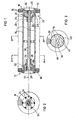
- the filtration unit comprises first and second end assemblies 10 and 12, which are typically identical, a plurality of support rods 14, which are slidably mounted in a generally cylindrical pattern on the first and second end assemblies and a stack of filter discs 16 which are supported between end assemblies 10 and 12 on support rods 14.
- the first and second end assemblies 10 and 12 each typically comprise a generally planar end portion 18 having a central aperture 20.
- a plurality of ribs 22 extend from planar end portion 18.
- Each rib includes a first axial portion 24 which defines a rod support, and an inwardly directed portion 26.
- the inwardly directed portions 26 of the individual ribs 22 terminate at a cylindrical collar 28.
- a central rod or shaft 30 extends axially along the entire length of the filter disc stack and through respective collars 28 on the first and second end assemblies. Stopper sleeves 32 are formed adjacent the ends of the central rod or shaft 30 at both ends thereof, outwardly of respective collars 28 to restrict the amount that the first and second end assemblies 10 and 12 may be axially separated along the longitudinal axis 34 of the filtration unit.
- a spacer 36 is fixedly mounted onto central shaft 30 and to rods 14 approximately halfway between first and second end assemblies ID and 12. Spacer 36 provides structural stability to the support structure for the stack of filter discs. Spacer 36 is constructed to have an inner collar member 38 and an outer ring 40 which defines slots for seating of rods 14. The inner collar member 38 and outer ring 40 are joined by a plurality of spokes 42.
- both of the end assemblies are axially slidable with respect to the spacer rods 14 to permit spreading apart of the individual filter discs from discs adjacent thereto for the purpose of cleaning particles therefrom.
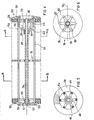
- the filtration unit comprises first and second end assemblies 50 and 52, which are normally not identical, a plurality of support rods 54, which are arranged in a generally cylindrical pattern and fixedly mounted onto the first end assembly 50 and slidably mounted onto the second end assembly 52.
- a stack of filter discs 56 is supported between end assemblies 50 and 52 on support rods 54.
- First end assembly 50 comprises a planar end portion 51 in which are formed a plurality of bores 53 for end seating of rods 54 and a seating collar 55 which may communicate with an aperture 57 formed in end portion 51.
- the second end assembly 52 typically comprises a generally planar end portion 58 having a central aperture 60.
- a plurality of ribs 62 extend from planar end portion 58.
- Each rib includes a first axial portion 64 which defines a rod support, and an inwardly directed portion bb.
- the inwardly directed portions b6 of the individual ribs 62 terminate at a cylindrical collar 68.
- a central rod or shaft 70 extends axially along the entire length of the filter disc stack.
- Shaft 70 is fixedly seated in collar 55 on end assembly 50 and extends slidably through collar 68 on the second end assembly.
- a stopper sleeve 72 is formed adjacent the end of the central rod or shaft 70 at the end thereof which lies outwardly of collar 58 to restrict the amount that the first and second end assemblies 50 and 52 may be axially separated along the longitudinal axis 74 of the filtration unit.
- a spacer 76 is fixedly mounted onto central shaft 70 and slidably mounted onto rods 54 approximately halfway between first and second end assemblies 50 and 52.
- Spacer 76 provides structural stability to the support structure for the stack of filter discs.
- Spacer 76 is constructed to have an inner collar member 78 and an outer ring 80 which defines holes 82 for slidable engagement with rods 54.
- Ring 80 extends to an outer radius which corresponds to the outer dimensions of filter discs 56.
- the inner collar member 78 and outer ring 80 are joined by a plurality of spokes 82.
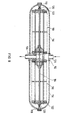
- Fig 7 illustrates a filter employing a filtration unit of the type described in connection with Figs. 4 - 6. It is appreciated that alternatively, the filtration unit may be of the type illustrated in Figs. 1 - 3 or have a combination of the features of the two:.. embodiments.
- the filter includes a generally bell-shaped housing 90, which is mounted on a mounting base 92.
- a filtration unit of the type described hereinabove is disposed within housing 90.
- a central securing rod 94 having first and second threaded ends 95 and 97, is secured to base 92 at threaded end 95 by means of internally threaded nuts 96 and 98.
- a nut 100 threaded at end 97, secures the filtration unit onto base 92 and maintains the nut in its non-extended orientation for filtering operation and an additional nut 102 secures housing 90 onto base 92.
- base 92 defines a liquid inlet 104 which communicates with the outer cylindrical surface of the filtration unit and a liquid outlet 106 which communicates with the inner cylindrical surface of the filtration unit.
- the arrows appearing in Fig. 7 indicate the flow of liquid through the unit. It is appreciated that base 92 may readily be modified to provide an oppositely directed flow or may be formed with a movable baffle or baffles to permit selection of the direction of flow.
- Fig. 8 illustrates a double capacity filter employing the filtration units of the type described hereinabove in connection with Figs. 4 - 6.
- two units 110 each generally of the type illustrated in Figs. 4 - 6 are placed end to end in communication with a common base 112.
- a single rod 114 threaded at both ends,. traverses the entire unit and is operative in cooperation with a pair of threaded screws 118 tq secure. the individual housing elements 116 to base 112.
- the filtration units are mounted onto base 112 by means of a pair of compression springs 120 which are seated on the axial inner facing surfaces of screws 118 and on the axially outer facing surfaces of respective end members 122 of the filtration units.
- Fluid to be filtered enters the apparatus at a port 124 and passes through the stack of filter discs from the outer cylindrical surface inwardly to the central cavity defined by the discs and out through an outlet port 126, in directions indicated by the arrows appearing in Fig. 8.
Landscapes
- Chemical & Material Sciences (AREA)
- Chemical Kinetics & Catalysis (AREA)
- Filtration Of Liquid (AREA)
Abstract
Description
- The present invention relates to filters and particularly to multiple-disc type filters useful in filtering particles from water and in many other applications.
- Multiple-disc type filters generally include a housing in which the filter body within the housing is in the form of a stack of like, centrally-apertured, filter discs of substantially uniform thickness along their widths and having grooved side faces defining filtering channels between the adjacent discs in the stack. In some applications of such filters, the outer race of the stack of filter discs constitutes the upstream side of the filter, in which case the fluid being filtered passes from the outer face to the inner face of the stack. In other applications of such filters, the inner face of the stack constitutes the upstream side of the filter, in which case the fluid being filtered passes from the inner to the outer face through the filter stack.
- Multiple-disc type filters have a number of advantages over other known types of filters, for example, the cylindrical-screen type filter. Thus, the multiple-disc filter has a larger capacity for removing and retaining dirt particles, since these may be retained also between the side faces of the discs, in addition to being retained on the upstream surface as in the cylindrical-screen type filter. Another advantage in the multiple-disc filter is that it is not as easily ruptured as the screen type and therefore there is less danger that because of a malfunction, unfiltered water may pass through and clog sprinklers or other devices downstream of the filter. The latter advantage is particularly important in self-cleaning filters wherein the upstream face of the filter is cleaned by a cleaning nozzle which, in the case of a screen-type filter, may rupture the screen by particles becoming wedged between the cleaning nozzle and the filter screen.
- The stack of discs in the multiple-disc type filter has hitherto been supported internally by a cylinder pierced with holes so as to allow the fluid being filtered to flow therethrough. Since the stack is held in position by fastening members at each end, as for example by annular screws which move about threaded extensions of the cylinder at each end thereof, the removal of discs for inspection or replacement can be a laborious process. The necessity for the threaded extensions adds to the size and cost of the equipment and is not practical for non-in line systems.
- The present invention relates to a novel form of support for the stack of discs in a multiple-disc type filter which overcomes the disadvantages of the cylindrical kind of support.
- There is thus provided in accordance with an embodiment of the present invention, a multiple-disc type filter comprising a stack of filter disks disposed in a housing, an extensible support for the stack of filter disks, the extensible support including first and second end elements and a multiplicity of rod members joining at least one of the first and second end elements in sliding relationship, and stop apparatus for limiting the extension of the support.
- According to one embodiment of the invention, the multiplicity of rod members are arranged for fixed engagement with the first end element and for slidable supporting engagement with the second end element. According to another embodiment of the invention the rod members are arranged for slidable supporting engagment with both the first and second end elements.
- According to a preferred embodiment of the invention, the second end element defines a plurality of slidable mounting channels for accomodating the rod members, a plate portion defining a central fluid flow aperture and a stop engagement portion.
- According to one embodiment of the invention, the first end element is constructed to be identical to the second end element.
- Additionally in accordance with an embodiment of the present invention there is provided a spacer support which fixedly joins the multiplicity of rod members intermediate the first and second end elements.
- Further in accordance with an embodiment of the present invention, the stop apparatus comprises an elongated rod extending axially through the stack and having transverse extensions adjacent at least one end thereof for engaging the stop engagemeiit portions of the second end element for preventing disengagement of the second end element from the rods.
- Further in accordance with an embodiment of the invention, the outer extent of the spacer support corresponds to the inner radius of the stack of filter disks.
- According to an alternative embodiment of the present invention, the outer extent of the spacer support corresponds to the outer radius of the stack of filter disks.
- The present invention will be understood and appreciated more fully from the following detailed description taken in conjunction with the drawings in which:
- Fig. 1 is a sectional illustration of a filtration unit constructed and operative in accordance with a preferred embodiment of the present invention;
- Fig. 2 is a sectional illustration of the filtration apparatus of Fig. 1 taken along the lines A - A in Fig. 1;
- Fig. 3 is a sectional illustration of the filtration apparatus of Fig. 1 taken along the lines B - B in Fig. 1;
- Fig. 4 is a sectional illustration of a filtration unit constructed and operative in accordance with an alternative embodiment of the present invention;
- Fig. 5 is a sectional illustration of the filtration apparatus of Fig. 4 taken along the lines A - A in Fig. 4;
- Fig. 6 is a sectional illustration of the filtration apparatus of Fig. 4 taken along the lines B - B in Fig. 4;
- Fig. 7 is a sectional illustration of a filter employing the filtration apparatus of Figs. 4 - 6; and
- Fig. 8 is a sectional illustrtaion of a double filter employing the filtration apparatus of Figs. 4 - 6.
- Referring now to Figs. 1 - 3, there is seen a filtration unit constructed and operative in accordance with a preferred embodiment of the present invention. The filtration unit comprises first and
second end assemblies support rods 14, which are slidably mounted in a generally cylindrical pattern on the first and second end assemblies and a stack offilter discs 16 which are supported betweenend assemblies support rods 14. - The first and
second end assemblies planar end portion 18 having acentral aperture 20. A plurality ofribs 22 extend fromplanar end portion 18. Each rib includes a firstaxial portion 24 which defines a rod support, and an inwardly directedportion 26. The inwardly directedportions 26 of theindividual ribs 22 terminate at acylindrical collar 28. - A central rod or
shaft 30 extends axially along the entire length of the filter disc stack and throughrespective collars 28 on the first and second end assemblies.Stopper sleeves 32 are formed adjacent the ends of the central rod orshaft 30 at both ends thereof, outwardly ofrespective collars 28 to restrict the amount that the first and second end assemblies 10 and 12 may be axially separated along thelongitudinal axis 34 of the filtration unit. - A
spacer 36 is fixedly mounted ontocentral shaft 30 and to rods 14 approximately halfway between first and second end assemblies ID and 12.Spacer 36 provides structural stability to the support structure for the stack of filter discs.Spacer 36 is constructed to have aninner collar member 38 and anouter ring 40 which defines slots for seating ofrods 14. Theinner collar member 38 andouter ring 40 are joined by a plurality ofspokes 42. - It is appreciated that in the embodiment of Figs. 1 - 3, both of the end assemblies are axially slidable with respect to the
spacer rods 14 to permit spreading apart of the individual filter discs from discs adjacent thereto for the purpose of cleaning particles therefrom. - Reference is now made to figs. 4 - 6 which illustrate another preferred embodiment of the invention. Here the filtration unit comprises first and
second end assemblies support rods 54, which are arranged in a generally cylindrical pattern and fixedly mounted onto thefirst end assembly 50 and slidably mounted onto thesecond end assembly 52. A stack offilter discs 56 is supported betweenend assemblies support rods 54. -
First end assembly 50 comprises aplanar end portion 51 in which are formed a plurality ofbores 53 for end seating ofrods 54 and aseating collar 55 which may communicate with anaperture 57 formed inend portion 51. - The
second end assembly 52 typically comprises a generallyplanar end portion 58 having acentral aperture 60. A plurality ofribs 62 extend fromplanar end portion 58. Each rib includes a firstaxial portion 64 which defines a rod support, and an inwardly directed portion bb. The inwardly directed portions b6 of theindividual ribs 62 terminate at acylindrical collar 68. - A central rod or
shaft 70 extends axially along the entire length of the filter disc stack.Shaft 70 is fixedly seated incollar 55 onend assembly 50 and extends slidably throughcollar 68 on the second end assembly. Astopper sleeve 72 is formed adjacent the end of the central rod orshaft 70 at the end thereof which lies outwardly ofcollar 58 to restrict the amount that the first and second end assemblies 50 and 52 may be axially separated along thelongitudinal axis 74 of the filtration unit. - A
spacer 76 is fixedly mounted ontocentral shaft 70 and slidably mounted ontorods 54 approximately halfway between first and second end assemblies 50 and 52.Spacer 76 provides structural stability to the support structure for the stack of filter discs.Spacer 76 is constructed to have aninner collar member 78 and anouter ring 80 which definesholes 82 for slidable engagement withrods 54.Ring 80 extends to an outer radius which corresponds to the outer dimensions offilter discs 56. Theinner collar member 78 andouter ring 80 are joined by a plurality ofspokes 82. - It is appreciated that in the embodiment of Figs. 4 - 6, only one of the end assemblies is axially slidable with respect to the
spacer rods 14 to permit spreading apart of the individual filter discs from discs adjacent thereto for the purpose of cleaning particles therefrom. It is further appreciated that anv of the features of the embodiment of Figs. 1 - 3 may be combined with any of the features of the embodiment of Figs. 4 - 6 to produce a suitable filtration unit, which is also within the scope of the present invention. - Reference is now made to Fig 7 which illustrates a filter employing a filtration unit of the type described in connection with Figs. 4 - 6. It is appreciated that alternatively, the filtration unit may be of the type illustrated in Figs. 1 - 3 or have a combination of the features of the two:.. embodiments. The filter includes a generally bell-shaped
housing 90, which is mounted on a mountingbase 92. A filtration unit of the type described hereinabove is disposed withinhousing 90. - A
central securing rod 94, having first and second threaded ends 95 and 97, is secured to base 92 at threadedend 95 by means of internally threadednuts nut 100, threaded atend 97, secures the filtration unit ontobase 92 and maintains the nut in its non-extended orientation for filtering operation and anadditional nut 102 secureshousing 90 ontobase 92. - In the illustrated embodiment,
base 92 defines aliquid inlet 104 which communicates with the outer cylindrical surface of the filtration unit and aliquid outlet 106 which communicates with the inner cylindrical surface of the filtration unit. The arrows appearing in Fig. 7 indicate the flow of liquid through the unit. It is appreciated thatbase 92 may readily be modified to provide an oppositely directed flow or may be formed with a movable baffle or baffles to permit selection of the direction of flow. - Reference is now made to Fig. 8 which illustrates a double capacity filter employing the filtration units of the type described hereinabove in connection with Figs. 4 - 6. In principle, two
units 110, each generally of the type illustrated in Figs. 4 - 6 are placed end to end in communication with acommon base 112. Asingle rod 114 threaded at both ends,. traverses the entire unit and is operative in cooperation with a pair of threadedscrews 118 tq secure. theindividual housing elements 116 tobase 112. The filtration units are mounted ontobase 112 by means of a pair of compression springs 120 which are seated on the axial inner facing surfaces ofscrews 118 and on the axially outer facing surfaces ofrespective end members 122 of the filtration units. Fluid to be filtered enters the apparatus at aport 124 and passes through the stack of filter discs from the outer cylindrical surface inwardly to the central cavity defined by the discs and out through anoutlet port 126, in directions indicated by the arrows appearing in Fig. 8. - It is appreciated that in this and all other embodiment of the present invention illustrated herein, the indicated direction of flow of fluid therethrough may be changed by suitable modification of the flow paths.
- It will be appreciated by persons skilled in the art that the present invention is not limited to what has been shown and described with particularity hereinabove. Rather the scope of the present invention is defined only by the claims which follow:
Claims (13)
Applications Claiming Priority (2)
| Application Number | Priority Date | Filing Date | Title |
|---|---|---|---|
| US06/709,373 US4654143A (en) | 1985-03-07 | 1985-03-07 | Multiple-disc type filter with extensible support |
| US709373 | 1985-03-07 |
Publications (2)
| Publication Number | Publication Date |
|---|---|
| EP0193653A2 true EP0193653A2 (en) | 1986-09-10 |
| EP0193653A3 EP0193653A3 (en) | 1987-01-21 |
Family
ID=24849598
Family Applications (1)
| Application Number | Title | Priority Date | Filing Date |
|---|---|---|---|
| EP85116362A Withdrawn EP0193653A3 (en) | 1985-03-07 | 1985-12-20 | Multiple-disc type filter with extensible support |
Country Status (6)
| Country | Link |
|---|---|
| US (1) | US4654143A (en) |
| EP (1) | EP0193653A3 (en) |
| ES (1) | ES296445Y (en) |
| GR (1) | GR860559B (en) |
| IL (1) | IL77257A (en) |
| PT (1) | PT82130B (en) |
Families Citing this family (14)
| Publication number | Priority date | Publication date | Assignee | Title |
|---|---|---|---|---|
| USRE34218E (en) | 1983-09-02 | 1993-04-13 | Easily-cleanable filters | |
| IL74873A (en) * | 1985-04-10 | 1990-07-12 | Drori Mordeki | Multiple disc type filter and disc construction useful therein |
| IL75473A0 (en) * | 1985-06-10 | 1985-10-31 | Drori Mordeki | Improved disc filter |
| US4935126A (en) | 1986-02-11 | 1990-06-19 | Mordeki Drori | Filtering apparatus |
| US4978450A (en) | 1986-02-11 | 1990-12-18 | Mordeki Drori | Filtering element |
| US4863598A (en) * | 1987-07-13 | 1989-09-05 | Mordeki Drori | Multiple disc type filters |
| IL83329A (en) | 1987-07-26 | 1991-08-16 | Drori Mordeki | Filter apparatus |
| EP0347477A1 (en) | 1988-06-21 | 1989-12-27 | Mordeki Drori | Filtering apparatus |
| US5013461A (en) | 1987-09-18 | 1991-05-07 | Mordeki Drori | Regeneration method of filter device having filter aid material and piston apparatus |
| US4923601A (en) * | 1987-09-18 | 1990-05-08 | Mordeki Drori | Filter system having multiple filter elements and backflushing assemblies |
| US5015379A (en) | 1988-03-16 | 1991-05-14 | Mordeki Drori | Coiled filter strip with upstream and downstream butt ends |
| IL88940A0 (en) | 1989-01-12 | 1989-08-15 | Drori Mordeki | Filter apparatus |
| US5186825A (en) * | 1989-01-12 | 1993-02-16 | Mordeki Drori | Filter apparatus |
| ATE360464T1 (en) * | 2002-04-29 | 2007-05-15 | Jonathan Schewitz Trust | SUPPORT STRUCTURE FOR HOLDING A FILTER MEDIUM |
Citations (3)
| Publication number | Priority date | Publication date | Assignee | Title |
|---|---|---|---|---|
| US1581998A (en) * | 1923-02-03 | 1926-04-20 | Fulcher Frank Christian | Straining or filtering apparatus |
| US2330945A (en) * | 1939-05-23 | 1943-10-05 | Amalgamated Engineering & Res | Filter |
| DE846245C (en) * | 1948-10-02 | 1952-08-11 | Mann & Hummel Filter | Fine-gap disc filter |
Family Cites Families (20)
| Publication number | Priority date | Publication date | Assignee | Title |
|---|---|---|---|---|
| CA549633A (en) * | 1957-12-03 | G. Gunn Earl | Filter pack | |
| FR620674A (en) * | 1926-12-27 | 1927-04-27 | Zenith Carburateur Soc Du | Advanced fuel filter |
| US2365525A (en) * | 1941-07-09 | 1944-12-19 | Bendix Aviat Corp | Self-cleaning filter element |
| US2575995A (en) * | 1946-06-10 | 1951-11-20 | Briggs Filtration Company | By-pass filter |
| US2670851A (en) * | 1949-06-07 | 1954-03-02 | Hawley Products Co | Disposable liquid filter element |
| US2847126A (en) * | 1954-04-09 | 1958-08-12 | Apv Co Ltd | Filters for liquids |
| GB787870A (en) * | 1955-08-17 | 1957-12-18 | Birmingham Small Arms Co Ltd | Improvements in or relating to filters |
| US3105042A (en) * | 1960-10-18 | 1963-09-24 | Vernon D Roosa | Filter assembly |
| US3561602A (en) * | 1968-12-18 | 1971-02-09 | Donald H Molitor | Liquid filter |
| US3622003A (en) * | 1970-03-03 | 1971-11-23 | Whirlpool Co | Filter for a washing appliance |
| US4062774A (en) * | 1975-10-09 | 1977-12-13 | Besendruch-Hofmann Inc. | Brake fluid filter |
| DE2556210C3 (en) * | 1975-12-13 | 1978-12-21 | Gesellschaft Fuer Kernenergieverwertung In Schiffbau Und Schiffahrt Mbh, 2000 Hamburg | Device for water desalination by reverse osmosis |
| IL52332A (en) * | 1977-06-16 | 1980-02-29 | Hydro Plan Eng Ltd | Self cleaning filtration device |
| DE2843641A1 (en) * | 1978-10-06 | 1980-04-17 | Kurt Helmut Hofmann | WATER FILTER, ESPECIALLY FOR AQUARIUM WATER |
| US4267045A (en) * | 1978-10-26 | 1981-05-12 | The Babcock & Wilcox Company | Labyrinth disk stack having disks with integral filter screens |
| US4430232A (en) * | 1981-02-04 | 1984-02-07 | Charles Doucet | Disc filter for liquids |
| US4552655A (en) * | 1981-10-06 | 1985-11-12 | Moshe Granot | Self-cleaning filter apparatus |
| US4402829A (en) * | 1982-01-04 | 1983-09-06 | R & G Sloane Manufacturing Company, Inc. | Disc-type filter |
| FR2534149B1 (en) * | 1982-10-11 | 1987-11-06 | Moatti Georges | FLUID FILTER |
| US4552662A (en) * | 1984-07-02 | 1985-11-12 | Cummins Engine Company, Inc. | Integral fuel filter head and adapter for multiple fuel filter canisters |
-
1985
- 1985-03-07 US US06/709,373 patent/US4654143A/en not_active Expired - Lifetime
- 1985-12-06 IL IL77257A patent/IL77257A/en unknown
- 1985-12-20 EP EP85116362A patent/EP0193653A3/en not_active Withdrawn
-
1986
- 1986-01-20 ES ES1986296445U patent/ES296445Y/en not_active Expired
- 1986-02-27 GR GR860559A patent/GR860559B/en unknown
- 1986-03-03 PT PT82130A patent/PT82130B/en not_active IP Right Cessation
Patent Citations (3)
| Publication number | Priority date | Publication date | Assignee | Title |
|---|---|---|---|---|
| US1581998A (en) * | 1923-02-03 | 1926-04-20 | Fulcher Frank Christian | Straining or filtering apparatus |
| US2330945A (en) * | 1939-05-23 | 1943-10-05 | Amalgamated Engineering & Res | Filter |
| DE846245C (en) * | 1948-10-02 | 1952-08-11 | Mann & Hummel Filter | Fine-gap disc filter |
Also Published As
| Publication number | Publication date |
|---|---|
| ES296445U (en) | 1987-11-01 |
| PT82130B (en) | 1993-12-31 |
| GR860559B (en) | 1986-05-16 |
| IL77257A (en) | 1990-06-10 |
| US4654143A (en) | 1987-03-31 |
| ES296445Y (en) | 1988-05-16 |
| PT82130A (en) | 1986-04-01 |
| EP0193653A3 (en) | 1987-01-21 |
Similar Documents
| Publication | Publication Date | Title |
|---|---|---|
| US4642182A (en) | Multiple-disc type filter with extensible support | |
| US4654143A (en) | Multiple-disc type filter with extensible support | |
| US4707258A (en) | Disk filter | |
| US4793928A (en) | Polymer filtering apparatus | |
| US6318563B1 (en) | Filter apparatus | |
| US4793922A (en) | Filter element using non-woven mat and multi finger separators | |
| US4935126A (en) | Filtering apparatus | |
| CA1189800A (en) | Disc-type filter | |
| US3349919A (en) | Telescoping filter assembly | |
| EP3231498A1 (en) | Filter assembly | |
| US4978450A (en) | Filtering element | |
| EP0267866B1 (en) | Multiple-disc filter | |
| EP0532237B1 (en) | Filter assembly with filter elements separated by spacers | |
| EP0347477A1 (en) | Filtering apparatus | |
| US5030349A (en) | Filter apparatus | |
| US5186825A (en) | Filter apparatus | |
| WO2006017284A2 (en) | Replaceable filter element with integral annular trap | |
| US6159258A (en) | Air filter elements with foam pre-cleaners | |
| US4863598A (en) | Multiple disc type filters | |
| US5807481A (en) | Oil filter assembly with support for removable planar filter | |
| US5213684A (en) | Filter apparatus | |
| EP0885044B1 (en) | Conical fluid filter | |
| WO2019166599A1 (en) | Oil separator element and oil separator arrangement | |
| US3401799A (en) | Stacked filter plates having prefilters and final filters | |
| EP4190427A1 (en) | Filtering device |
Legal Events
| Date | Code | Title | Description |
|---|---|---|---|
| PUAI | Public reference made under article 153(3) epc to a published international application that has entered the european phase |
Free format text: ORIGINAL CODE: 0009012 |
|
| AK | Designated contracting states |
Kind code of ref document: A2 Designated state(s): AT BE CH DE FR GB IT LI LU NL SE |
|
| PUAL | Search report despatched |
Free format text: ORIGINAL CODE: 0009013 |
|
| AK | Designated contracting states |
Kind code of ref document: A3 Designated state(s): AT BE CH DE FR GB IT LI LU NL SE |
|
| 17P | Request for examination filed |
Effective date: 19870720 |
|
| 17Q | First examination report despatched |
Effective date: 19880419 |
|
| STAA | Information on the status of an ep patent application or granted ep patent |
Free format text: STATUS: THE APPLICATION IS DEEMED TO BE WITHDRAWN |
|
| 18D | Application deemed to be withdrawn |
Effective date: 19880430 |