EP0532202A2 - A fuel dispenser - Google Patents
A fuel dispenser Download PDFInfo
- Publication number
- EP0532202A2 EP0532202A2 EP92307782A EP92307782A EP0532202A2 EP 0532202 A2 EP0532202 A2 EP 0532202A2 EP 92307782 A EP92307782 A EP 92307782A EP 92307782 A EP92307782 A EP 92307782A EP 0532202 A2 EP0532202 A2 EP 0532202A2
- Authority
- EP
- European Patent Office
- Prior art keywords
- fuel
- gas
- dispenser
- detector
- valve
- Prior art date
- Legal status (The legal status is an assumption and is not a legal conclusion. Google has not performed a legal analysis and makes no representation as to the accuracy of the status listed.)
- Granted
Links
Images

Classifications
-
- B—PERFORMING OPERATIONS; TRANSPORTING
- B67—OPENING, CLOSING OR CLEANING BOTTLES, JARS OR SIMILAR CONTAINERS; LIQUID HANDLING
- B67D—DISPENSING, DELIVERING OR TRANSFERRING LIQUIDS, NOT OTHERWISE PROVIDED FOR
- B67D7/00—Apparatus or devices for transferring liquids from bulk storage containers or reservoirs into vehicles or into portable containers, e.g. for retail sale purposes
- B67D7/06—Details or accessories
- B67D7/76—Arrangements of devices for purifying liquids to be transferred, e.g. of filters, of air or water separators
- B67D7/763—Arrangements of devices for purifying liquids to be transferred, e.g. of filters, of air or water separators of air separators
Definitions
- This invention relates to a fuel dispenser and in particular but not exclusively to the type of dispenser common on service station fore-courts for dispensing diesel oil or petroleum for use in motor vehicles.
- a separator in a dispensing system upstream from the meter.
- This essentially comprises a closed tank in which the fuel passes through a wire gauze which tends to separate out the gas so that it can be vented off. Most fuel passes through to an outlet in the bottom of the separator and to the meter.
- the separator has to be of sufficient size to ensure adequate separation. This size is dependant upon the flow rate, viscosity and amount of contamination. These values can normally be calculated, but extremes of weather (fuel is more viscous in cold weather especially diesel oil), or faults in the system (for example air leaks in the suction pipe from the pump to a tank), cannot always be allowed for. Furthermore even under normal conditions the size of a separator can be prohibitive, especially in the case of more viscous fuels, and expensive centripetal separators may be necessary if metering of gas-free fuel is to be ensured.
- a dispensing system which includes a gas separator 1 arranged such that gas entering the system is substantially drawn off through pipe 2, while substantially gas-free fuel passes via pipe 3 through valve 4 and meter 10 for dispensing.
- the pipe 2 passes through a venturi 5 and into a sump 6. Any fuel accumulating in sump 6 is returned by pipe 7 to the inlet of a pump unit (not shown).
- a vacuum a reduction in pressure
- the vacuum is reduced and the valve 4 closes under the action of spring 9, shutting off the fuel for dispensing when gas is present, and therefore only permitting gas-free fuel to pass to the meter 10 which is monitored by a computer 11.
- a fuel dispenser comprising a gas detector for producing an electrical signal in dependence upon the presence of gas in fuel flowing through the detector, and processing means for receiving the electrical signal and controlling the dispensing of fuel at least in part in dependence upon the signal received.
- the dispenser further comprises a fuel separator including an inlet for receiving fuel and first and second outlets, wherein the first outlet is positioned so as to receive a greater proportion of gas than the second outlet and wherein the gas detector receives fuel from the first outlet and fuel for dispensing is received from the second outlet.
- a fuel separator including an inlet for receiving fuel and first and second outlets, wherein the first outlet is positioned so as to receive a greater proportion of gas than the second outlet and wherein the gas detector receives fuel from the first outlet and fuel for dispensing is received from the second outlet.
- a fuel separator including an inlet for receiving fuel and first and second outlets, wherein the first outlet is positioned so as to receive a greater proportion of gas than the second outlet and wherein the gas detector receives fuel from the first outlet and fuel for dispensing is received from the second outlet.
- Fuel leaving through the second outlet of the separator preferably passes through a meter before being dispensed, such that only substantially gas free fuel is metered.
- the gas detector comprises a venturi device and that this comprises a first and second closed chamber separated by a flexible diaphragm, an inlet and outlet in the first chamber forming a venturi device such that fuel passing through them produces a reduction in pressure in the first chamber, the second chamber being connected by a passage to the outlet of the detector. This enables the second chamber to be sealed from the atmosphere.
- a metallic member is attached to the diaphragm which is adapted to be moved by the diaphragm into and out of a magnetic field between a magnetic source and a magnetically sensitive switching element in the casing of the detector, for producing said electrical signal.
- This enables an output to be obtained through the casing of the gas detector without the need for an aperture in the casing.
- the fuel dispenser may additionally comprise a nozzle through which fuel is dispensed, the nozzle being attached to the main body of the dispenser by a flexible hose, wherein the dispenser includes a cradle for the nozzle to be returned to when not in use, and hose cock switch for transmitting a signal to the computer indicative of the presence or absence of the nozzle in the cradle.
- the processing means to be adapted such that, once gas-free fuel has been detected after the nozzle has been removed from the cradle, the processing means causes a valve to open allowing fuel to be dispensed, and causes the valve to close if gas is again detected.
- the processing means may be set such that the valve remains closed until the nozzle has been returned to the cradle, or alternatively the processing means may be set so as to cause the valve to open again if gas-free fuel is again detected in a predetermined period after the initial closing of the valve, and if no gas-free fuel is detected in said period to cause the valve to remain closed until the nozzle has been returned to its cradle.
- the processing means records the duration for which gas is detected and uses this information to determine whether the fuel so far dispensed is within predetermined metrological limits for the amount of fuel so far dispensed in a transaction, and to then control the valve accordingly.
- This enables the dispenser to dispense fuel continuously during a transaction even though the fuel received by the dispenser may for a short duration contain a very high content of gas, thereby preventing the dispenser from hunting.
- the valve may also have more than one setting, permitting the dispensing rate to be reduced enabling the separator to cope with a higher percentage of gas in the fuel. This provides an alternative to completely shutting off the dispensing of fuel, which can be confusing to an operator of the dispenser.
- the processing means records the duration for which gas is detected and provides warning if this exceeds a predetermined limit.
- This warning could take the form of a signal direct to a pump attendant and/or could provide some sort of flag within the dispenser to warn a service engineer that there is a problem.
- the fuel dispenser 20 comprises a pump 21 for raising fuel from an underground tank via suction pipe 22 which is then fed to separator 23.
- the fuel passes through a mesh 24 which encourages gases to separate out of the fuel.
- Substantially gas-free fuel is supplied through pipe 25 via meter 26, valve 27 and flexible hose 28 to nozzle 29 from where it is dispensed.
- the nozzle 29 is shown resting in its cradle 30 which incorporates a hose cock switch 31 which registers the presence of the nozzle 29 and transmits this information to a computer 32.
- the computer 32 in addition to receiving information from the hose cock switch 30 also receives information from the meter 26, a remote console 33 controlled by the service station attendant, and user control panel 34.
- the computer 32 controls the pump 21 and the valve 27, and also provides information to a display 35.
- the computer also receives information from a gas detector 36 which is illustrated in more detail in Figures 4A and 4B.
- the gas detector 36 receives gas and fuel via a pipe 37 from the top portion of the separator 23 where most of the gas is accumulated. As is described in more detail below with reference to Figures 4A and 4B gas/fuel passing via pipe 37 through gas detector 36 passes through a venturi in the detector which causes a switch within the gas detector to open and close dependent on the amount of gas present. Fuel and gas passing through the detector is transmitted via pipe 38 to a sump 39 where the gas is vented off to the atmosphere via a breather 40 located in the nozzle cradle 30.
- the sump 39 includes a float 41 which, when the level of fuel within the sump 39 is high enough, raises valve 42 such that the fuel is drained via pipe 43 back to the inlet, 22.
- the gas detector 36 of Figure 3 comprises an inlet 49 and outlet 50 which are connected to pipes 37 and 38 of Figure 3 respectively.
- the dimensions of the inlet and outlet are such that a venturi effect is generated in the region 51 causing pressure in a first chamber 52 to be reduced via the apperture 53, when fuel is flowing from the inlet 49 to the outlet 50.
- the chamber 52 is sealed by diaphragm 54 which also seals a second chamber 55. This second chamber 55 is connected via vent 56 to the outlet 50.
- a metallic member 57 Connected to the diaphragm 54 is a metallic member 57 which is biased in direction "A" by spring 58.
- the metallic member 57 When substantially gas-free fuel is flowing through the detector 35 the metallic member 57 is located as shown in Figure 4, and a magnetic field generated by magnetic member 62 causes the contacts in the reed switch 63 to be closed.
- the vacuum in chamber 52 decreases and spring 58 urges the metallic member 57 into the recess 59 such that the reed switch 63 is shielded from the magnetic field, causing switch 63 to open.
- a pump attendant at the remote console 33 ( Figure 3) enables the dispenser, either after it had been shut down or after a previous transaction has been completed.
- An operator wishing to use the pump selects the grade of fuel he requires via user control 34 and removes nozzle 29 from nozzle cradle 30 and activates the hose cock switch 31, in response to which the computer 32 activates pump 21.
- the reed switch 63 closes, and the computer causes valve 27 to open permitting fuel to be dispensed via nozzle 29.
- Gas separated from the fuel via separator 23 and passing through gas detector 36 causes the reed switch 63 to open.
- the computer 32 records the duration for which the reed switch is open and uses this time, with information from the meter 26, to calculate whether the fuel dispensed meets metrological limits for the current transaction. If it is too close to such limits, the computer 32 partially shuts the valve 27 slowing the rate of fuel being dispensed providing the separator 23 with more time in which to separate the fuel. If this does not bring the transaction further back within the metrological limits the computer 32 shuts the valve 27 completely. Meanwhile gas in the system is purged by passing through the gas detector 36 and pipe 38 to the sump 39 where it is vented, any fuel accumulating being returned to the pump inlet 21.
- the computer 32 If within a predetermined time the gas detector 36 again changes state, indicating that substantially pure fuel is passing through it, the computer 32 reopens valve 27 and the transaction continues. However if gas continues to pass through the gas detector 36 for a period longer than the predetermined time the computer 32 stops the pump 21 and terminates the transaction until the nozzle 29 has been replaced. The computer 32 also transmits a signal to the control console 33 to draw the attendant's attention to the fact that the transaction had to be terminated.
- the computer 32 also calculates the percentage of total operating time of the pump for which the gas detector indicates gas to be present. When this exceeds a predetermined percentage the service engineer is informed during the next service via display 35.
Landscapes
- Engineering & Computer Science (AREA)
- Mechanical Engineering (AREA)
- Loading And Unloading Of Fuel Tanks Or Ships (AREA)
- Fuel-Injection Apparatus (AREA)
- Feeding And Controlling Fuel (AREA)
- Ultra Sonic Daignosis Equipment (AREA)
- Organic Low-Molecular-Weight Compounds And Preparation Thereof (AREA)
- Infusion, Injection, And Reservoir Apparatuses (AREA)
- Investigating Or Analyzing Materials By The Use Of Ultrasonic Waves (AREA)
- Electrical Discharge Machining, Electrochemical Machining, And Combined Machining (AREA)
- Magnetic Resonance Imaging Apparatus (AREA)
- Eye Examination Apparatus (AREA)
Abstract
Description
- This invention relates to a fuel dispenser and in particular but not exclusively to the type of dispenser common on service station fore-courts for dispensing diesel oil or petroleum for use in motor vehicles.
- When fuel is dispensed it is nearly always metered for charging purposes. Because of the relatively high price and taxation levels of fuel compared to other bulk liquids, stringent limits are laid down as to the accuracy with which the fuel must be metered. Contamination with gas, which term for the purposes of this specification including the claims includes vapour and/or air and other gases, results in inaccurate measurement of the quantity of fuel dispensed. Contamination tends to occur during the pumping of fuel, especially diesel, whilst dispensing as this encourages vaporisation of the fuel and may induce air into the fuel through leaks in the system.
- One way of overcoming the above problem is to incorporate a separator in a dispensing system upstream from the meter. This essentially comprises a closed tank in which the fuel passes through a wire gauze which tends to separate out the gas so that it can be vented off. Most fuel passes through to an outlet in the bottom of the separator and to the meter. The separator has to be of sufficient size to ensure adequate separation. This size is dependant upon the flow rate, viscosity and amount of contamination. These values can normally be calculated, but extremes of weather (fuel is more viscous in cold weather especially diesel oil), or faults in the system (for example air leaks in the suction pipe from the pump to a tank), cannot always be allowed for. Furthermore even under normal conditions the size of a separator can be prohibitive, especially in the case of more viscous fuels, and expensive centripetal separators may be necessary if metering of gas-free fuel is to be ensured.
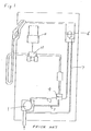
- Apparatus which attempts to solve the above problems is disclosed in Australian Patent No. 48522/72, in the name of Gilbarco Australia Limited. One embodiment of the invention disclosed in this earlier patent specification is illustrated in Figures 1 and 2 of the accompanying drawings.
- In Figures 1 and 2 a dispensing system is illustrated which includes a gas separator 1 arranged such that gas entering the system is substantially drawn off through pipe 2, while substantially gas-free fuel passes via
pipe 3 throughvalve 4 andmeter 10 for dispensing. The pipe 2 passes through aventuri 5 and into asump 6. Any fuel accumulating insump 6 is returned by pipe 7 to the inlet of a pump unit (not shown). When gas-free fuel is passing along line 2 the venturi creates a reduction in pressure, hereinafter referred to as a vacuum, inchamber 8 shown in Figure 2 which causesvalve 4 to open. However should air be present, the vacuum is reduced and thevalve 4 closes under the action of spring 9, shutting off the fuel for dispensing when gas is present, and therefore only permitting gas-free fuel to pass to themeter 10 which is monitored by acomputer 11. - It has been found that employing a system as disclosed in Figures 1 and 2 is not an ideal solution to the problem as the system tends to hunt.
- According to the present invention there is provided a fuel dispenser comprising a gas detector for producing an electrical signal in dependence upon the presence of gas in fuel flowing through the detector, and processing means for receiving the electrical signal and controlling the dispensing of fuel at least in part in dependence upon the signal received. By employing such a dispenser it is possible to control the dispensing of fuel in any manner desired in response to said received signal. This can be employed to reduce or prevent hunting and provides flexibility of control, enabling the dispenser to be easily adapted to comply with different legislative conditions.
- Preferably the dispenser further comprises a fuel separator including an inlet for receiving fuel and first and second outlets, wherein the first outlet is positioned so as to receive a greater proportion of gas than the second outlet and wherein the gas detector receives fuel from the first outlet and fuel for dispensing is received from the second outlet. This permits gas to be drawn off through the gas detector which enables fuel to be dispensed as normal if the gas drawn through the detector is below a preset level. If the gas content exceeds this preset level fuel dispensing can be stopped and the system purged by the gas passing through the detector. Also, by employing such a simple separator the concentration of air can be 20 times greater passing through the first outlet than passing through the second outlet. Fuel passing through the gas detector is advantageously recycled through the separator, preferably first flowing into a vented reservoir so that any gas can be vented off.
- Fuel leaving through the second outlet of the separator preferably passes through a meter before being dispensed, such that only substantially gas free fuel is metered.
- It is advantageous that the gas detector comprises a venturi device and that this comprises a first and second closed chamber separated by a flexible diaphragm, an inlet and outlet in the first chamber forming a venturi device such that fuel passing through them produces a reduction in pressure in the first chamber, the second chamber being connected by a passage to the outlet of the detector. This enables the second chamber to be sealed from the atmosphere.
- Advantageously a metallic member is attached to the diaphragm which is adapted to be moved by the diaphragm into and out of a magnetic field between a magnetic source and a magnetically sensitive switching element in the casing of the detector, for producing said electrical signal. This enables an output to be obtained through the casing of the gas detector without the need for an aperture in the casing.
- The fuel dispenser may additionally comprise a nozzle through which fuel is dispensed, the nozzle being attached to the main body of the dispenser by a flexible hose, wherein the dispenser includes a cradle for the nozzle to be returned to when not in use, and hose cock switch for transmitting a signal to the computer indicative of the presence or absence of the nozzle in the cradle. This enables the processing means to be adapted such that, once gas-free fuel has been detected after the nozzle has been removed from the cradle, the processing means causes a valve to open allowing fuel to be dispensed, and causes the valve to close if gas is again detected. The processing means may be set such that the valve remains closed until the nozzle has been returned to the cradle, or alternatively the processing means may be set so as to cause the valve to open again if gas-free fuel is again detected in a predetermined period after the initial closing of the valve, and if no gas-free fuel is detected in said period to cause the valve to remain closed until the nozzle has been returned to its cradle.
- It is advantageous if the processing means records the duration for which gas is detected and uses this information to determine whether the fuel so far dispensed is within predetermined metrological limits for the amount of fuel so far dispensed in a transaction, and to then control the valve accordingly. This enables the dispenser to dispense fuel continuously during a transaction even though the fuel received by the dispenser may for a short duration contain a very high content of gas, thereby preventing the dispenser from hunting. The valve may also have more than one setting, permitting the dispensing rate to be reduced enabling the separator to cope with a higher percentage of gas in the fuel. This provides an alternative to completely shutting off the dispensing of fuel, which can be confusing to an operator of the dispenser.
- Advantageously the processing means records the duration for which gas is detected and provides warning if this exceeds a predetermined limit. This warning could take the form of a signal direct to a pump attendant and/or could provide some sort of flag within the dispenser to warn a service engineer that there is a problem.
- One embodiment of the invention will now be described by way of example only with reference to Figures 3 and 4 of the accompanying drawings of which:
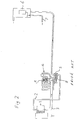
- Figure 3 schematically depicts a fuel dispenser in accordance with the present invention;
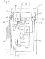
- Figure 4A is a cross-section through the gas detector of the fuel dispenser depicted in Figure 3, and
- Figure 4B is a cross-section along the line X-X of Figure 4A.
- Referring to Figure 3 the
fuel dispenser 20 comprises apump 21 for raising fuel from an underground tank viasuction pipe 22 which is then fed toseparator 23. In theseparator 23 the fuel passes through amesh 24 which encourages gases to separate out of the fuel. Substantially gas-free fuel is supplied throughpipe 25 via meter 26,valve 27 andflexible hose 28 tonozzle 29 from where it is dispensed. Thenozzle 29 is shown resting in itscradle 30 which incorporates ahose cock switch 31 which registers the presence of thenozzle 29 and transmits this information to acomputer 32. - The
computer 32 in addition to receiving information from thehose cock switch 30 also receives information from the meter 26, aremote console 33 controlled by the service station attendant, anduser control panel 34. Thecomputer 32 controls thepump 21 and thevalve 27, and also provides information to adisplay 35. In addition to this the computer also receives information from agas detector 36 which is illustrated in more detail in Figures 4A and 4B. - The
gas detector 36 receives gas and fuel via apipe 37 from the top portion of theseparator 23 where most of the gas is accumulated. As is described in more detail below with reference to Figures 4A and 4B gas/fuel passing viapipe 37 throughgas detector 36 passes through a venturi in the detector which causes a switch within the gas detector to open and close dependent on the amount of gas present. Fuel and gas passing through the detector is transmitted viapipe 38 to asump 39 where the gas is vented off to the atmosphere via abreather 40 located in thenozzle cradle 30. Thesump 39 includes afloat 41 which, when the level of fuel within thesump 39 is high enough, raisesvalve 42 such that the fuel is drained viapipe 43 back to the inlet, 22. - Referring to Figure 4A the
gas detector 36 of Figure 3 comprises an inlet 49 andoutlet 50 which are connected topipes region 51 causing pressure in afirst chamber 52 to be reduced via theapperture 53, when fuel is flowing from the inlet 49 to theoutlet 50. Thechamber 52 is sealed bydiaphragm 54 which also seals asecond chamber 55. Thissecond chamber 55 is connected viavent 56 to theoutlet 50. Connected to thediaphragm 54 is ametallic member 57 which is biased in direction "A" byspring 58. - In operation fuel passing from the inlet to the outlet causes a vacuum which acts against the
spring 58 and draws themetallic member 57 in direction "B". However when a substantial proportion of gas is present in the fuel the vacuum in thefirst chamber 52 decreases and themetallic member 57 moves in a direction "A" such that it moves into arecess 59. Therecess 59 is positioned between tworecesses gas detector 36 as can be seen more clearly from Figure 4B. Inaperture 60 there is inserted a piece ofmagnetic material 62, and inaperture 61 there is inserted a magneticallysensitive reed switch 63 connected bygland 64 tocable 65 which is connected to thecomputer 32 of Figure 3. When substantially gas-free fuel is flowing through thedetector 35 themetallic member 57 is located as shown in Figure 4, and a magnetic field generated bymagnetic member 62 causes the contacts in thereed switch 63 to be closed. When fuel flow stops, or gas is present, the vacuum inchamber 52 decreases andspring 58 urges themetallic member 57 into therecess 59 such that thereed switch 63 is shielded from the magnetic field, causingswitch 63 to open. - To operate the fuel dispenser a pump attendant at the remote console 33 (Figure 3) enables the dispenser, either after it had been shut down or after a previous transaction has been completed. An operator wishing to use the pump selects the grade of fuel he requires via
user control 34 and removesnozzle 29 fromnozzle cradle 30 and activates thehose cock switch 31, in response to which thecomputer 32 activatespump 21. When gas-free fuel passes through thegas detector 36, thereed switch 63 closes, and the computer causesvalve 27 to open permitting fuel to be dispensed vianozzle 29. Gas separated from the fuel viaseparator 23 and passing throughgas detector 36 causes thereed switch 63 to open. Thecomputer 32 records the duration for which the reed switch is open and uses this time, with information from the meter 26, to calculate whether the fuel dispensed meets metrological limits for the current transaction. If it is too close to such limits, thecomputer 32 partially shuts thevalve 27 slowing the rate of fuel being dispensed providing theseparator 23 with more time in which to separate the fuel. If this does not bring the transaction further back within the metrological limits thecomputer 32 shuts thevalve 27 completely. Meanwhile gas in the system is purged by passing through thegas detector 36 andpipe 38 to thesump 39 where it is vented, any fuel accumulating being returned to thepump inlet 21. If within a predetermined time thegas detector 36 again changes state, indicating that substantially pure fuel is passing through it, thecomputer 32 reopensvalve 27 and the transaction continues. However if gas continues to pass through thegas detector 36 for a period longer than the predetermined time thecomputer 32 stops thepump 21 and terminates the transaction until thenozzle 29 has been replaced. Thecomputer 32 also transmits a signal to thecontrol console 33 to draw the attendant's attention to the fact that the transaction had to be terminated. - In addition to the above functions, the
computer 32 also calculates the percentage of total operating time of the pump for which the gas detector indicates gas to be present. When this exceeds a predetermined percentage the service engineer is informed during the next service viadisplay 35.
Claims (16)
- A fuel dispenser comprising a gas detector (36) for producing an electrical signal in dependence upon the presence of gas in fuel flowing through the detector, and processing means (32) for receiving the electrical signal and controlling the dispensing of fuel at least in part in dependence upon the signal received.
- A fuel dispenser as claimed in claim 1 further comprising a fuel separator (23) including an inlet for receiving fuel and first and second outlets, wherein the first outlet (37) is positioned such as to receive a greater proportion of gas than the second outlet (25), and wherein the gas detector (36) receives fuel from the first outlet (37), and fuel for dispensing is received from the second outlet (25).
- A fuel dispenser as claimed in claim 2 wherein fuel passing through the gas detector is recycled through the separator.
- A fuel dispenser as claimed in claim 2 or 3 wherein fuel from the second outlet of the separator passes through a meter (26) before being dispensed.
- A fuel dispenser as claimed in any preceding claim wherein fuel after passing through the detector, flows into a vented reservoir (39).
- A fuel dispenser as claimed in any preceding claim wherein the gas detector comprises a venturi device (49, 50, 51).
- A gas detector for detecting the presence of gas in a fuel, the detector comprising a first and a second closed chamber (52, 55) separated by a flexible diaphragm (54), and an inlet (49) and outlet (50) in the first chamber (52) of such dimensions and relative displacement that fuel passing through them produces a reduction in pressure in the first chamber (52) by the Venturi effect, the second chamber (55) being connected by a passage (56) to the outlet (50).
- A fuel dispenser as claimed in claim 6 comprising a gas detector as claimed in claim 7.
- A fuel dispenser as claimed in claim 6 or 8 comprising a metallic member (57) attached to a diaphragm (54) which is adapted to be moved by the diaphragm into and out of a magnetic field between a magnetic source (67) of the detector and a magnetically sensitive switching element (63) in the casing of the detector for producing said electrical signal.
- A fuel dispenser as claimed in any one of claims 1 to 6, 8 or 9 further comprising a nozzle (29) through which fuel is dispensed, the nozzle being attached to a main body (20) of the dispenser by a flexible hose (28), wherein the dispenser includes a cradle (30) for the nozzle to be returned to when not in use, and a hose cock switch (31) for transmitting a signal to the processing means (32) indicative of the presence or absence of the nozzle (29) in the cradle (30).
- A fuel dispenser as claimed in claim 10 wherein once gas free fuel has been detected after the nozzle has been removed from the cradle the processing means causes a valve (27) to open allowing fuel to be dispensed, and to cause the valve (27) to close if gas is then detected.
- A fuel dispenser as claimed in claim 11 wherein the valve remains closed until the nozzle has been returned to the cradle.
- A fuel dispenser as claimed in claim 11 wherein the processing means causes the valve to open again if gas-free fuel is again detected in a predetermined period after the initial closing of the valve and causes the valve to remain closed until the nozzle has been returned to its cradle if gas-free fuel is not detected in said period.
- A fuel dispenser as claimed in claim 11, 12 or 13 wherein the processing means records the duration for which gas is detected and uses this information to determine whether the fuel so far dispensed is within predetermined metrological limits for the amount of fuel so far dispensed in the transaction, and controls the valve accordingly.
- A fuel dispenser as claimed in any one of claims 11 to 14 wherein the valve has more than one setting permitting flow rate to be modified.
- A fuel dispenser as claimed in any one of claims 1 to 6 or 8 to 15 wherein the processing means records the duration for which gas is detected and provides a warning if this exceeds a predetermined limit.
Applications Claiming Priority (2)
| Application Number | Priority Date | Filing Date | Title |
|---|---|---|---|
| GB9119605A GB2259497B (en) | 1991-09-13 | 1991-09-13 | A fuel dispenser |
| GB9119605 | 1991-09-13 |
Publications (3)
| Publication Number | Publication Date |
|---|---|
| EP0532202A2 true EP0532202A2 (en) | 1993-03-17 |
| EP0532202A3 EP0532202A3 (en) | 1993-07-14 |
| EP0532202B1 EP0532202B1 (en) | 1995-06-07 |
Family
ID=10701373
Family Applications (1)
| Application Number | Title | Priority Date | Filing Date |
|---|---|---|---|
| EP92307782A Expired - Lifetime EP0532202B1 (en) | 1991-09-13 | 1992-08-26 | A fuel dispenser |
Country Status (8)
| Country | Link |
|---|---|
| EP (1) | EP0532202B1 (en) |
| AT (1) | ATE123475T1 (en) |
| DE (1) | DE69202841T2 (en) |
| FI (1) | FI924073A (en) |
| GB (1) | GB2259497B (en) |
| HU (1) | HUT62239A (en) |
| NO (1) | NO923515L (en) |
| PL (1) | PL295886A1 (en) |
Cited By (5)
| Publication number | Priority date | Publication date | Assignee | Title |
|---|---|---|---|---|
| WO1997041057A1 (en) * | 1996-04-29 | 1997-11-06 | Tankanlagen Salzkotten Gmbh | Device metering and measuring quantities of liquid |
| WO1998050303A1 (en) * | 1997-05-05 | 1998-11-12 | Delaware Capital Formation, Inc. | Air separating fuel dispensing system |
| WO2006016793A1 (en) * | 2004-08-13 | 2006-02-16 | Jorge Cortes Garcia | Electromechanical system for extracting air and vapours from liquefied petroleum gas for the conveying and metering thereof |
| EP1742026A1 (en) * | 2005-07-08 | 2007-01-10 | Dresser Wayne Aktiebolag | Gas meter |
| US7814942B2 (en) | 2005-06-29 | 2010-10-19 | Dresser, Inc. | Vapor recovery system for low temperatures |
Citations (1)
| Publication number | Priority date | Publication date | Assignee | Title |
|---|---|---|---|---|
| AU4852272A (en) | 1971-11-17 | 1974-05-09 | Gilbarco Aust Limited | Air and/or vapour separation device |
Family Cites Families (9)
| Publication number | Priority date | Publication date | Assignee | Title |
|---|---|---|---|---|
| GB860622A (en) * | 1957-05-17 | 1961-02-08 | Junkers & Co | Improvements in or relating to liquid pressure actuated control devices for automatically switching on and off the heating means of liquid flow heaters |
| GB926537A (en) * | 1958-12-22 | 1963-05-22 | Hans Vaillant | Electric continuous-flow heater with water deficiency safety device |
| GB1315855A (en) * | 1970-03-14 | 1973-05-02 | Porter Lancastrian Ltd | Dispensing of carbonated beverages |
| AT313095B (en) * | 1972-05-17 | 1974-01-25 | Schwelm Strager Tankgeraetebau | Gas measurement prevention device |
| GB1360225A (en) * | 1972-10-19 | 1974-07-17 | Distillers Co Carbon Dioxide | Carbonated liquid moving apparatus |
| US4611729A (en) * | 1984-08-28 | 1986-09-16 | Dresser Industries, Inc. | Universal nozzle boot for fuel dispenser |
| FR2636056B1 (en) * | 1988-09-02 | 1991-05-24 | Schlumberger Ind Sa | DEVICE FOR AUTOMATICALLY CONTROLLING A HYDROCARBON LANCE ACCORDING TO THE GAS CONTENT OF THE HYDROCARBON |
| IT1234751B (en) * | 1989-02-10 | 1992-05-26 | Rossignoli Michele E C | HYDROPRESSOSTATIC VALVE PARTICULARLY FOR HEATING SYSTEMS EQUIPPED WITH DOMESTIC WATER PRODUCTION. |
| ATE90070T1 (en) * | 1990-09-04 | 1993-06-15 | Scheidt & Bachmann Gmbh | DEVICE FOR ADJUSTING THE SUPPLY OF LIQUID FUEL TO A METER. |
-
1991
- 1991-09-13 GB GB9119605A patent/GB2259497B/en not_active Expired - Fee Related
-
1992
- 1992-08-26 DE DE69202841T patent/DE69202841T2/en not_active Expired - Fee Related
- 1992-08-26 AT AT92307782T patent/ATE123475T1/en active
- 1992-08-26 EP EP92307782A patent/EP0532202B1/en not_active Expired - Lifetime
- 1992-09-10 PL PL29588692A patent/PL295886A1/en unknown
- 1992-09-10 NO NO92923515A patent/NO923515L/en unknown
- 1992-09-11 HU HU9202922A patent/HUT62239A/en unknown
- 1992-09-11 FI FI924073A patent/FI924073A/en not_active Application Discontinuation
Patent Citations (1)
| Publication number | Priority date | Publication date | Assignee | Title |
|---|---|---|---|---|
| AU4852272A (en) | 1971-11-17 | 1974-05-09 | Gilbarco Aust Limited | Air and/or vapour separation device |
Cited By (8)
| Publication number | Priority date | Publication date | Assignee | Title |
|---|---|---|---|---|
| WO1997041057A1 (en) * | 1996-04-29 | 1997-11-06 | Tankanlagen Salzkotten Gmbh | Device metering and measuring quantities of liquid |
| US6196065B1 (en) | 1996-04-29 | 2001-03-06 | Marconi Commerce Systems Gmbh & Co. Kg | Device metering and measuring quantities of liquid |
| WO1998050303A1 (en) * | 1997-05-05 | 1998-11-12 | Delaware Capital Formation, Inc. | Air separating fuel dispensing system |
| US5884809A (en) * | 1997-05-05 | 1999-03-23 | Delaware Capital Formation, Inc. | Air separating fuel dispensing system |
| WO2006016793A1 (en) * | 2004-08-13 | 2006-02-16 | Jorge Cortes Garcia | Electromechanical system for extracting air and vapours from liquefied petroleum gas for the conveying and metering thereof |
| US7814942B2 (en) | 2005-06-29 | 2010-10-19 | Dresser, Inc. | Vapor recovery system for low temperatures |
| EP1742026A1 (en) * | 2005-07-08 | 2007-01-10 | Dresser Wayne Aktiebolag | Gas meter |
| US7963423B2 (en) | 2005-07-08 | 2011-06-21 | Dresser, Inc. | Fuel dispensing unit with gas sensor |
Also Published As
| Publication number | Publication date |
|---|---|
| EP0532202B1 (en) | 1995-06-07 |
| PL295886A1 (en) | 1993-05-17 |
| GB9119605D0 (en) | 1991-10-23 |
| NO923515L (en) | 1993-03-15 |
| FI924073A0 (en) | 1992-09-11 |
| GB2259497A (en) | 1993-03-17 |
| HUT62239A (en) | 1993-04-28 |
| EP0532202A3 (en) | 1993-07-14 |
| DE69202841T2 (en) | 1995-10-19 |
| HU9202922D0 (en) | 1992-12-28 |
| DE69202841D1 (en) | 1995-07-13 |
| NO923515D0 (en) | 1992-09-10 |
| FI924073A (en) | 1993-03-14 |
| GB2259497B (en) | 1994-06-22 |
| ATE123475T1 (en) | 1995-06-15 |
Similar Documents
| Publication | Publication Date | Title |
|---|---|---|
| US5363988A (en) | Fuel dispenser controlled in dependence on an electrical signal from a gas detector of the dispenser | |
| US5988232A (en) | Vapor recovery system employing oxygen detection | |
| US5507325A (en) | Vapor recovery system for fuel dispensers | |
| US4167958A (en) | Hydrocarbon fuel dispensing, vapor controlling system | |
| US4310033A (en) | Liquid dispensing and uphill vapor recovery system | |
| CN109476474A (en) | Fuel storage and distributing equipment | |
| EP0532202B1 (en) | A fuel dispenser | |
| US7963423B2 (en) | Fuel dispensing unit with gas sensor | |
| US4167957A (en) | Hydrocarbon fuel dispensing, vapor controlling system | |
| US6179163B1 (en) | System and method for evaluating the presence of air in a liquid-state fuel stream | |
| US3542092A (en) | Automatic shut-off dispensing nozzle | |
| US5613535A (en) | Fuel dispenser shutoff switch | |
| US1599081A (en) | Apparatus for dispensing liquids through meters | |
| US20040016474A1 (en) | Multiproduct fuel dispenser using a common meter | |
| EP1035071B1 (en) | Fuel dispensing system with shut off device upon detection of fuel flow in vapour recovery line | |
| EP1557650A1 (en) | Electronic air separation system | |
| US6247615B1 (en) | Fluid flow system and method with low flow inhibiting | |
| US1987766A (en) | Liquid dispensing apparatus | |
| JPH0551098A (en) | Oil feeding system | |
| JPS61142195A (en) | Recovery device for vapor | |
| EP1739053B1 (en) | Fuel vapour recovery system with temperature sensor and method therefor | |
| JP3163442B2 (en) | Fuel supply system with fuel leak detection function | |
| CA2141783A1 (en) | Phase responsive fluid delivery | |
| JPH07112880B2 (en) | Refueling device with mixed oil detection function | |
| MXPA00003663A (en) | Vapor recovery system employing oxygen detection |
Legal Events
| Date | Code | Title | Description |
|---|---|---|---|
| PUAI | Public reference made under article 153(3) epc to a published international application that has entered the european phase |
Free format text: ORIGINAL CODE: 0009012 |
|
| AK | Designated contracting states |
Kind code of ref document: A2 Designated state(s): AT BE CH DE DK ES FR GB GR IE IT LI LU MC NL PT SE |
|
| PUAL | Search report despatched |
Free format text: ORIGINAL CODE: 0009013 |
|
| AK | Designated contracting states |
Kind code of ref document: A3 Designated state(s): AT BE CH DE DK ES FR GB GR IE IT LI LU MC NL PT SE |
|
| 17P | Request for examination filed |
Effective date: 19930804 |
|
| 17Q | First examination report despatched |
Effective date: 19940816 |
|
| RBV | Designated contracting states (corrected) |
Designated state(s): AT BE CH DE DK ES FR GR IE IT LI LU MC NL PT SE |
|
| GRAA | (expected) grant |
Free format text: ORIGINAL CODE: 0009210 |
|
| AK | Designated contracting states |
Kind code of ref document: B1 Designated state(s): AT BE CH DE DK ES FR GR IE IT LI LU MC NL PT SE |
|
| PG25 | Lapsed in a contracting state [announced via postgrant information from national office to epo] |
Ref country code: NL Effective date: 19950607 Ref country code: MC Free format text: LAPSE BECAUSE OF NON-PAYMENT OF DUE FEES Effective date: 19950607 Ref country code: LI Effective date: 19950607 Ref country code: IT Free format text: LAPSE BECAUSE OF FAILURE TO SUBMIT A TRANSLATION OF THE DESCRIPTION OR TO PAY THE FEE WITHIN THE PRE;WARNING: LAPSES OF ITALIAN PATENTS WITH EFFECTIVE DATE BEFORE 2007 MAY HAVE OCCURRED AT ANY TIME BEFORE 2007. THE CORRECT EFFECTIVE DATE MAY BE DIFFERENT FROM THE ONE RECORDED.SCRIBED TIME-LIMIT Effective date: 19950607 Ref country code: GR Free format text: LAPSE BECAUSE OF FAILURE TO SUBMIT A TRANSLATION OF THE DESCRIPTION OR TO PAY THE FEE WITHIN THE PRESCRIBED TIME-LIMIT Effective date: 19950607 Ref country code: ES Free format text: THE PATENT HAS BEEN ANNULLED BY A DECISION OF A NATIONAL AUTHORITY Effective date: 19950607 Ref country code: DK Effective date: 19950607 Ref country code: CH Effective date: 19950607 Ref country code: BE Effective date: 19950607 Ref country code: AT Effective date: 19950607 |
|
| REF | Corresponds to: |
Ref document number: 123475 Country of ref document: AT Date of ref document: 19950615 Kind code of ref document: T |
|
| REG | Reference to a national code |
Ref country code: IE Ref legal event code: FG4D Free format text: 64091 |
|
| REF | Corresponds to: |
Ref document number: 69202841 Country of ref document: DE Date of ref document: 19950713 |
|
| PG25 | Lapsed in a contracting state [announced via postgrant information from national office to epo] |
Ref country code: LU Free format text: LAPSE BECAUSE OF NON-PAYMENT OF DUE FEES Effective date: 19950831 Ref country code: IE Free format text: LAPSE BECAUSE OF NON-PAYMENT OF DUE FEES Effective date: 19950831 |
|
| PG25 | Lapsed in a contracting state [announced via postgrant information from national office to epo] |
Ref country code: SE Effective date: 19950907 Ref country code: PT Effective date: 19950907 |
|
| ET | Fr: translation filed | ||
| REG | Reference to a national code |
Ref country code: CH Ref legal event code: PL |
|
| NLV1 | Nl: lapsed or annulled due to failure to fulfill the requirements of art. 29p and 29m of the patents act | ||
| PLBE | No opposition filed within time limit |
Free format text: ORIGINAL CODE: 0009261 |
|
| STAA | Information on the status of an ep patent application or granted ep patent |
Free format text: STATUS: NO OPPOSITION FILED WITHIN TIME LIMIT |
|
| 26N | No opposition filed | ||
| PGFP | Annual fee paid to national office [announced via postgrant information from national office to epo] |
Ref country code: DE Payment date: 20010820 Year of fee payment: 10 |
|
| PGFP | Annual fee paid to national office [announced via postgrant information from national office to epo] |
Ref country code: FR Payment date: 20020808 Year of fee payment: 11 |
|
| PG25 | Lapsed in a contracting state [announced via postgrant information from national office to epo] |
Ref country code: DE Free format text: LAPSE BECAUSE OF NON-PAYMENT OF DUE FEES Effective date: 20030301 |
|
| PG25 | Lapsed in a contracting state [announced via postgrant information from national office to epo] |
Ref country code: FR Free format text: LAPSE BECAUSE OF NON-PAYMENT OF DUE FEES Effective date: 20040430 |
|
| REG | Reference to a national code |
Ref country code: FR Ref legal event code: ST |